ST STEVAL-IHM015V1 User manual

October 2008 Rev 2 1/53
UM0432
User manual
Low voltage motor control demonstration board
based on ST7MC MCU
Introduction
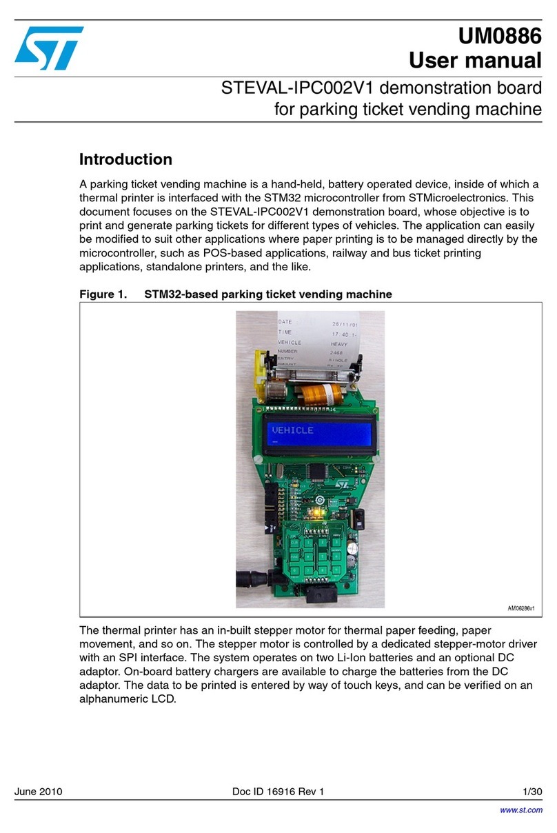
The low-voltage motor control demonstration board (also referred to by its order code
STEVAL-IHM015V1) is a complete development platform for low-voltage motor control
applications. Based on a cost-effective, flexible and open design, it allows easy
demonstration of ST7MC capabilities to drive low-voltage synchronous motors. It includes
an ST7MC 8-bit microcontroller with a 16-Kbyte internal Flash memory. The STEVAL-
IHM015V1 comes with all the hardware necessary for developing motor control applications
based on ST7MC peripherals including a motor control peripheral (MTC) and serial
communication interface (SCI). The STEVAL-IHM015V1 uses an in-circuit communication
(ICC) standard interface to connect to the host PC via in-circuit debuggers/programmers
such as the in DART-STX board from Softec. The board’s power stage is designed to
support up to 25 A and up to 48 V. With the included power MOSFET device STS8DNH3LL
in SO-8 package, the maximum input voltage is 30 V and the maximum current rating is 8 A.
The power supply stage can be easily configured to accept a wide range of input voltages.
Figure 1. STEVAL-IHM015V1
Features
■Voltage range from 5 to 48 V
■Maximum current up to 25 A
■Power MOSFET STS8DNH3LL (dual n-channel) 8 A/30 V included
■Compatible with power MOSFET in SO-8 and DPAK packages
■10 V auxiliary power supply connector
■Serial communication interface connector
■Programming and debug support via a 10-pin ICC connector
■On-board 2 K-bit (256 bytes) serial memory
■Four potentiometers for runtime settings
■Start/stop button
■Reset button
■Debug pins available
www.st.com
Downloaded from Elcodis.com electronic components distributor

Contents UM0432
2/53
Contents
1 System architecture . . . . . . . . . . . . . . . . . . . . . . . . . . . . . . . . . . . . . . . . . 7
2 Safety and operating instructions . . . . . . . . . . . . . . . . . . . . . . . . . . . . . . 8
2.1 General . . . . . . . . . . . . . . . . . . . . . . . . . . . . . . . . . . . . . . . . . . . . . . . . . . . . 8
2.2 Intended use of the demonstration board . . . . . . . . . . . . . . . . . . . . . . . . . . 8
2.3 Installing the demonstration board . . . . . . . . . . . . . . . . . . . . . . . . . . . . . . . 8
2.4 Electronic connections . . . . . . . . . . . . . . . . . . . . . . . . . . . . . . . . . . . . . . . . 8
2.5 Operating the demonstration board . . . . . . . . . . . . . . . . . . . . . . . . . . . . . . 9
3 ST7FMC2S4T6 microcontroller functions . . . . . . . . . . . . . . . . . . . . . . . 10
3.1 Main features . . . . . . . . . . . . . . . . . . . . . . . . . . . . . . . . . . . . . . . . . . . . . . 10
4 STS8DNH3LL characteristics . . . . . . . . . . . . . . . . . . . . . . . . . . . . . . . . . 12
5 Electrical characteristics of the board . . . . . . . . . . . . . . . . . . . . . . . . . 13
6 Board architecture . . . . . . . . . . . . . . . . . . . . . . . . . . . . . . . . . . . . . . . . . . 14
6.1 Power supply . . . . . . . . . . . . . . . . . . . . . . . . . . . . . . . . . . . . . . . . . . . . . . 15
6.2 Power stage . . . . . . . . . . . . . . . . . . . . . . . . . . . . . . . . . . . . . . . . . . . . . . . 15
6.3 ICC connector . . . . . . . . . . . . . . . . . . . . . . . . . . . . . . . . . . . . . . . . . . . . . 17
6.4 SDI interface (serial data interface) . . . . . . . . . . . . . . . . . . . . . . . . . . . . . 18
6.5 Board schematic . . . . . . . . . . . . . . . . . . . . . . . . . . . . . . . . . . . . . . . . . . . . 19
7 Motor control operations . . . . . . . . . . . . . . . . . . . . . . . . . . . . . . . . . . . . 21
7.1 Environmental considerations . . . . . . . . . . . . . . . . . . . . . . . . . . . . . . . . . 21
7.2 Hardware requirements . . . . . . . . . . . . . . . . . . . . . . . . . . . . . . . . . . . . . . 21
7.3 Software requirements . . . . . . . . . . . . . . . . . . . . . . . . . . . . . . . . . . . . . . . 22
7.3.1 Installing the software . . . . . . . . . . . . . . . . . . . . . . . . . . . . . . . . . . . . . . 22
7.4 Board setup . . . . . . . . . . . . . . . . . . . . . . . . . . . . . . . . . . . . . . . . . . . . . . . 23
7.4.1 Choosing the right firmware . . . . . . . . . . . . . . . . . . . . . . . . . . . . . . . . . . 23
7.4.2 Configuring the firmware using the GUI . . . . . . . . . . . . . . . . . . . . . . . . . 24
7.4.3 Motor type selection . . . . . . . . . . . . . . . . . . . . . . . . . . . . . . . . . . . . . . . . 24
7.4.4 "3-phase BLAC/DC (trapezoidal)" settings . . . . . . . . . . . . . . . . . . . . . . 25
7.4.5 "3-phase BLAC/DC (trapezoidal)" advanced settings . . . . . . . . . . . . . . 27
Downloaded from Elcodis.com electronic components distributor

UM0432 Contents
3/53
7.4.6 "3-phase PMAC motor (sinewave)" settings . . . . . . . . . . . . . . . . . . . . . 29
7.4.7 "3-phase PMAC motor (sinewave)" advanced settings . . . . . . . . . . . . . 31
7.4.8 Changing the maximum current allowed by GUI . . . . . . . . . . . . . . . . . . 32
7.4.9 Compiling the firmware . . . . . . . . . . . . . . . . . . . . . . . . . . . . . . . . . . . . . 32
7.4.10 Programming the firmware . . . . . . . . . . . . . . . . . . . . . . . . . . . . . . . . . . 33
7.4.11 Setting the option bytes . . . . . . . . . . . . . . . . . . . . . . . . . . . . . . . . . . . . . 34
7.4.12 Configuring the DC input range . . . . . . . . . . . . . . . . . . . . . . . . . . . . . . . 35
7.4.13 Jumper settings table . . . . . . . . . . . . . . . . . . . . . . . . . . . . . . . . . . . . . . . 35
7.4.14 Board connection . . . . . . . . . . . . . . . . . . . . . . . . . . . . . . . . . . . . . . . . . . 36
7.4.15 Changing the maximum allowed bus voltage level . . . . . . . . . . . . . . . . 36
7.4.16 Changing the maximum allowed current level . . . . . . . . . . . . . . . . . . . . 37
7.5 Driving the BLDC motor (trapezoidal - sensorless) . . . . . . . . . . . . . . . . . 38
7.5.1 Specific connection (sensor) . . . . . . . . . . . . . . . . . . . . . . . . . . . . . . . . . 38
7.5.2 Specific jumper settings . . . . . . . . . . . . . . . . . . . . . . . . . . . . . . . . . . . . . 38
7.5.3 LED action after power-on . . . . . . . . . . . . . . . . . . . . . . . . . . . . . . . . . . . 38
7.5.4 Setting the potentiometers . . . . . . . . . . . . . . . . . . . . . . . . . . . . . . . . . . . 39
7.5.5 Running the motor (LED action) . . . . . . . . . . . . . . . . . . . . . . . . . . . . . . 39
7.5.6 Changing the real-time parameters . . . . . . . . . . . . . . . . . . . . . . . . . . . . 39
7.5.7 Stopping the motor (LED action) . . . . . . . . . . . . . . . . . . . . . . . . . . . . . . 40
7.5.8 Configuring the system for BEMF amplification . . . . . . . . . . . . . . . . . . . 40
7.5.9 Detecting the BEMF during the PWM on time . . . . . . . . . . . . . . . . . . . . 40
7.5.10 Detecting the BEMF using the internal reference . . . . . . . . . . . . . . . . . 41
7.5.11 Detecting the BEMF using the external reference VBus/2 . . . . . . . . . . . 41
7.5.12 Detecting the BEMF using the external reference and reconstructed
neutral point of the motor . . . . . . . . . . . . . . . . . . . . . . . . . . . . . . . . . . . . 42
7.6 Driving the BLDC motor (trapezoidal - sensored) . . . . . . . . . . . . . . . . . . 42
7.6.1 Specific sensor connections . . . . . . . . . . . . . . . . . . . . . . . . . . . . . . . . . 42
7.6.2 Specific jumper settings . . . . . . . . . . . . . . . . . . . . . . . . . . . . . . . . . . . . . 42
7.6.3 LED action after power-on . . . . . . . . . . . . . . . . . . . . . . . . . . . . . . . . . . . 43
7.6.4 Setting the potentiometers . . . . . . . . . . . . . . . . . . . . . . . . . . . . . . . . . . . 43
7.6.5 Running the motor (LED action) . . . . . . . . . . . . . . . . . . . . . . . . . . . . . . 43
7.6.6 Changing the real-time parameters . . . . . . . . . . . . . . . . . . . . . . . . . . . . 43
7.6.7 Stopping the motor (LED action) . . . . . . . . . . . . . . . . . . . . . . . . . . . . . . 44
7.7 Driving the BLAC motor . . . . . . . . . . . . . . . . . . . . . . . . . . . . . . . . . . . . . . 44
7.7.1 Specific sensor connections . . . . . . . . . . . . . . . . . . . . . . . . . . . . . . . . . 44
7.7.2 Specific jumper settings . . . . . . . . . . . . . . . . . . . . . . . . . . . . . . . . . . . . . 45
7.7.3 LED action after power-on . . . . . . . . . . . . . . . . . . . . . . . . . . . . . . . . . . . 45
Downloaded from Elcodis.com electronic components distributor

Contents UM0432
4/53
7.7.4 Setting the potentiometers . . . . . . . . . . . . . . . . . . . . . . . . . . . . . . . . . . . 45
7.7.5 Running the motor (LED action) . . . . . . . . . . . . . . . . . . . . . . . . . . . . . . 45
7.7.6 Changing the real-time parameters . . . . . . . . . . . . . . . . . . . . . . . . . . . . 46
7.7.7 Stopping the motor (LED action) . . . . . . . . . . . . . . . . . . . . . . . . . . . . . . 46
8 Bill of materials . . . . . . . . . . . . . . . . . . . . . . . . . . . . . . . . . . . . . . . . . . . . 47
9 References . . . . . . . . . . . . . . . . . . . . . . . . . . . . . . . . . . . . . . . . . . . . . . . . 50
10 Known limitations . . . . . . . . . . . . . . . . . . . . . . . . . . . . . . . . . . . . . . . . . . 51
11 Revision history . . . . . . . . . . . . . . . . . . . . . . . . . . . . . . . . . . . . . . . . . . . 52
Downloaded from Elcodis.com electronic components distributor

UM0432 List of tables
5/53
List of tables
Table 1. ST7FMC2S4T6 functions . . . . . . . . . . . . . . . . . . . . . . . . . . . . . . . . . . . . . . . . . . . . . . . . . . 11
Table 2. STS8DNH3LL absolute maximum ratings . . . . . . . . . . . . . . . . . . . . . . . . . . . . . . . . . . . . . 12
Table 3. Electrical characteristics of the control board . . . . . . . . . . . . . . . . . . . . . . . . . . . . . . . . . . . 13
Table 4. Power supply jumper settings . . . . . . . . . . . . . . . . . . . . . . . . . . . . . . . . . . . . . . . . . . . . . . . 15
Table 5. Compatible devices . . . . . . . . . . . . . . . . . . . . . . . . . . . . . . . . . . . . . . . . . . . . . . . . . . . . . . 16
Table 6. Firmware libraries arranged according to driving strategy . . . . . . . . . . . . . . . . . . . . . . . . . 23
Table 7. ".h" configuration files . . . . . . . . . . . . . . . . . . . . . . . . . . . . . . . . . . . . . . . . . . . . . . . . . . . . . 24
Table 8. "3-phase BLAC/DC (trapezoidal)" basic parameters . . . . . . . . . . . . . . . . . . . . . . . . . . . . . 26
Table 9. "3-phase BLAC/DC (trapezoidal)" advanced parameters . . . . . . . . . . . . . . . . . . . . . . . . . . 28
Table 10. "3-phase PMAC motor (sinewave)" basic parameters . . . . . . . . . . . . . . . . . . . . . . . . . . . . 30
Table 11. "3-phase PMAC motor (sinewave)" advanced parameters. . . . . . . . . . . . . . . . . . . . . . . . . 31
Table 12. Jumper settings table . . . . . . . . . . . . . . . . . . . . . . . . . . . . . . . . . . . . . . . . . . . . . . . . . . . . . 35
Table 13. Bus voltage threshold parameter . . . . . . . . . . . . . . . . . . . . . . . . . . . . . . . . . . . . . . . . . . . . 37
Table 14. BLDC SL jumpers setting . . . . . . . . . . . . . . . . . . . . . . . . . . . . . . . . . . . . . . . . . . . . . . . . . . 38
Table 15. Potentiometer functionality based on open/closed loop driving strategy . . . . . . . . . . . . . . 39
Table 16. BLDC SL with BEMF amplification jumper settings . . . . . . . . . . . . . . . . . . . . . . . . . . . . . . 40
Table 17. "BLDC sensored" motor connections . . . . . . . . . . . . . . . . . . . . . . . . . . . . . . . . . . . . . . . . . 42
Table 18. BLDC SR jumper settings. . . . . . . . . . . . . . . . . . . . . . . . . . . . . . . . . . . . . . . . . . . . . . . . . . 43
Table 19. Potentiometer functionality based on open/closed loop driving strategy . . . . . . . . . . . . . . 44
Table 20. "PMAC sensored" motor connections. . . . . . . . . . . . . . . . . . . . . . . . . . . . . . . . . . . . . . . . . 45
Table 21. PMAC SR jumper settings . . . . . . . . . . . . . . . . . . . . . . . . . . . . . . . . . . . . . . . . . . . . . . . . . 45
Table 22. Potentiometer functionality based on an open-/closed-loop driving strategy . . . . . . . . . . . 46
Table 23. Bill of materials . . . . . . . . . . . . . . . . . . . . . . . . . . . . . . . . . . . . . . . . . . . . . . . . . . . . . . . . . . 47
Table 24. Document revision history . . . . . . . . . . . . . . . . . . . . . . . . . . . . . . . . . . . . . . . . . . . . . . . . . 52
Downloaded from Elcodis.com electronic components distributor

List of figures UM0432
6/53
List of figures
Figure 1. STEVAL-IHM015V1 . . . . . . . . . . . . . . . . . . . . . . . . . . . . . . . . . . . . . . . . . . . . . . . . . . . . . . . 1
Figure 2. Motor control system architecture. . . . . . . . . . . . . . . . . . . . . . . . . . . . . . . . . . . . . . . . . . . . . 7
Figure 3. STS8DNH3LL . . . . . . . . . . . . . . . . . . . . . . . . . . . . . . . . . . . . . . . . . . . . . . . . . . . . . . . . . . . 12
Figure 4. Board architecture . . . . . . . . . . . . . . . . . . . . . . . . . . . . . . . . . . . . . . . . . . . . . . . . . . . . . . . 14
Figure 5. Power supply architecture . . . . . . . . . . . . . . . . . . . . . . . . . . . . . . . . . . . . . . . . . . . . . . . . . 15
Figure 6. Footprint selection of power devices . . . . . . . . . . . . . . . . . . . . . . . . . . . . . . . . . . . . . . . . . 16
Figure 7. Board layout . . . . . . . . . . . . . . . . . . . . . . . . . . . . . . . . . . . . . . . . . . . . . . . . . . . . . . . . . . . . 17
Figure 8. ICC connector. . . . . . . . . . . . . . . . . . . . . . . . . . . . . . . . . . . . . . . . . . . . . . . . . . . . . . . . . . . 17
Figure 9. SDI connector . . . . . . . . . . . . . . . . . . . . . . . . . . . . . . . . . . . . . . . . . . . . . . . . . . . . . . . . . . . 18
Figure 10. Board schematic: control block. . . . . . . . . . . . . . . . . . . . . . . . . . . . . . . . . . . . . . . . . . . . . . 19
Figure 11. Board schematic: power block . . . . . . . . . . . . . . . . . . . . . . . . . . . . . . . . . . . . . . . . . . . . . . 20
Figure 12. STVD7 for InDART-STX toolset configuration . . . . . . . . . . . . . . . . . . . . . . . . . . . . . . . . . . 23
Figure 13. Motor Type Choice window . . . . . . . . . . . . . . . . . . . . . . . . . . . . . . . . . . . . . . . . . . . . . . . . 25
Figure 14. "3-phase BLAC/DC (trapezoidal)" basic parameters window . . . . . . . . . . . . . . . . . . . . . . . 25
Figure 15. "3-phase BLAC/DC (trapezoidal)" advanced parameters window . . . . . . . . . . . . . . . . . . . 28
Figure 16. "3-phase PMAC motor (sinewave)" basic parameters window. . . . . . . . . . . . . . . . . . . . . . 29
Figure 17. "3-phase PMAC motor (sinewave)" advanced parameters window . . . . . . . . . . . . . . . . . . 31
Figure 18. ST7VD active project configuration . . . . . . . . . . . . . . . . . . . . . . . . . . . . . . . . . . . . . . . . . . 33
Figure 19. System setup for programming phase . . . . . . . . . . . . . . . . . . . . . . . . . . . . . . . . . . . . . . . . 33
Figure 20. Option byte settings . . . . . . . . . . . . . . . . . . . . . . . . . . . . . . . . . . . . . . . . . . . . . . . . . . . . . . 34
Figure 21. Programming option Auto window . . . . . . . . . . . . . . . . . . . . . . . . . . . . . . . . . . . . . . . . . . . 35
Figure 22. System setup for running phase . . . . . . . . . . . . . . . . . . . . . . . . . . . . . . . . . . . . . . . . . . . . . 36
Downloaded from Elcodis.com electronic components distributor

UM0432 System architecture
7/53
1 System architecture
A generic motor control system can be basically schematized as the arrangement of four
main blocks (see Figure 2).
●A control block, whose main tasks are to accept user commands and motor drive
configuration parameters and to provide digital signals to implement the correct motor
driving strategy.
●A power block that makes a power conversion from the DC bus transferring it into the
motor by means of a 3-phase inverter topology.
●The motor itself. The STEVAL-IHM015V1 board can drive the following kinds of motors.
– PMDC (or BLAC/BLDC) permanent magnet motors, 6-step current, both in
sensored and sensorless mode.
– PMAC (or BLAC) permanent magnet motors, sinusoidal current, only in sensored
mode.
●A power supply block that accepts a wide range of input voltages and provides the
appropriate levels to supply both the control block and power block devices.
Figure 2. Motor control system architecture
The system proposed by the STEVAL-IHM015V1 includes all the above hardware blocks
(apart from the motor) plus a software GUI to configure the motor drive. Additionally, open-
source C code is available, derived from the ST7MC motor control libraries, allowing easy
customization and extension of the control algorithms.
The control block’s core consists of an ST7MC MCU that provides the driving signals to the
power block according to a driving strategy that is closely related to the motor type and
characteristics.
The driving signals consist of three complementary PWM signals (in the range of 0-5 V) for
providing logic inputs for the high-/low-side gate drivers that belong to the power block. The
proposed system has three legs (3-phase inverter).
The power block, based on the gate drivers L6387 and power MOSFET (STS8DNH3LL),
converts the control signals from the ST7MC MCU to power signals for the 3-phase inverter
in order to drive the motor.
The board can be supplied by a DC power supply from 5 up to 48 V with a maximum current
rating up to 25 A. Refer to Section 6 for more information on the system’s architecture.
With the included power MOSFET device STS8DNH3LL, the maximum voltage rating is
30 V and the maximum current rating is 8 A.
Downloaded from Elcodis.com electronic components distributor

Safety and operating instructions UM0432
8/53
2 Safety and operating instructions
2.1 General
Warning: During assembly and operation, the STEVAL-IHM015V1
demonstration board poses several inherent hazards,
including bare wires, moving or rotating parts and hot
surfaces. Serious personal injury and damage to property
may occur if the kit or its components are used or installed
incorrectly.
All operations involving transportation, installation and use, as well as maintenance, should
be carried out by skilled technical personnel (national accident prevention rules must be
observed). Skilled technical personnel refers to suitably-qualified persons who are familiar
with the installation, use and maintenance of electronic power systems.
2.2 Intended use of the demonstration board
The STEVAL-IHM015V1 demonstration board is a component designed for demonstration
purposes only, and must not be used for electrical installations or machinery. Technical data
and information concerning the power supply conditions are detailed in the documentation
and should be strictly observed.
2.3 Installing the demonstration board
The installation and cooling of the demonstration kit boards must be in accordance with the
specifications and targeted application (see Section 7).
●The motor drive converters must be protected against excessive strain. In particular,
components should not be bent or isolating distances altered during transportation or
handling.
●No contact must be made with other electronic components and contacts.
●The boards contain electrostatically-sensitive components that are prone to damage if
used incorrectly. Do not mechanically damage or destroy the electrical components
(potential health risks).
2.4 Electronic connections
Applicable national accident prevention rules must be followed when working on the main
power supply with a motor drive. The electrical installation must be completed in accordance
with the appropriate requirements (for example, cross-sectional areas of conductors, fusing,
PE connections, etc). For further information, see Section 7.
Downloaded from Elcodis.com electronic components distributor

UM0432 Safety and operating instructions
9/53
2.5 Operating the demonstration board
A system architecture that supplies power to the STEVAL-IHM015V1 demonstration board
must be equipped with additional control and protective devices in accordance with the
applicable safety requirements (for example, compliance with technical equipment and
accident prevention rules).
Warning: Do not touch the board immediately after it has been
disconnected from the voltage supply as several parts and
power terminals containing possibly-energized capacitors
need time to discharge.
Downloaded from Elcodis.com electronic components distributor

ST7FMC2S4T6 microcontroller functions UM0432
10/53
3 ST7FMC2S4T6 microcontroller functions
3.1 Main features
●TQFP44 package.
●16 Kbyte dual-voltage Flash program memory with read-out protection capability.
●768 bytes of RAM (256 stacked bytes).
●Clock, reset and supply management with:
– enhanced reset system,
– enhanced low-voltage supervisor (LVD) for the main supply and auxiliary voltage
detector (AVD) with interrupt capability,
– clock sources: crystal/ceramic resonator oscillators and bypass for the external
clock, clock security system,
– four power-saving modes: halt, active-halt, wait and slow.
●Configurable window watchdog timer.
●Nested interrupt controller with 14 interrupt vectors.
●Two 16-bit timers.
●One 8-bit auto-reload timer.
●Serial peripheral interface (SPI).
●Serial communication interface (LINSCI™).
●Motor controller (MTC) peripheral with:
– 6 high-sink pulse-width modulator (PWM) output channels,
– asynchronous emergency stop,
– analog inputs for rotor position detection,
– permanent magnet motor coprocessor including multiplier, programmable filters,
blanking windows and event counters,
– op-amp and comparator for current limitations.
●10-bit analog-to-digital converter (ADC) with 11 inputs.
●In-circuit communication interface (ICC, debug).
Downloaded from Elcodis.com electronic components distributor

UM0432 ST7FMC2S4T6 microcontroller functions
11/53
Table 1. ST7FMC2S4T6 functions
Function I/o name Description (depends on embedded software)
MTC
MCO0 PWM outputs high-side phase A
MCO1 PWM outputs low-side phase A
MCO2 PWM outputs high-side phase B
MCO3 PWM outputs low-side phase B
MCO4 PWM outputs high-side phase C
MCO5 PWM outputs low-side phase C
MCIA, MCIB, MCIC Analog or digital input for position sensor or B.E.M.F. detection
MCVREF B.E.M.F. detection comparator reference
NMCES Emergency stop
OAP Operational amplifier positive input
OAN Operational amplifier negative input
OAZ Operational amplifier output
MCCREF Current limitation reference
MCPWMV PWM Output V user for current reference
MCZEM Debug pin C/Z event
MCDEM Debug pin C/D event
SPI
MISO Master in/slave out data
MOSI Master out/slave in data
SCK Serial clock
LINSCI™ RDI Received data input
TDO Transmit data output
10-bit ADC
AIN0 Temperature sensor input
AIN1 Bus voltage sensing input
AIN13 Trimmer P1 reading input
AIN11 Trimmer P2 reading input
AIN7 Trimmer P3 reading input
ICC
ICCCLK Output serial clock
ICCDATA Input/output serial data
ICCSEL/Vpp Programming voltage input
Other I/O
PE0 GPIO_A for GE method of BEMF detection
PE1 GPIO_B for GE method of BEMF detection
PE2 GPIO_C for GE method of BEMF detection
PE3 Start/stop push-button switch
PB7 LED management
Downloaded from Elcodis.com electronic components distributor

STS8DNH3LL characteristics UM0432
12/53
4 STS8DNH3LL characteristics
The STS8DNH3LL is a dual N-channel power MOSFET in SO-8 package (30 V, 0.018 Ω,
8 A), featuring a low gate charge and STripFET™ III.
Figure 3. STS8DNH3LL
●VDSS = 30 V
●RDS(on) = 0.018 Ω
●ID= 8 A
Note: Stresses above the limits shown in Ta b l e 2 may cause permanent damage to the device.
Table 2. STS8DNH3LL absolute maximum ratings
Symbol Parameter Value Unit
VDS Drain source voltage (VGS = 0) 30 V
VDGR Drain gate voltage (RGS = 20 kΩ)30V
VGS Gate source voltage ± 16 V
IDDrain current (continuous) at TC= 25 °C 8 A
IDDrain current (continuous) at TC= 100 °C 5 A
IDM(1)
1. Pulse width limited by safe operating area.
Drain current (pulsed) 32 A
Ptot Total dissipation at TC= 25 °C 2 W
Downloaded from Elcodis.com electronic components distributor

UM0432 Electrical characteristics of the board
13/53
5 Electrical characteristics of the board
Stresses above the limits shown in Ta b l e 3 may cause permanent damage to the devices
present inside the board. These are stress ratings only and functional operation of the
device under these conditions is not implied. Exposure to maximum rating conditions for
extended periods may affect device reliability.
A 10-volt bias current measurement may be useful to check the working status of the board.
If the measured value is considerably greater than the typical value, some damage has
occurred to the board. See the power supply configuration for a 10-V auxiliary supply.
Table 3. Electrical characteristics of the control board
Control board parameters
STEVAL-IHM015V1 Unit
Min Max
10 V auxiliary supply range – J6 5 15 V
10 V bias current (typical) 30 70 mA
VBUS – J5 (low voltage configuration)(1)
1. See Section 6.1: Power supply on page 15.
56.5V
VBUS – J5 (medium voltage configuration)(1) 6.5 9 V
VBUS – J5 (high voltage configuration)(1) 948V
Downloaded from Elcodis.com electronic components distributor

Board architecture UM0432
14/53
6 Board architecture
The STEVAL-IHM015V1 can be schematized as shown in Figure 4.
Figure 4. Board architecture
The control board’s core is the ST7MC microcontroller with a dedicated peripheral included
to drive the 3-phase brushless motor.
The user interface is made up of four potentiometers (P1, P2, P3, P4) used to set
parameters related to the specific drive (see Section 7).
Two push-button switches are also implemented.
●A Reset button for hardware resets.
●A Start/Stop button used to start and stop the motor drive (seeSection 7).
Two LEDs (green/red), each related to a specific drive, are used to obtain a status on the
system (see Section 7).
In normal functioning mode, the board is supplied by the VBUS connector J5 but an auxiliary
supply connector (J6) is included on the board to feed the drivers and the microcontroller.
The board is supplied with a 2-Kbit EEPROM (M95020) connected to the micro by the SPI
bus. To enable the on-board EEPROM memory, the J2 jumper must be closed and the
debug feature must be disabled inside the firmware. J4 can be set by connecting a jumper
between pins 1-2 or 2-3. This setting is related to a specific drive (see Section 7).
Two communication systems can be established with the microcontroller.
●ICC: used for programming/debugging purposes.
●SCI: used for data exchanges through the SDI connector.
ST7MC
Power
Supply
PWMs
Communication I/O
5V
User Interface
5V..48V
M
L6387
L6387
L6387
Vdriver
H
RSENSE
Downloaded from Elcodis.com electronic components distributor

UM0432 Board architecture
15/53
6.1 Power supply
The power supply has been designed to address a wide range of DC bus voltages from 5 to
48 V. Three power supply configurations have been implemented.
●Low voltage: 5–6.5 volts based on the L5970 boost converter.
●Medium voltage: a 6.5–9-volt direct connection to the bus.
●High voltage: 9–48 volts based on an L4976 buck converter (for VBUS > 28 V, the power
MOSFET must be replaced with the STD20NF06LT4 or STS7NF60L).
Figure 5. Power supply architecture
To supply the 5 volts to the micro, you can use either the Vref signal of the L4976D regulator
if it is used (high voltage setting in Ta bl e 4 ), or the LK112SM50TR. The first setting can be
configured by putting J8 between pins 2-3 and the second configuration by putting J8
between pins 1-2.
With the L4976D’s Vref signal, it is possible to provide the microcontroller with up to 20 mA.
With the LK112SM50TR it is possible to provide up to 200 mA.
6.2 Power stage
The power stage is based on six power MOSFETs in full 3-phase bridge configuration. The
board has three STS8DNH3LLs in SO-8 package, each containing two devices. The
maximum driving current is 8 A and the suggested maximum driving voltage is 24 V.
Different power MOSFET devices can be used, replacing U15, U17 and U18 with other
devices. Compatible devices are power MOSFETs in SO-8 package containing single or
Table 4. Power supply jumper settings
Configuration VBUS range V Driver Jumper configuration
Low voltage 5–6.5 V 7 V J23 between 1-2
J24 between 2-3
Medium voltage 6.5–9 V VBUS
J23 pin2 – J22
J24 pin 2 – J27
High voltage 9–48 V 8 V J23 between 2-3
J24 between 1-2
V (Driver) V (Micro)
L4976D
J23
2
1
1
3
L5970D
J24
2
3
1
1
LK112SM50
VBus
J22 J27
Downloaded from Elcodis.com electronic components distributor

Board architecture UM0432
16/53
dual devices and power MOSFETs in DPAK package. The board is designed to work up to
25 A and 48 V.
Figure 6. Footprint selection of power devices
Figure 6 shows one of the three legs of the bridge where it is possible to mount one of the
three kinds of devices. Tabl e 5 shows a list of compatible devices.
Table 5. Compatible devices
Place holder Packages Type Compatible devices
U15, U17, U18 SO-8 Dual STS8DNH3LL(1)
1. The above are examples of compatible devices only. See the power MOSFET selection guide for a
complete list of devices.
Q9, Q10, Q13, Q14, Q17, Q18 SO-8 Single STS20NHS3LL(1)
STS7NF60L(1)
Q11, Q12, Q15, Q16, Q19, Q20 DPAK Single STD20NF06LT4(1)
Downloaded from Elcodis.com electronic components distributor

UM0432 Board architecture
17/53
Figure 7. Board layout
6.3 ICC connector
The ICC connector (J1) is used to establish ICC communication for programming/debugging
purposes. Its pinout is shown in Figure 8. This connector is compatible with Softec’s
inDART-STX board (not included in the package).
Figure 8. ICC connector
Downloaded from Elcodis.com electronic components distributor

Board architecture UM0432
18/53
6.4 SDI interface (serial data interface)
The board is provided with an SDI interface (JP1) to establish SCI communication with
external devices. We suggest using an isolation board between the SDI interface and the
external devices. The pinout is shown in Figure 9.
Figure 9. SDI connector
Downloaded from Elcodis.com electronic components distributor

UM0432 Board architecture
19/53
6.5 Board schematic
Figure 10. Board schematic: control block
Hin PA
Lin PA
Hin PBLin PB
Hin PC
Lin PC
VaRef
VaRef
P3
P2
P1
LedCtr
Button
CHIP-SELECT
RDI
TDO
MCIA
MCIB
MCIC
GPIO_A
GPIO_B
GPIO_C
Current Sense
LedCtr
P3
P2
P1
Button
MCES
MCCFI
MCCFI
OAP
OAP
MCCREF
MCCREF
CHIP-SELECT
MCVREF
VBUSVal
TEMP
TEMP
TDO
RDI
+5
+5
+5
+5
+5
+5 +5
+5
+5
+5
+5
+5
+5
+5
Variable Adjustable
Debug Pin
Serial Communication
R7
47K
R7
47K
R9
(NC)
R9
(NC)
R20
100K
R20
100K
R14
100R
R14
100R
R10
(NC)
R10
(NC)
C12
1nF
C12
1nF
R11
(NC)
R11
(NC)
S
1
Q
2
W
3
VCC 8
VSS
4
HOLD 7
CK 6
DATA 5
U3
M95040-MN6
U3
M95040-MN6
C5
10nF
C5
10nF
C11
100nF
C11
100nF
NTC1
10K
NTC1
10K
R3
10K (NC)
R3
10K (NC)
1
2
3
4
SW3
Reset Button
SW3
Reset Button
X1
CSTCS-16MX
X1
CSTCS-16MX
1 2
J3J3
J4J4
C7
100nF
25V
C7
100nF
25V
D1
GREEN LED
D1
GREEN LED
R6
10K (NC)
R6
10K (NC)
R2
100K (NC)
R2
100K (NC)
2
3
6
74
8
1
5
-
+
U1
TS271ACD (NC)
-
+
U1
TS271ACD (NC)
P350k P350k
1 2
J2J2
1
2
3
4
JP1
HEADER 4
JP1
HEADER 4
D2
RED LED
D2
RED LED
R21
33K
R21
33K
C13
100nF
C13
100nF
C2
100nF (NC)
C2
100nF (NC)
1
2
3
4
SW4
Start/Stop
SW4
Start/Stop
R19
10K
R19
10K
R15
1M
R15
1M
C10
100nF
25V
C10
100nF
25V
P4100K P4100K
P150k P150k
2
4
6
8
10
1
3
5
7
9
J1
ICC connector : HE10 male type
J1
ICC connector : HE10 male type
R13
10K
R13
10K
R5
10K (NC)
R5
10K (NC)
C4
10nF
C4
10nF
C8
10nF
C8
10nF
R1
470
R1
470
R8
47K
R8
47K
C1
1nF (NC)
C1
1nF (NC)
R4
680
R4
680
MCO3 (HS)
1
OSC1
5
OSC2
6
Vss_1
7
Vdd_1
8
PA3/PWM0/AIN0
9
PA5/ARTIC1/AIN1
10
PB0/MCVREF
11
PB1/MCIA
12
PB2/MCIB
13
PB3/MCIC
14
PB4/MISO
15
PB5/MOSI/AIN3
16
MCO5 (HS)
3MCO4 (HS)
2
MCES
4
PB6 (HS)/SCK
17
PB7 (HS)/SS/AIN4
18
PC2/OAP
19
PC3/OAN
20
OAZ/MCCFI1/AIN6
21
PC4/MCCREF
22 PC7/MCPWMW/AIN7 23
VAREF 24
VSSA 25
VSS_0 26
VDD_0 27
RESET 28
PD0/OCMP2_A/AIN11 29
PD2/ICAP2_A/MCZEM/AIN12 31
PD1 (HS)/OCMP1_A/MCPWMV/MCDEM 30
PD3/ICAP1_A/AIN13 32
PD4/EXTCLK_A/AIN14/ICCCLK 33
PD5/AIN15/ICCDATA 34
PD6 (HS)/RDI 35
PD7 (HS)/TDO 36
PEO (HS)/OCMP2_B 37
PE1/OCMP1_B 38
PE2/ICAP2_B 39
PE3/ICAP1_B 40
VPP 41
MCO0 (HS) 42
MCO1 (HS) 43
MCO2 (HS) 44
U2
ST7FMC2S4T6-TQFP44
U2
ST7FMC2S4T6-TQFP44
R18
47K
R18
47K
C9
100nF
C9
100nF
C6
10nF
C6
10nF
C3
1uF
C3
1uF
R16
120R
R16
120R
P250k P250k
R17
47K
R17
47K
R12
10K
R12
10K
Downloaded from Elcodis.com electronic components distributor

Board architecture UM0432
20/53
Figure 11. Board schematic: power block
N772044
N773167
N773412
N772064
VBus
Va
Va
VBus
Vb
N773187
VBus
Vc
N773432
Vb
Vc
VBus VBus
Va
Va
Current Sense Current Sense
N772064N772064
N772044 N772044 N773167
N773187
VBus
Vb
Vb
Current Sense Current Sense
Vb
Vb
VBus
N773167
N773187
N773412
N773432
N773412
N773432
VcVc
Vc Vc
VBusVBus
Current Sense Current Sense
Va Va
Current Sense
Current Sense
Current Sense
Vbus
VBus
VBus
VBus
Hin PA
Lin PA
Hin PB
Lin PB
Hin PC
Lin PC
Current Sense
VBus
MCIA
MCIC
MCIB
GPIO_A
GPIO_B
GPIO_C
Current Sense
MCES
MCVREF
VBUSVal
+10
+5
VCCRefVCCRef
+10
+10
+10
+5
Va
+5
Vb
+5
Vc
Va
Vb
Vc
Vref 1
Vref 2
Va Vb Vc
+10
+5
+5 +5 +5
+5
+10
+10
+10
GND
VBus
+10VDC
GND
SO-8 (Double devices)
(Power) SO-8 (Single Devices)
DPAK (Single Devices)
Phase A
Phase B
Phase C
+5V
Hall1
GND
Hall2
Hall3
HALL SENSOR
Current Protection
SO-8 (Double devices)
(Power) SO-8 (Single Devices)
DPAK (Single Devices)
SO-8 (Double devices)
(Power) SO-8 (Single Devices)
DPAK (Single Devices)
R58 22R
R58 22R
R50
470
R50
470
C39
10uF 16V
C39
10uF 16V
D4
GREEN LED
D4
GREEN LED
C30
22nF
C30
22nF
R74
4.7K
R74
4.7K
R38
22K
R38
22K
10
9
8
411
-
+
U19C
TS274
-
+
U19C
TS274
R59
22K
R59
22K
D3
1.5KE16A
D3
1.5KE16A
D71N4148D71N4148
1
2
3
J10
PHASE OUT
J10
PHASE OUT
R81
4.7K
R81
4.7K
R48
22R
R48
22R
1
J22
CON1
J22
CON1
R27
15K
R27
15K
RF2
330K
RF2
330K
OUT 1
SYNC 2
INH 3
COMP 4
FB
5VREF
6GND
7VCC
8
U16
L5970D
U16
L5970D
R62
22K
R62
22K
R33 22R
R33 22R
C40
22nF
C40
22nF
+
C32
1uF 25V
+
C32
1uF 25V
1
2
3
J11J11
R53
15K
R53
15K
R52
0.07R
R52
0.07R
C27
100p
C27
100p
1
2
3
J12J12
R71
470
R71
470
R39
470
R39
470
1
2
3
J18J18
R61
220R
R61
220R
1
2
3
J16J16
R83
13K
R83
13K
D5
STPS1L60A
D5
STPS1L60A
C34
10nF
C34
10nF
C29
3.3nF
C29
3.3nF
R64
10K
R64
10K
C21
100nF
C21
100nF
C45
1uF 50V
C45
1uF 50V
RF1
330K
RF1
330K
R36
4.7K
R36
4.7K
N.C.
1
GND
2
VRef
3
OSC
4
Out
5
Out
6
N.C.
7
N.C.
8N.C. 9
N.C. 10
Vcc 11
Boot 12
Comp 13
FB 14
N.C. 15
N.C. 16
U10
L4976D
U10
L4976D
1
2
J6 +10VJ6 +10V
R63
470
R63
470
+
C23
100uF 25V
+
C23
100uF 25V
R41
15K
R41
15K
D8 1N4148
D8 1N4148
Lin
1
Hin
2
Vcc 3
Hvg 7
Out 6
VBoot 8
Lvg 5
GND
4
U14
L6387
U14
L6387
R56
22K
R56
22K
R35
4.7K
R35
4.7K
RF3
330K
RF3
330K
R30
3.3K
R30
3.3K
R40
220R
R40
220R
R45 200RR45 200R
R54
22K
R54
22K
+
C24
220µF ESR 42mOhm
+
C24
220µF ESR 42mOhm
R65
15K
R65
15K
Lin
1
Hin
2
Vcc 3
Hvg 7
Out 6
VBoot 8
Lvg 5
GND
4
U11
L6387
U11
L6387
D15
STPS2L25U
D15
STPS2L25U
1
2
3
J13J13
1
2
3
J21J21
+
C25
100uF 150mOhm
+
C25
100uF 150mOhm
R60
22R
R60
22R
R28
4.6K
R28
4.6K
5
6
7
411
-
+
U19B
TS274
-
+
U19B
TS274
R68
10K
R68
10K
R44
22K
R44
22K
C26
220nF
C26
220nF
12
13
14
411
-
+
U19D
TS274
-
+
U19D
TS274
1
2
J28
HEADER 2/SM
J28
HEADER 2/SM
2
1
J5 VBusJ5 VBus
D14
STPS2L25U
D14
STPS2L25U
C22
1uF 10V
C22
1uF 10V
R42
22K
R42
22K
D9 1N4148
D9 1N4148
+
C33
1uF 25V
+
C33
1uF 25V
1
2
3
J8J8
R34
4.7K
R34
4.7K
R76
22K
R76
22K
C44
1uF 50V
C44
1uF 50V
R37
22R
R37
22R
+
C42
100uF 16V
+
C42
100uF 16V
R46 22R
R46 22R
1
2
34
6
5
7 8
U18
STS8dnh3ll
U18
STS8dnh3ll
R55
2.2K
R55
2.2K
C31
100nF 25V
C31
100nF 25V
R66
22K
R66
22K
+
C28
1uF 25V
+
C28
1uF 25V
L1
470uH 0.35A
L1
470uH 0.35A
Q9
MOSFET N_0
Q9
MOSFET N_0
Q10
MOSFET N_0
Q10
MOSFET N_0
Q11
MOSFET N_0
Q11
MOSFET N_0
Q12
MOSFET N_0
Q12
MOSFET N_0
Q13
MOSFET N_0
Q13
MOSFET N_0
Q14
MOSFET N_0
Q14
MOSFET N_0
Q15
MOSFET N_0
Q15
MOSFET N_0
L3
15uH 1A
L3
15uH 1A
Q16
MOSFET N_0
Q16
MOSFET N_0
Q17
MOSFET N_0
Q17
MOSFET N_0
Q18
MOSFET N_0
Q18
MOSFET N_0
Q19
MOSFET N_0
Q19
MOSFET N_0
Q20
MOSFET N_0
Q20
MOSFET N_0
1
J27
CON1
J27
CON1
D10 1N4148D10 1N4148
R73
10K
R73
10K
C41
220p
C41
220p
1
2
3
J24
CON3
J24
CON3
R57 200R
R57 200R
R47
22K
R47
22K
1
2
3
J15J15 1
2
34
6
5
7 8
U17
STS8dnh3ll
U17
STS8dnh3ll
1
2
3
J23
CON3
J23
CON3
R67
47K
R67
47K
R43
2.2K
R43
2.2K
R72
10K
R72
10K
R75
10K
R75
10K
Q8
STN4NF03L
Q8
STN4NF03L
D6 1N4148
D6 1N4148
R51
220R
R51
220R
1
2
3
J20J20
R49
22K
R49
22K
R82
2.7K
R82
2.7K
R70
2.2K
R70
2.2K
R26
470R
R26
470R
R31200R R31200R
R29
18K
R29
18K
Lin
1
Hin
2
Vcc 3
Hvg 7
Out 6
VBoot 8
Lvg 5
GND
4
U13
L6387
U13
L6387
1
2
3
J19J19
R77
1.2K
R77
1.2K
1
2
34
6
5
7 8
U15
STS8dnh3ll
U15
STS8dnh3ll
D11 1N4148D11 1N4148
In
5
2
GND
Out 4
1
SHDN
3
By pass
U9
LK112Sxx50
U9
LK112Sxx50
1
2
3
4
5
J14J14
1
2
3
J17J17
R69
22K
R69
22K
C43
1uF 50V
C43
1uF 50V
3
2
1
411
-
+
U19A
TS274
-
+
U19A
TS274
R32
22K
R32
22K
Downloaded from Elcodis.com electronic components distributor
Table of contents
Other ST Motherboard manuals

ST
ST X-NUCLEO-IDB05A1 User manual

ST
ST STM3210B-EVAL User manual

ST
ST M24LR-DISCOVERY User manual

ST
ST STEVAL-LVLP01 User manual

ST
ST STEVAL-BLUEMIC-1 User manual

ST
ST UM0804 User manual

ST
ST STM32L152-EVAL User manual

ST
ST SPC5-UDESTK User manual

ST
ST STM32L4R9I-EVAL User manual

ST
ST SPC572LADPT80S User manual
Popular Motherboard manuals by other brands

Analog Devices
Analog Devices EVAL-SSM4567Z user guide

Texas Instruments
Texas Instruments DRV8300-EVM Series user guide

OLIMEX
OLIMEX OLIMEXINO-328 user manual

Analog Devices
Analog Devices EVAL-AD51150SDZ user guide

SOLTEK
SOLTEK SL-67D manual

Silicon Laboratories
Silicon Laboratories Sensor-EXP-EVB user guide