Pin Signal Description
6 VBUS
Auxiliary supply rail. Used to supply the STWLC68JRH chip via VOUT when
the receiver module is not placed on a transmitter. The D4 diode (see
Figure 6) avoids backflow toward the USB supply rail when VOUT is higher
than 5V.
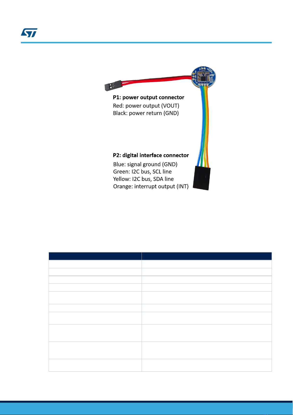
The receiver module must be connected to the dongle as shown in Figure 7a: the P2 connector of the receiver
engages with the corresponding 4 signals of the P2 connector of the dongle. The communication over the I2C bus
is possible only if the STWLC68JRH chip of the receiver is powered: when not placed on a transmitter, the
receiver module can be powered through VOUT by wiring it to the VBUS pin of P2 (Figure 7b). This way of
powering the receiver module is also required during OTP memory flashing.
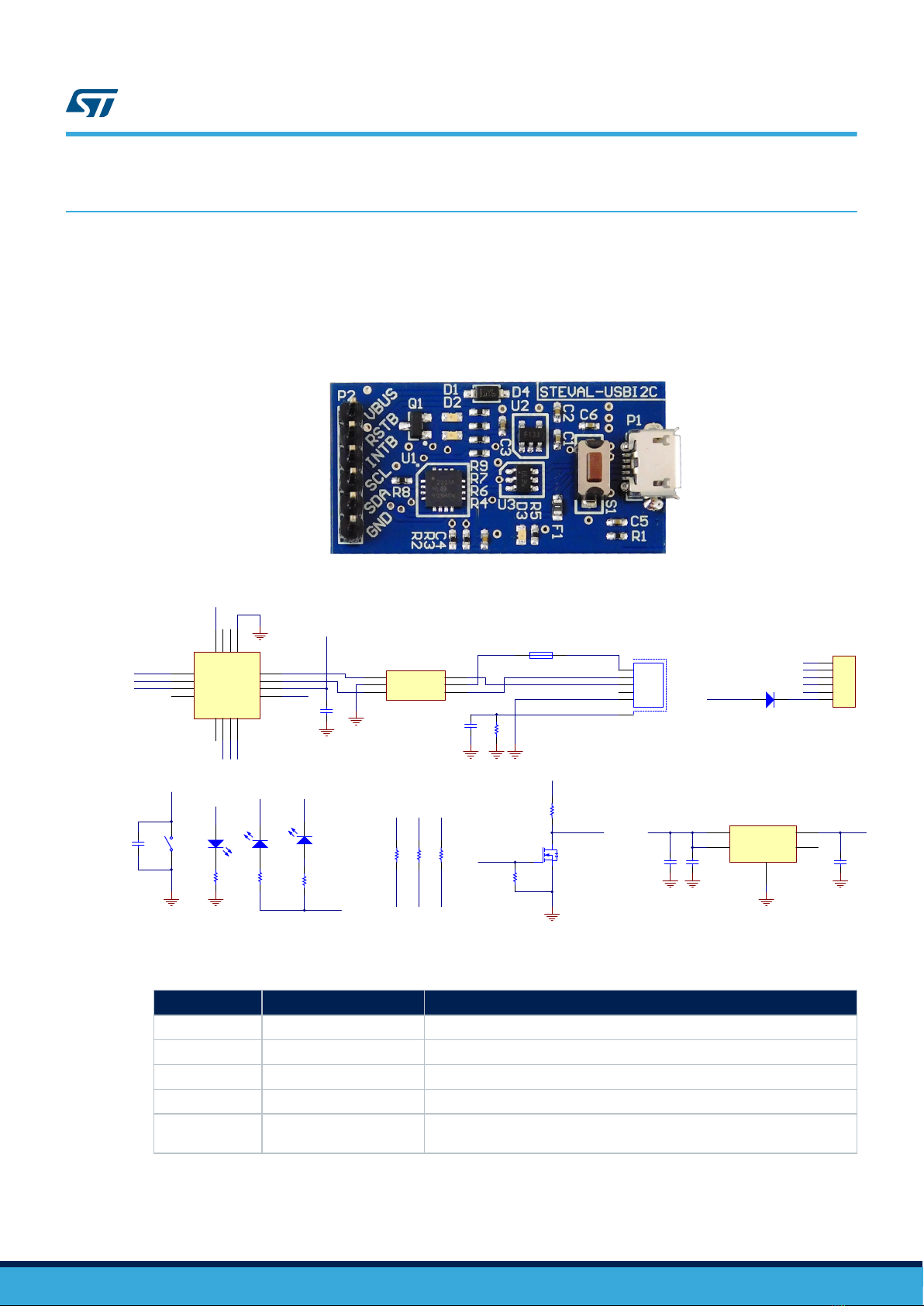
Figure 7. Connection between receiver module and dongle
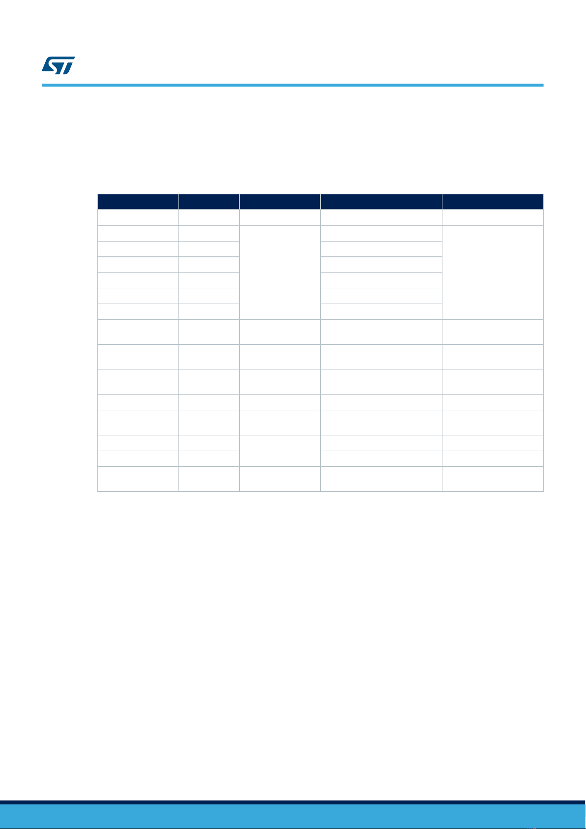
Table 5. USB-to-I2C bridging dongle bill of material
Component Value Description Part Number Manufacturer
C1, C5, C6 100nF ±10% MLCC, X7R, 50V,
0402 GCM155R71H104KE02D Murata
C2 1uF ±10% MLCC, X7R, 25V,
0402 GRM155R61E105KA12D Murata
C3 2.2uF ±20% MLCC, X7R, 6.3V,
0402 GRM155R60J225ME95D Murata
C4 470nF ±10% MLCC, X7R, 16V,
0402 GRM155R61C474KE01D Murata
D1 Red LED, 0603 150060VS55040 Wurth Elektronik
D2 Green LED, 0603 150060RS55040 Wurth Elektronik
D3 Yellow LED, 0603 150060YS55040 Wurth Elektronik
D4 Schottky diode, 60V,
1A, SOD123 STPS1L60ZFY STMicroelectronics
R1 1M ±5%
Resistor, 0.1W, 0402
R2, R3, R4, R9 4k7 ±5%
R5 470R ±5%
R6, R7 220R ±5%
R8 100k ±5%
Q1 N-channel MOSFET,
25V, 0.6A, SOT23 FDV303N ON-Semi
UM2693
USB to I2C bridging dongle
UM2693 - Rev 1 page 7/18