INSTALLATION MANUAL
ILED Aquarius Circle & H 2.0
Helideck Lighting System
Page 4
Introduction
This manual contains a step by step
description of the assembly of the
TRANBERG® IMT ILED CIRCLE-H 2.0.
Following this manual will ensure a correct
installation of the CIRCLE-H system.
Title and sub-title:
• Title: For example “Step A placing the
mounting plates of the H”, you will
need the contents of the boxes labelled
with an A for Step A.
• Sub-title: For example “Starting tool”,
this explains the action on the current
page.
Contents (top left corner):
• The parts needed for the specic
page. Described with a picture, its item
number and the amount needed for the
current action..
Map (top right corner):
• The action on the page visualized in
a big simplied map that shows the
complete construction of the specic
step.
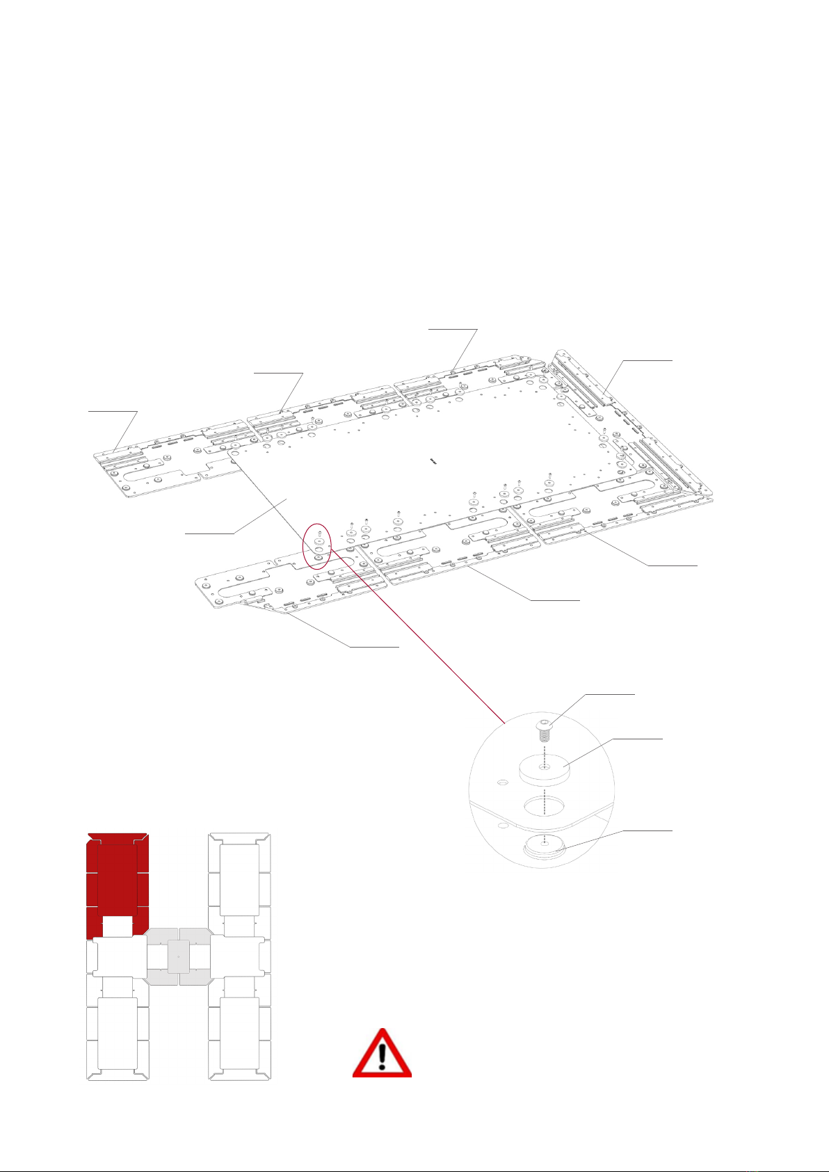
• The used colours:
Red: The section you are contructing
on this page.
Grey: The previously constructed
sections.
White: The sections that will still be
constructed further in the manual.
Overview (middle of the page):
• A 3D-view of the current action.
Tables (not on every page):
• The tables usually explain the
dierence in parts needed for every
dierent helideck size.
Detail (bottom left corner):
• A more detailed view of an action on
the page.
Text:
• Every page has text to explain the
current action step-by-step and what
to pay attention to.
Because the CIRCLE-H 2.0 is a standardized
system useable for many dierent sizes,
shapes and compositions of helidecks
there are 2 versions for working the cables
from the H to the CIRCLE:
• In an angle from the side of the H.
• Straight up from the middle of the H
towards the CIRCLE.
These are described in this manual as a
and b (for example StepA1a and StepA1b)
and are called cable exits. On the bottom
of some of the pages text might tell you
to skip pages to make sure you are on the
pages following the correct cable exit.
Check the drawings to see which cable
exit applies to you.
To explain the commonly used terms on the
pages a small vocabulary has been added
at the end of the manual in appendix A.
In this manual you will nd tables with the
description of both the IMT part numbers
and the R. Stahl Tranberg part numbers.
Please note that all the mounting plates,
cable trays etc. is marked with the IMT part
number for your reference at installation
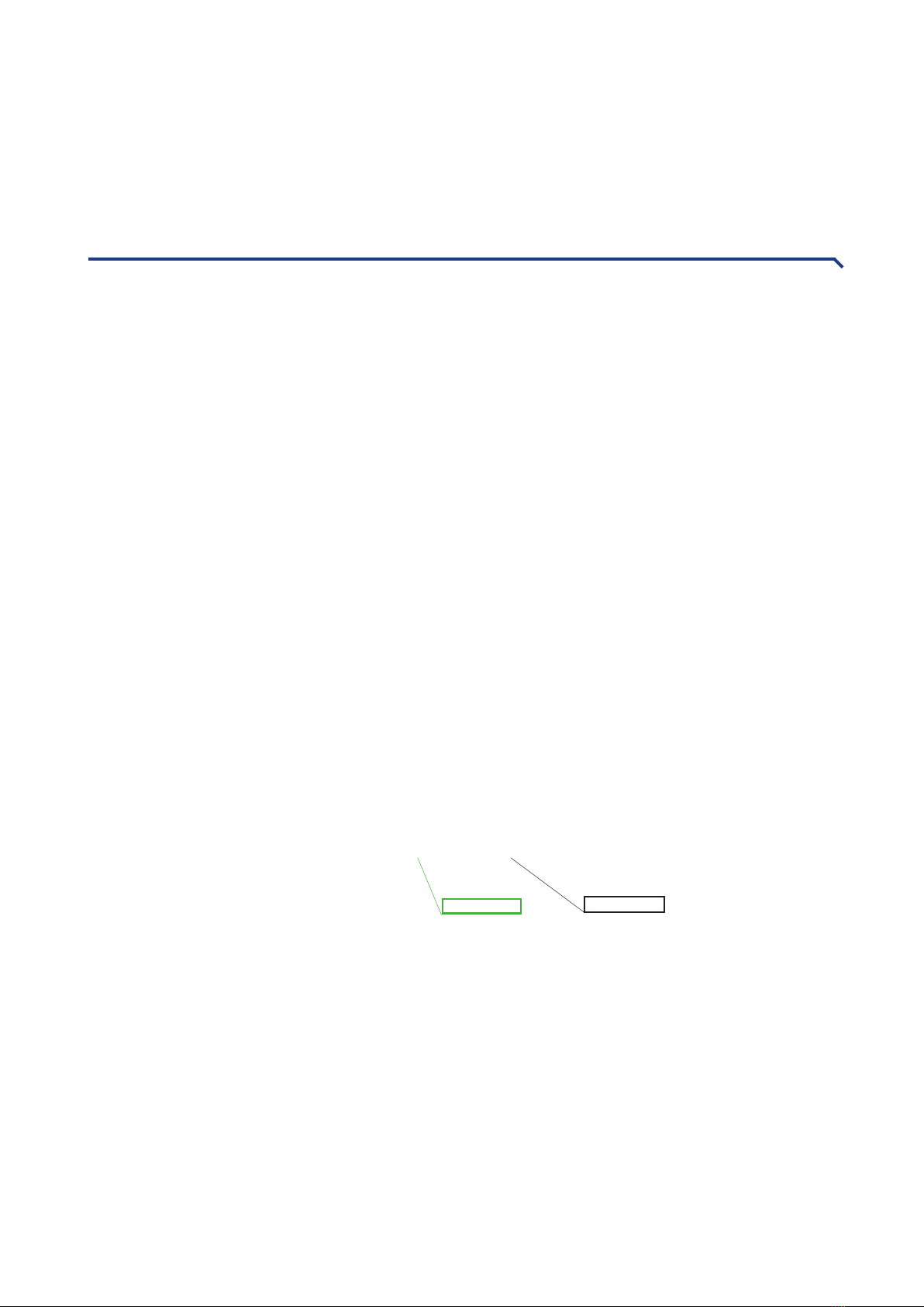
site. The shortage BW stands for Black/
White, example of part number:
902.917 /902.917BW
Green-white Black-white