Stahl ispac 9143 User manual

Typ/Type 9143
Ex i Stromversorgung
I.S. power supply
Betriebsanleitung
Operating Instructions

2
Inhaltsverzeichnis
1
Allgemeine Angaben................................................................................................... 3
1.1
Hersteller ............................................................................................................. 3
1.2
Angaben zu Betriebsanleitung ............................................................................. 3
2
Verwendete Symbole.................................................................................................. 3
3
Sicherheitshinweise .................................................................................................... 3
4
Normenkonformität...................................................................................................... 4
5
Funktion...................................................................................................................... 5
6
Kennzeichnung und technische Daten........................................................................ 5
7
Projektierung............................................................................................................... 6
7.1
Maximal zulässige Umgebungstemperaturen....................................................... 6
8
Anordnung und Montage............................................................................................. 7
8.1
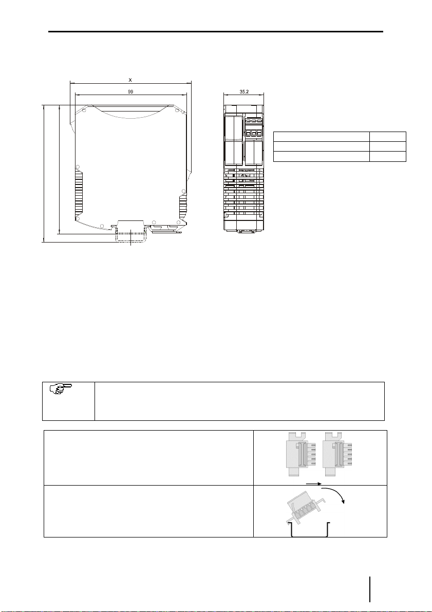
Maßzeichnung ..................................................................................................... 7
8.2
Installation............................................................................................................ 7
8.3
Montage und Demontage..................................................................................... 7
9
Inbetriebnahme........................................................................................................... 9
9.1
Anschlüsse .......................................................................................................... 9
10
Betrieb- und Betriebszustände................................................................................. 9
11
Reparatur und Instandhaltung ................................................................................. 9
12
Zubehör und Ersatzteile......................................................................................... 10
Content
1
General information................................................................................................... 11
1.1
Manufacturer...................................................................................................... 11
2
Symbols used........................................................................................................... 11
3
Safety instructions..................................................................................................... 11
4
Conformity to standards............................................................................................ 12
5
Function.................................................................................................................... 13
6
Marking and technical data ....................................................................................... 13
7
Cabinet installation.................................................................................................... 14
8
Arrangement and fitting............................................................................................. 14
8.1
Dimension drawing ............................................................................................ 14
8.2
Installation.......................................................................................................... 15
8.3
Mounting and dismounting................................................................................. 15
9
Commissioning ......................................................................................................... 17
9.1
Connections....................................................................................................... 17
10
Operation and operational states........................................................................... 17
11
Maintenance and repair......................................................................................... 18
12
Accessories and spare parts.................................................................................. 18
EG-Konformitätserklärung / EC-Declaration of Conformity ............................................... 19
Certification drawing – CSA ............................................................................................. 20

deutsch Betriebsanleitung
Ex i Stromversorgung Typ 9143
3
1 Allgemeine Angaben
1.1 Hersteller
1.2 Angaben zu Betriebsanleitung
ID-Nr. 9143601310
Dokumenten Nr. S-BA-9143-012-de/en-11/2012
HW Revision A
2 Verwendete Symbole
!
Sicherheitshinweise, die unbedingt beachtet werden müssen.
Bei Sicherheitshinweisen auf dem Gerät sind die entsprechenden Angaben
bzw. Sicherheitshinweise der Betriebsanleitung zu beachten!
c
Das Produkt erfüllt die anwendbaren EG-Vorschriften.
e
Die so gekennzeichneten Stromkreise sind, entsprechend der jeweiligen
Kennzeichnung, für explosionsgefährdete Bereiche zugelassen.
Symbol für Eingang
Symbol für Ausgang
Hinweiszeichen: Beschreibt Hinweise und Empfehlungen.
3 Sicherheitshinweise
In diesem Kapitel sind die wichtigsten Sicherheitsmaßnahmen zusammengefasst. Es
ergänzt die entsprechenden Vorschriften, zu deren Studium das verantwortliche Personal
verpflichtet ist.
Bei Arbeiten in explosionsgefährdeten Bereichen hängt die Sicherheit von Personen und
Anlagen von der Einhaltung aller relevanten Sicherheitsvorschriften ab. Das Montage- und
Wartungspersonal trägt deshalb eine besondere Verantwortung. Die Voraussetzung dafür
ist die genaue Kenntnis der geltenden Vorschriften und Bestimmungen.
Bei Errichtung und Betrieb ist Folgendes zu beachten:
•Es gelten die nationalen Montage- und Errichtungsvorschriften (z.B. EN 60079-14).
•Die Ex i Stromversorgung ist außerhalb explosionsgefährdeter Bereiche zu installieren.
•Die Ex i Stromversorgung Typ 9143/10-...-...-10 ist auch für den Betrieb in
explosionsgefährdeten Bereichen der Zone 2 und Zone 22 zugelassen.
•Bei Einsatz in Zone 2, Zone 22 ist die Ex i Stromversorgung in ein Gehäuse einzubauen,
das den Anforderungen der EN 60079-15 genügt.
R. STAHL Schaltgeräte GmbH Telefon: +49 7942 943-0
Am Bahnhof 30 Fax: +49 7942 943-4333
74638 Waldenburg Internet: www.stahl.de
Germany

Betriebsanleitung deutsch
4
Ex i Stromversorgung Typ 9143
•An die eigensicheren Ausgangsstromkreise dürfen eigensichere Geräte der Zone 1 und
21 angeschlossen werden.
•Die Ex i Stromversorgung darf nur an Geräte angeschlossen werden, in denen keine
höheren Spannungen als AC 253 V (50 Hz) auftreten können.
•Die sicherheitstechnischen Werte der / des angeschlossenen Feldgeräte/s müssen mit
den Angaben des Datenblattes bzw. der EG-Baumusterprüfbescheinigung
übereinstimmen.
•Bei Zusammenschaltungen mehrerer aktiver Betriebsmittel in einem eigensicheren
Stromkreis können sich andere sicherheitstechnische Werte ergeben. Hierbei kann die
Eigensicherheit gefährdet werden!
•Die nationalen Sicherheits- und Unfallverhütungsvorschriften
•Die allgemein anerkannten Regeln der Technik
•Die Sicherheitshinweise dieser Betriebsanleitung
•Beschädigungen können den Explosionsschutz aufheben.
Verwenden Sie das Gerät bestimmungsgemäß nur für den zugelassenen Einsatzzweck
(siehe „Verwendung“).
!Warnung
Durch fehlerhaften oder unzulässigen Einsatz sowie das Nichtbeachten der Hinweise
dieser Betriebsanleitung kann der vorgesehene Schutz beeinträchtigt werden, die
Gewährleistung unsererseits wird in diesen Fällen ausgeschlossen.
•Umbauten und Veränderungen am Gerät, die den Explosionsschutz
beeinträchtigen, sind nicht gestattet.
•Das Gerät darf nur in unbeschädigtem, trockenem und sauberem Zustand
eingebaut und betrieben werden.
Sollten Sie Fragen bezüglich der richtigen Handhabung des Gerätes haben, wenden Sie
sich bitte an R. STAHL Schaltgeräte GmbH, Am Bahnhof 30, 74638 Waldenburg,
Germany, Telefon +49-7942-943-0 wenden oder an eine unserer Niederlassungen, siehe
www.stahl-ex.com.
4 Normenkonformität
Bitte entnehmen sie die Normenkonformität der EG-Konformitätserklärung im Anhang
dieses Dokumentes.
Die aktuelle EG-Baumusterprüfbescheinigung können Sie im Internet unter www.stahl.de
herunterladen.

deutsch Betriebsanleitung
Ex i Stromversorgung Typ 9143
5
5 Funktion
Die Ex i Stromversorgungen werden zur eigensicheren Versorgung von Feldgeräten wie
z.B. 3- oder 4-Leiter Messumformer, Magnetventile, Lichtschranken, Reglern eingesetzt.
6 Kennzeichnung und technische Daten
Typbezeichnung
CE-Kennzeichnung
Ex-Kennzeichnung
Umgebungstemperaturbereich
9143/10-***-***-*0
c
0158
e
-20 °C … +70 °C
Global (IECEx) IECEx BVS 12.0009X
Gas
Dust
Mining
9143/10-***-***-10
Ex nA [ib Gb] IIC/IIB T4 Gc
[Ex ib Db] IIIC
[Ex ib Mb] I
9143/10-***-***-20
[Ex ib Gb] IIC/IIB
[Ex ib Db] IIIC
[Ex ib Mb]I
Europe (ATEX) BVS 05 ATEX E 152 X
Gas
Dust
Mining
9143/10-***-***-10
II 3 (2) G Ex nA [ib Gb] IIC/IIB T4 Gc
II (2) D [Ex ib Db] IIIC
I (M2) [Ex ib Mb]I
9143/10-***-***-20
II (2) G [Ex ib Gb] IIC/IIB
II (2) D [Ex ib Db] IIIC
I (M2) [Ex ib Mb]I
Sicherheitstechnische Daten
Typ 9143/10-…-…-*0
065-200
099-220
104-220
114-200
124-150
156-065
156-160
187-050
244-060
max. Spannung U
o
[V]
6,5 9,9 10,4 11,4 12,4 15,6 15,6 18,7 24,4
max. Strom I
o
[mA] 200 220 220 200 150 65 160 50 70
max. Leistung P
o
[W]
1,3 2,178 2,288 2,28 1,86 1,014 2,496 0,935 1,464
max. äußere
Kapazität C
o
IIC [µF]
Kapazität C
o
IIB [µF]
25
570
3
20,2
2,4
16,8
1,64
11,2
1,24
7,9
0,497
3,03
---
3,03
0,27
1,64
-
0,67
Induktivität L
o
IIC [mH]
Induktivität L
o
IIB [mH]
0,82
3,71 0,3
1,7 0,24
1,5 0,16
1,4 0,17
2,08 0,445
11,2 ---
0,351 0,06
15,5 -
0,2
innere Kapazität, C
i
/ Induktivität, L
i
Isolationsspannung U
m
vernachlässigbar
253 V AC
Weitere Angaben und Wertekombinationen siehe EG-Baumusterprüfbescheinigung
Technische Daten (Auszug aus dem Datenblatt)
Hilfsenergie
Variante 9143/10-...-...-10
Variante 9143/10-…-…-20
24V AC/DC
85…230V AC
Umgebungsbedingungen
Betriebstemperatur -20...+70 °C
Lagertemperatur -40...+80 °C
relative Feuchte (keine Betauung) < 95 %
Weitere technische Daten sind dem aktuellen Datenblatt zu entnehmen.
Bei anderen vom Standard abweichenden Betriebsbedingungen nehmen Sie bitte Rücksprache
mit dem Hersteller.

Betriebsanleitung deutsch
6
Ex i Stromversorgung Typ 9143
7 Geräteaufbau
# Beschreibung
1
Schwarze Klemme Anschlussklemmen für den sicheren
Bereich
2
LED „PWR“, grün Anzeige Hilfsenergie
4
Blaue Klemme Anschlussklemmen für den Ex-
Bereich
21
Drehregler „U
A
“ Zu Einstellung der Leerlaufspannung
8 Projektierung
8.1 Maximal zulässige Umgebungstemperaturen
Die Geräte der Reihe ISpac sind über einen weiten Temperaturbereich einsetzbar. Je nach
Geräteausführung und Einbaubedingung ergeben sich unterschiedliche, maximal zulässige
Umgebungstemperaturen.
!Warnung
Befolgen sie die Hinweise des Dokuments “ISpac cabinet installation guideline”
•Geräte können durch unzulässig hohe Umgebungstemperaturen ausfallen.
•Es erlischt die Herstellerhaftung und Gewährleistung.
oDer Schaltschrank muss in einer Art aufgebaut sein, der es erlaubt das Gerät im
spezifizierten Temperaturbereich zu betreiben.
Das Dokument ist verfügbar unter: www.stahl-ex.com.

deutsch Betriebsanleitung
Ex i Stromversorgung Typ 9143
7
9 Anordnung und Montage
9.1 Maßzeichnung
9.2 Installation
Die Ex i Stromversorgung Typ 9143/10-...-...-10 ist auch für den Betrieb in
explosionsgefährdeten Bereichen der Zone 2 und Zone 22 zugelassen. Bei Einsatz in Zone
2, Zone 22 ist die Ex i Stromversorgung in ein Gehäuse einzubauen, das den
Anforderungen der EN 60079-15 genügt.
Das Ex i Stromversorgung Typ 9143/10-…-…-20 ist außerhalb explosionsgefährdeter
Bereiche zu installieren.
9.3 Montage und Demontage
9.3.1 Montage / Demontage pac-Bus
Der pac-Bus ist ein Zubehör, dass die Verdrahtung der Hilfsenergie und das
Auslesen der Sammelfehlermeldung vereinfacht.
Die Komponenten für den pac-Bus Typ 9194 müssen separat bestellt
werden.
Gewünschte Anzahl der pac-Bus-Elemente
zusammenstecken.
pac-Bus-Elemente auf Hutschiene aufrasten.
Maß X
Schraubklemmen 108 mm
Federzugklemmen 128 mm
114,5
1
2
2

Betriebsanleitung deutsch
8
Ex i Stromversorgung Typ 9143
Klemmenset am Anfang und am Ende
einstecken.
pac-Bus ist montiert.
9.3.2 Montage / Demontage auf Hutschiene
Montage
Beim Aufschwenken des Geräts auf die Hutschiene darauf achten, dass es
nicht verkantet.
Gerät an die Hutschiene ansetzen. Die
Aussparung des Gehäuses muss dabei auf die
Außenkante der Hutschiene gesetzt werden.
Gerät auf Hutschiene aufrasten.
Demontage
Fußriegel (1) mit dem Schraubendreher etwas
herausziehen.
Gerät herausschwenken.
9.3.3 Montage / Demontage abziehbare Klemmen
Alle Geräte sind mit abziehbaren Klemmen ausgestattet.
Demontage
Schraubendreher hinter Klemme ansetzen.
Klemme herausdrücken.
Montage
Klemme in Gerät stecken, bis Klemme einrastet.

deutsch Betriebsanleitung
Ex i Stromversorgung Typ 9143
9
10 Inbetriebnahme
10.1 Anschlüsse
Typen 9143/10-***-***-10
Typen 9143/10-***-***-20
11 Betrieb- und Betriebszustände
Bevor Sie das Gerät in Betrieb nehmen, stellen Sie sicher, dass
•das Gerät vorschriftsmäßig installiert wurde
•das Gerät nicht beschädigt ist
•die Kabel ordnungsgemäß angeschlossen sind
12 Reparatur und Instandhaltung
Es wird empfohlen, Reparaturen an unseren Geräten ausschließlich durch uns durchführen
zu lassen. In Ausnahmefällen kann die Reparatur auch durch eine andere, zugelassene
Stelle erfolgen.
Die Geräte sind wartungsfrei.
Fehlersuchplan:
Fehlererkennung Fehlerursache Fehlerbehebung
LED „PWR“ erloschen - Hilfsenergie ausgefallen
- Gerätesicherung defekt
- Hilfsenergieversorgung verpolt
Hilfsenergieversorgung kontrollieren.
Bei defekter Sicherung das Gerät zur Reparatur
geben.
Korrekte Polung herstellen
Keine
Ausgangsspannung,
LED „PWR“ leuchtet
Eingangswiderstand des Verbrauchers zu
gering, Strombegrenzung der
Stromversorgung aktiviert
Wert für maximalen Nennstrom beachten,
Verbraucher entsprechend der Nennwerte
auswählen
+
-
24 V
pac-bus
L/7
N/9
LF
24 V DC/AC
+
-
10+
11-
Hazardousarea
1
Sicherer Bereich
Safearea
Ex-Bereich
R
L
L
N
115/230VAC
10+
11-
1
Safearea
R
L
~
~
7
9
L/7
N/9 85 ... 230V AC
24 V
-
+

Betriebsanleitung deutsch
10
Ex i Stromversorgung Typ 9143
Führen die beschriebenen Vorgehensweisen nicht zum gewünschten Erfolg, wenden Sie
sich bitte an unsere nächste Vertriebsniederlassung. Zur schnellen Bearbeitung benötigt
diese von Ihnen folgende Angaben:
•Typ und Seriennummer,
•Kaufdaten,
•Fehlerbeschreibung,
•Einsatzzweck (insbesondere Eingangs-/Ausgangsbeschaltung)
13 Zubehör und Ersatzteile
Verwenden Sie nur Original-Ersatzteile der Fa. R. STAHL Schaltgeräte GmbH.

deutsch Betriebsanleitung
Ex i Stromversorgung Typ 9143
11
1 General information
1.1 Manufacturer
Information regarding the operating instruction:
ID-Nr. 9143601310
Document number S-BA-9143-012-de/en-11/2012
Hardware revision A
2 Symbols used
3 Safety instructions
The most important safety instructions are summarised in this chapter. It is intended to
supplement the relevant regulations which must be studied by the personnel responsible.
When working in hazardous areas, the safety of personnel and plant depends on
complying with all relevant safety regulations. Assembly and maintenance staff working on
installations therefore have a particular responsibility. The precondition for this is an
accurate knowledge of the applicable regulations and provisions.
When installing and operating the device, the following are to be observed:
•The national installation and assembly regulations (e.g. EN 60079-14) apply.
•The I.S. power supply is to be installed outside of hazardous areas.
•Type 9143/10-…-…-10 I.S. power supply are also approved for operation in Zone 2,
Zone 22 hazardous areas.
•In the case of operation in Zone 2 and 22, the I.S. power supply must be fitted in an
enclosure which complies with the requirements of EN 60079-15.
R. STAHL Schaltgeräte GmbH Phone: +49 7942 943-0
Am Bahnhof 30 Fax: +49 7942 943-4333
74638 Waldenburg Internet: www.stahl.de
Germany
!
Safety note, which is essential to take note.
With safety note on the equipment the appropriate data and/or safety reference
of the manual are to be considered!
c
The device complies with the applicable EC standards.
e
Electric circuits marked with the symbol are certified, according to the respective
marking, for hazardous locations.
Symbol for input
Symbol for output
Information sign: Provides a note or recommendation.

Operating Instructions english
12
Vibration Transducer Supply Unit Type 9147
•Zone 1 and 21 intrinsically safe devices may be connected to the intrinsically safe
signal circuits.
•The I.S. power supply may only be connected to devices which will not be subjected
to voltages higher than AC 253 V (50 Hz).
•The safe maximum values of the connected field device(s) must correspond to the
values of the data sheet or the EC-type examination certificate.
•Interconnecting several active devices in an intrinsic safety circuit may result in other
safe maximum values. This could endanger the intrinsic safety!
•National safety and accident prevention regulations
•The generally recognised technical regulations
•The safety guidelines in these operating instructions
•Any damage can compromise and even neutralise the explosion protection.
Use the device in accordance with the regulations and for its intended purpose only (see
“Function”).
!Warning
With incorrect or unauthorized use or non-compliance with these instructions the
intended protection can be impaired, the warranty provision is invalidate on our part in
these cases.
oNo changes to the devices or components impairing their explosion protection are
permitted.
oFurthermore, the device may only be operated if it is undamaged, dry and clean.
Should there be any question about the correct handling of the module, please contact R.
STAHL Schaltgeräte GmbH, Am Bahnhof 30, 74638 Waldenburg, Germany, telephone
+49-7942-943-0, or contact one of our offices or representatives see www.stahl-ex.com.
4 Conformity to standards
The information about the conformity to standards can be found in the manufacturer’s
declaration of conformity in the appendix of this document.
The current EC-Type Examination Certificate can be downloaded from the Internet
www.stahl-ex.com .

english Operating instructions
I.S. Power Supply Type 9143
13
5 Function
I.S. power supplies are used to provide intrinsically safe power to field devices such as 3-
wire or 4-wire transmitters, solenoid valves, photoelectric sensors and controllers.
6 Marking and technical data
Type designation
CE marking
Ex marking
Ambient temperature range
9143/10-***-***-*0
c
0158
e
-20 °C … +70 °C
Global (IECEx) IECEx BVS 12.0009X
Gas
Dust
Mining
9143/10-***-***-10
Ex nA [ib Gb] IIC/IIB T4 Gc
[Ex ib Db] IIIC
[Ex ib Mb] I
9143/10-***-***-20
[Ex ib Gb] IIC/IIB
[Ex ib Db] IIIC
[Ex ib Mb]I
Europe (ATEX) BVS 05 ATEX E 152 X
Gas
Dust
Mining
9143/10-***-***-10
II 3 (2) G Ex nA [ib Gb] IIC/IIB T4 Gc
II (2) D [Ex ib Db] IIIC
I (M2) [Ex ib Mb]I
9143/10-***-***-20
II (2) G [Ex ib Gb] IIC/IIB
II (2) D [Ex ib Db] IIIC
I (M2) [Ex ib Mb]I
Safety data
Type 9143/10-…-…-
*0
065-200
099-220
104-220
114-200
124-150
156-065
156-160
187-050
244-060
max. voltage U
o
[V]
6,5 9,9 10,4 11,4 12,4 15,6 15,6 18,7 24,4
max. current I
o
[mA]
200 220 220 200 150 65 160 50 70
max. power P
o
[W]
1,3 2,178 2,288 2,28 1,86 1,014 2,496 0,935 1,464
max.external
capacitanceC
o
IIC [µF]
capacitanceC
o
IIB[µF]
25
570
3
20,2
2,4
16,8
1,64
11,2
1,24
7,9
0,497
3,03
---
3,03
0,27
1,64
-
0,67
inductance L
o
IIC[mH]
inductance L
o
IIB[mH]
0,82
3,71 0,3
1,7 0,24
1,5 0,16
1,4 0,17
2,08 0,445
11,2 ---
0,351 0,06
15,5 -
0,2
internal capacitance, C
i
/ inductance, L
i
Insulation voltage U
m
negligible
253 V AC
See EC-type examination certificate for further information and value combinations
Technical data (extract from the data sheet)
Power supply
Version 9143/10-...-...-10
Version 9143/10-…-…-20
24V AC/DC
85…230V AC
Ambient conditions
Max. operating temperature -20...+70 °C
Storage temperature -40...+80 °C
Relative humidity (no condensation) < 95 %
Additional technical data can be found in the current data sheet.
Please consult with the manufacturer before operating under conditions which deviate
from the standard operating conditions.

Operating instructions english
14
I.S. Power Supply Type 9143
7 Device description
# Description
1
Black terminals Connection terminals for the safe area
2
LED „PWR“ Indication of power supply
4
Blue terminals Connection terminals for the
hazardous area (intrinsic safe).
21
Knob “output voltage” Adjustment of output voltage.
8 Cabinet installation
The ISpac isolators can be used over a wide temperature range. Depending on the isolator
version and installation method may result in different maximum ambient temperatures.
!Warning
Follow the instructions of the “ISpac cabinet installation guideline”
•Device may fail because of high ambient temperature.
•The manufacturer’s liability and warranty expire.
oThe cabinet need to be built in a way which allows to operate the device within the
specified temperature range
The cabinet installation guide is available on www.stahl-ex.com.
9 Arrangement and fitting
9.1 Dimension drawing
Size X
Screw terminals 108 mm
Spring clamp terminals 128 mm
114,5
1
2
2

english Operating instructions
I.S. Power Supply Type 9143
15
9.2 Installation
Type 9143/10-…-…-10 I.S. power supply are approved for operation in Zone 2, Zone 22
hazardous areas. In the case of operation in Zone 2 and 22, the I.S. power supply must be
fitted in an enclosure which complies with the requirements of EN 60079-15.
Type 9143/10-…-…-20 I.S. power supply has to be installed outside of the hazardous area.
9.3 Mounting and dismounting
9.3.1 Mounting of pac-Bus
The pac-Bus is an accessory, which facilitates the wiring of the power
supply and the common fault signalization.
The components of the pac-Bus type 9194 need to be ordered separately.
Assemble the required number of pac-Bus
elements.
Snap the pac-Bus segment on the DIN rail.
Assemble the terminal set at the beginning and
the end of the pac-Bus segment.
9.3.2 Mounting / Dismounting on DIN rail with or without pac-Bus
Mounting
Take care that the devices is not canted before it is snapped on the DIN rail.
Put the device on the DIN rail. Take care that the cut out of
the enclosure fits onto the edge of the DIN rail.
Swivel the device until it is snapped on the DIN rail.
Dismounting

Operating instructions english
16
I.S. Power Supply Type 9143
Pull the latch (1) with the screw driver out.
Swivel the device out.
9.3.3 Mounting / Dismounting detachable terminals
All devices are equipped with detachable terminals.
Dismounting
Place the screw driver between terminal and
enclosure.
Move the screw driver as described.
Mounting
Place the terminal into the terminal slot and press it towards the device until it is locked.

english Operating instructions
I.S. Power Supply Type 9143
17
10 Commissioning
10.1 Connections
Types 9143/10-***-***-10
Types 9143/10-***-***-20
10.2 Settings
The output voltage can be adjusted in a pre-defined range. The set-up can be arranged by
means of the knob on the front of the device. The individual range is indicated on the
device.
11 Operation and operational states
Before commissioning the device, please ensure that:
•the device was installed in accordance with the regulations
•the device is not damaged
•the cables are properly connected
+
-
24 V
pac-bus
N/9
L/7
LF
24 V DC/AC
+
-
10+
11-
Hazardousarea
1
Sicherer Bereich
Safearea
Ex-Bereich
R
L
L
N
115/230VAC
10+
11-
1
Safearea
R
L
~
~
7
9
L/7
N/9 85 ... 230V AC

Operating instructions english
18
I.S. Power Supply Type 9143
12 Maintenance and repair
It is recommended that all repairs to our devices be carried out by R. STAHL. In
exceptional cases, repair may be performed by approved third-parties.
The devices are maintenance-free.
Troubleshooting chart:
Error detection Cause of error Corrective action
“PWR” LED does not lit Power supply failure
Device fuse is defective
Polarity reversal
Check power supply.
If device fuse is defective, send device in for
repair.
Connect the power acc. to operating guide
Output voltage
dropped, LED “PWR”
on
Load resistance is too low, current
limitation of the power supply is activated Check the maximum nominal current, select a
load resistance acc. to the specification
If the procedure described above does not obtain the desired result, please contact your
local R.STAHL sales and service representative. In order to quickly process your request,
please provide us with the following information:
•Type and serial number,
•Purchase date(s),
•Description of the error,
•Application description (particularly the configuration of the
input/output circuitry)
13 Accessories and spare parts
Use only original spare parts from R. STAHL Schaltgeräte GmbH.

EG-Konformitätserklärung / EC-Declaration of Conformity

Certification drawing – CSA
Table of contents
Languages:
Other Stahl Power Supply manuals

Stahl
Stahl 9143 Series User manual

Stahl
Stahl 9143/10-065-200-10 User manual

Stahl
Stahl 9412/00-300-10 User manual

Stahl
Stahl 9162 Series User manual

Stahl
Stahl 9412 Series User manual

Stahl
Stahl ISpac 9162 User manual

Stahl
Stahl 9162 Series User manual

Stahl
Stahl 9160/19-11-10k User manual

Stahl
Stahl Series 9160 User manual

Stahl
Stahl Series 9160 User manual