Stahl Series 9160 User manual

Operating Instructions english
2Transmitter Supply Unit Type 9160
Inhaltsverzeichnis
1Allgemeine Angaben................................................................................................... 3
1.1 Hersteller.............................................................................................................3
1.2 Angaben zu Betriebsanleitung .............................................................................3
2Verwendete Symbole.................................................................................................. 3
3Sicherheitshinweise .................................................................................................... 3
4Normenkonformität...................................................................................................... 4
5Funktion...................................................................................................................... 4
6Kennzeichnung und technische Daten ........................................................................ 5
7Geräteaufbau..............................................................................................................6
8Projektierung............................................................................................................... 6
8.1 Maximal zulässige Umgebungstemperaturen....................................................... 6
9Anordnung und Montage............................................................................................. 6
9.1 Maßzeichnung ..................................................................................................... 6
9.2 Installation............................................................................................................7
9.3 Montage und Demontage..................................................................................... 7
10 Inbetriebnahme ....................................................................................................... 9
10.1 Anschlüsse.......................................................................................................9
10.2 Einstellungen.................................................................................................. 10
Betrieb- und Betriebszustände......................................................................................... 11
11 Reparatur und Instandhaltung ............................................................................... 11
12 Zubehör und Ersatzteile......................................................................................... 11
Content
1General information................................................................................................... 12
1.1 Manufacturer...................................................................................................... 12
2Symbols used........................................................................................................... 12
3Safety instructions..................................................................................................... 12
4Conformity to standards............................................................................................ 13
5Function.................................................................................................................... 13
6Marking and technical data ....................................................................................... 14
7Device description..................................................................................................... 15
8Cabinet installation.................................................................................................... 15
9Arrangement and fitting............................................................................................. 15
9.1Dimension drawing ............................................................................................ 15
9.2 Installation.......................................................................................................... 16
9.3 Mounting and dismounting................................................................................. 16
10 Commissioning...................................................................................................... 18
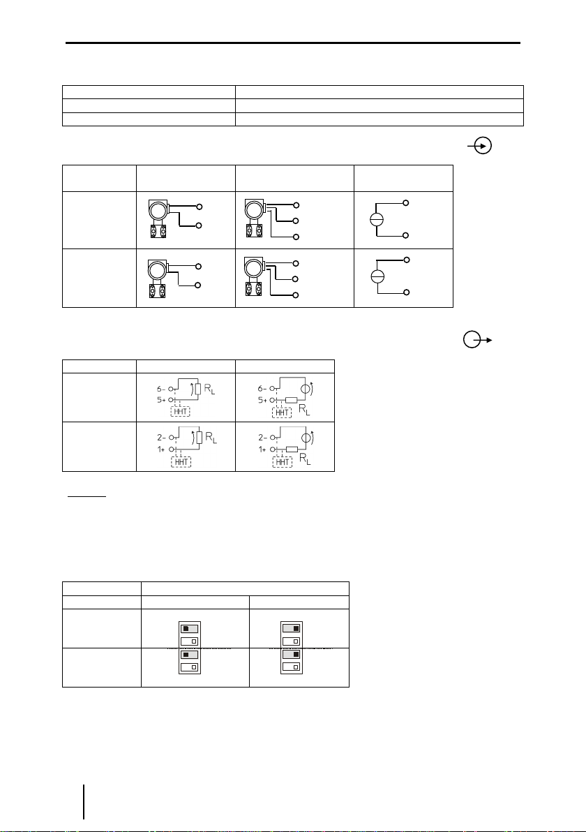
10.1 Connections ................................................................................................... 18
10.2 Settings.......................................................................................................... 19
11 Operation and operational states........................................................................... 20
12 Maintenance and repair......................................................................................... 20
13 Accessories and spare parts.................................................................................. 20
EC-Type Examination Certificate ..................................................................................... 21

english Operating Instructions
Transmitter Supply Unit Type 9160 3
1 Allgemeine Angaben
1.1 Hersteller
1.2 Angaben zu Betriebsanleitung
ID-Nr. 9160617310
Pub-Nr. S-BA-9160-000-de/en-xx/2013
HW-Revision F
2 Verwendete Symbole
!
Gefahr
c
Das Produkt erfüllt die anwendbaren EG-Vorschriften.
e
Stromkreise sind für explosionsgefährdete Bereiche zugelassen
Eingang
Ausgang
Hinweise und Empfehlungen
3 Sicherheitshinweise
In diesem Kapitel sind die wichtigsten Sicherheitsmaßnahmen zusammengefasst. Es
ergänzt die entsprechenden Vorschriften, zu deren Studium das verantwortliche Personal
verpflichtet ist.
Bei Arbeiten in explosionsgefährdeten Bereichen hängt die Sicherheit von Personen und
Anlagen von der Einhaltung aller relevanten Sicherheitsvorschriften ab. Das Montage- und
Wartungspersonal trägt deshalb eine besondere Verantwortung. Die Voraussetzung dafür
ist die genaue Kenntnis der geltenden Vorschriften und Bestimmungen.
Bei Errichtung und Betrieb ist Folgendes zu beachten:
Bei SIL Anwendungen FMEDA Report SIL STAHL 05/08-34 R008 und das
Sicherheitshandbuch beachten.
Das Gerät ist in Zone 2, Zone 22 oder außerhalb explosionsgefährdeter Bereiche zu
installieren.
Bei Einsatz in Zone 2 oder Zone 22 ist das Gerät in ein Gehäuse einzubauen, das den
Anforderungen der IEC/EN 60079-15 genügt.
An die eigensicheren Signalstromkreise dürfen, auch bei Einsatz in Zone 2 und Zone 22,
eigensichere Geräte der Zonen 1, 0, 21 und 20 angeschlossen werden
R. STAHL Schaltgeräte GmbH
Telefon: +49 7942 943-0
Am Bahnhof 30
Fax: +49 7942 943-4333
74638 Waldenburg
Internet: www.stahl.de
Germany

Operating Instructions english
4Transmitter Supply Unit Type 9160
Das Gerät darf nur an Betriebsmittel angeschlossen werden, in denen keine höheren
Spannungen als AC 253 V (50 Hz) auftreten können.
Die sicherheitstechnischen Werte der angeschlossenen Feldgeräte müssen mit den
Angaben des Datenblattes bzw. der EG-Baumusterprüfbescheinigung übereinstimmen.
Bei Zusammenschaltungen mehrerer aktiver Betriebsmittel in einem eigensicheren
Stromkreis können sich andere sicherheitstechnische Werte ergeben. Hierbei kann die
Eigensicherheit gefährdet werden!
Die Sicherheitshinweise dieser Betriebsanleitung.
Beschädigungen können den Explosionsschutz aufheben.
Verwenden Sie das Gerät bestimmungsgemäß, nur für den zugelassenen Einsatzzweck
(siehe „Funktion“).
Durch fehlerhaften oder unzulässigen Einsatz sowie das Nichtbeachten der Hinweise
dieser Betriebsanleitung kann der vorgesehene Schutz beeinträchtigt werden, die
Gewährleistung unsererseits wird in diesen Fällen ausgeschlossen.
Umbauten und Veränderungen am Gerät, die den Explosionsschutz beeinträchtigen,
sind nicht gestattet.
Das Gerät darf nur in unbeschädigtem, trockenem und sauberem Zustand eingebaut
und betrieben werden.
Sollten Sie Fragen bezüglich der richtigen Handhabung des Gerätes haben, wenden Sie
sich bitte an R. STAHL Schaltgeräte GmbH, Am Bahnhof 30, 74638 Waldenburg,
Germany, Telefon +49-7942-943-0 wenden oder an eine unserer Niederlassungen, siehe
www.stahl-ex.com.
4 Normenkonformität
Bitte entnehmen sie die Normenkonformität der EG-Konformitätserklärung im Anhang
dieses Dokumentes.
Die aktuelle EG-Baumusterprüfbescheinigung können Sie im Internet unter www.stahl.de
herunterladen.
5 Funktion
Die Messumformerspeisegeräte werden zum eigensicheren Betrieb von 2- und 3-Leiter-
Messumformern oder zum Anschluss an eigensichere mA-Quellen eingesetzt.
Die 2- und 3-Leiter-Messumformer werden vom Messumformerspeisegerät mit Hilfsenergie
versorgt.
Die Geräte übertragen ein überlagertes HART-Kommunikationssignal bidirektional.

english Operating Instructions
Transmitter Supply Unit Type 9160 5
6 Kennzeichnung und technische Daten
Hersteller
Typbezeichnung
CE-Kennzeichnung
ATEX Kennzeichnung Explosionsschutz
und
Prüfstelle und Bescheinigungsnummer
IECEx Kennzeichnung Explosionsschutz
Prüfstelle und Bescheinigungsnummer
Umgebungstemperaturbereich
R. STAHL
9160/**-1*-1*
c0158
eII 3 (1)G Ex nA nC [ia Ga] IIC T4 Gc
eII (1) D [Ex ia Da] IIIC
DMT 03 ATEX E 010 X
Ex nA nC [ia Ga] IIC T4 Gc
[Ex ia Da] IIIC
IECEx BVS 08.0050X
-40 °C … +60 (+70) °C
Sicherheitstechnische Daten (2-Leiter Betrieb)
Typ
9160/**-1*-1*
9160/14-1*-1*
max. Spannung, Uo
max. Strom, Io
max. Leistung, Po
innere Kapazität, Ci/ Induktivität, Li
max. anschließbare Kapazität, CoIIC / IIB
max. anschließbare Induktivität, Lo IIC / IIB
Isolationsspannung Um
27 V
88 mA
576 mW
vernachlässigbar
90 nF / 705 nF
2,3 mH / 14 mH
253 V
27 V
112,5 mA
731 mW
vernachlässigbar
90 nF / 705 nF
0,31 mH / 9,2 mH
253 V
Weitere Angaben und Wertekombinationen siehe EG-Baumusterprüfbescheinigung
Technische Daten (Auszug aus dem Datenblatt)
Typ
9160/**-1*-1*
9160/14-1*-1*
Hilfsenergie
Nennspannung UN
24 VDC
24 VDC
Nennstrom (bei UNund IAmax) 1 / 2 Kanäle
70 mA / 125 mA
95 mA
Leistungsaufnahme (bei UNund IAmax)
1 / 2 Kanäle
1.7 W / 3 W
2,3 W
Ex i Eingang
Speisespannung für Messumformer
Eingangssignalbereich
16 V
0/4…20 mA
18 V
0/4…20 mA
Ausgang
Bereich für Lastwiderstand (Bürde)
für Varianten 9160/**-11-** (Quelle)
Ausgangssignalbereich
600
0/4...20 mA
Umgebungsbedingungen
Betriebstemperatur
-40...+60 (+70) °C (siehe Abschnitt Projektierung)
Lagertemperatur
-40...+80 °C
relative Feuchte (keine Betauung)
< 95 %
Weitere technische Daten sind dem aktuellen Datenblatt zu entnehmen.
Bei anderen vom Standard abweichenden Betriebsbedingungen nehmen Sie bitte
Rücksprache mit dem Hersteller.

Operating Instructions english
6Transmitter Supply Unit Type 9160
7 Geräteaufbau
#
Beschreibung
1
Schwarze Klemmen
Anschlussklemmen für den sicheren Bereich
2
LED „PWR“, grün
Anzeige Hilfsenergie
3
LED „LF1“, rot
Anzeige Leitungsfehlererkennung für Kanal 1
4
LED „LF2“, rot
Anzeige Leitungsfehlererkennung für Kanal 2
5
DIP- Schalter „LF1“
Aktivierung der Leitungsfehlererkennung für
Kanal 1
7
DIP- Schalter „LF2“
Aktivierung der Leitungsfehlererkennung für
Kanal 2
9
Blaue Klemmen
Anschlussklemmen für den Ex-Bereich
(eigensicher Ex i)
8 Projektierung
8.1 Maximal zulässige Umgebungstemperaturen
Die Geräte der Reihe ISpac sind über einen weiten Temperaturbereich einsetzbar. Je nach
Geräteausführung und Einbaubedingung ergeben sich unterschiedliche, maximal zulässige
Umgebungstemperaturen.
Achtung
Befolgen sie die Hinweise des Dokuments “ISpac cabinet installation guideline”
Geräte können durch unzulässig hohe Umgebungstemperaturen ausfallen.
Es erlischt die Herstellerhaftung und Gewährleistung.
oDer Schaltschrank muss in einer Art aufgebaut sein, der es erlaubt das Gerät im
spezifizierten Temperaturbereich zu betreiben.
Das Dokument ist verfügbar unter: www.stahl-ex.com.
9 Anordnung und Montage
9.1 Maßzeichnung
Maß X
Schraubklemmen
108 mm
Federzugklemmen
128 mm

english Operating Instructions
Transmitter Supply Unit Type 9160 7
9.2 Installation
Das Gerät ist in der Zone 2, 22 oder außerhalb explosionsgefährdeter Bereiche zu
installieren.
Bei Betrieb in Zone 2, 22 ist das Gerät in ein Gehäuse einzubauen, das den
Anforderungen der EN 60079-15 genügt (z.B. in ein Gehäuse Typ 8146 der
Firma R. STAHL Schaltgeräte GmbH).
9.3 Montage und Demontage
9.3.1. Montage / Demontage pac-Bus
Der pac-Bus ist ein Zubehör, dass die Verdrahtung der Hilfsenergie und das
Auslesen der Sammelfehlermeldung vereinfacht.
Die Komponenten für den pac-Bus Typ 9194 müssen separat bestellt
werden.
Gewünschte Anzahl der pac-Bus-Elemente
zusammenstecken.
pac-Bus-Elemente auf Hutschiene aufrasten.
Klemmenset am Anfang und am Ende
einstecken.
pac-Bus ist montiert.
9.3.2. Montage / Demontage auf Hutschiene
Montage
Beim Aufschwenken des Geräts auf die Hutschiene darauf achten, dass es
nicht verkantet.
Gerät an die Hutschiene ansetzen. Die
Aussparung des Gehäuses muss dabei auf die
Außenkante der Hutschiene gesetzt werden.
Gerät auf Hutschiene aufrasten.

Operating Instructions english
8Transmitter Supply Unit Type 9160
Demontage
Fußriegel (1) mit dem Schraubendreher etwas
herausziehen.
Gerät herausschwenken.
9.3.3. Montage / Demontage auf pac-Träger
Montage
Schwarze und grüne Klemmen entfernen.
Bei einkanaligen Geräten: Abdeckung im
Klemmenschacht 2 entfernen (zwischen
schwarzer und grüner Klemme)
Gerät auf pac-Träger aufsetzen. Die Aussparung
des Gehäuses muss dabei auf die Außenkante
des pac-Trägers gesetzt werden. Danach das
Gerät einschwenken bis roter Rasthebel
einrastet.
Der rote Rasthebel muss eingerastet sein.
Demontage
Rasthebel (1) mit einem Schraubendreher
ausschwenken.
Gerät wird aus dem Steckplatz geschoben (2).

english Operating Instructions
Transmitter Supply Unit Type 9160 9
9.3.4. Montage / Demontage abziehbare Klemmen
Alle Geräte sind mit abziehbaren Klemmen ausgestattet.
Demontage
Schraubendreher hinter Klemme ansetzen.
Klemme herausdrücken.
Montage
Klemme in Gerät stecken, bis Klemme einrastet.
10 Inbetriebnahme
10.1 Anschlüsse
Typen 9160/**-1*-1*
Typen 9160/19-1*-1*
(ein Eingang, zwei
Ausgänge)
)* Varianten 9160/**-**-10 ohne
Leitungsfehlererkennung und -meldung
mit HART
mit HART
mit HART
mit HART
LF )*
LF )*
LF )*
LF )*

Operating Instructions english
10 Transmitter Supply Unit Type 9160
Anschluss der Speisung (grüne Klemme 9-/7+):
Art der Versorgung
Anschluss
Direkte Versorgung des Gerätes
Grüne Klemme mit den PIN’s 9- und 7+
Versorgung über pac-Bus
Siehe Kapitel 10
Eingangsbeschaltung (blaue Klemmen mit den PINs 10,11,12 und 13,14,15):
Zwei-Leiter-
Messumformer
Drei-Leiter-
Messumformer
mA-Quelle
4-Leiter-MU
Kanal 2
Kanal 1
Ausgangsbeschaltung (schwarze Klemmen mit den PINs 1,2,3 und 4,5,6)
9160/...
/**-11-1*
/*3-10-1*
Kanal 2
Kanal 1
Hinweis: Für eine funktionierende HART-Kommunikation im Ausgangsstromkreis ist ein
Lastwiderstand (z.B. Eingangswiderstand der Eingangsbaugruppe) von mindestens 250
notwendig. Steht dieser nicht zur Verfügung, kann zusätzlich der interne 221 Widerstand
verwendet werden. Der Anschluss muss dann an den Klemmen 3+/2- bzw. 4+/6- erfolgen.
Die maximale Ausgangslast verringert sich auf 479 .
10.2 Einstellungen
Leitungsfehlererkennung LF
Deaktiviert *
Aktiviert
Kanal 1
Kanal 2
*) Standardeinstellung bei Auslieferung
Die Varianten 9160/**-**-10 verfügen über keine Leitungsfehlererkennung- und –meldung
und damit auch nicht über die entsprechenden DIP-Schalter.
LF1
LF2
ON
OFF
1
2
LF1
LF2
ON
OFF
1
2
14
13 +
12 +
10
12 +
11 -
10
15 -
14
(0..
20
mA)
13 +
+
+
11 -
10 +
15 -
14 +
+
+
-
-
0/4...20mA
0/4...20mA

english Operating Instructions
Transmitter Supply Unit Type 9160 11
Bitte beachten: Die Leitungsfehlererkennung bezieht den Eingang und Ausgang mit ein.
Bei der Gerätevariante 9160/19-..-.. bezieht sich die Fehlererkennung auf den
gemeinsamen Eingang und den entsprechenden Ausgangskanal. Offene Ausgänge führen
deshalb zu einer Fehlermeldung. Nicht genutzte aktive Ausgänge sollten mit einem 250
Ohm Widerstand beschaltet werden.
Die Änderung der DIP-Schalter-Einstellungen ist im Betrieb auch in der Zone 2 und bei
angeschlossenen, eigensicheren Eingangssignalen zulässig.
11 Betrieb- und Betriebszustände
Bevor Sie das Gerät in Betrieb nehmen, stellen Sie sicher, dass
das Gerät vorschriftsmäßig im korrekten Steckplatz installiert wurde
das Gerät nicht beschädigt ist
die Kabel ordnungsgemäß angeschlossen sind
Bei detektierten Leitungsfehler ist Ausgangssignal gleich dem Eingangssignal.
12 Reparatur und Instandhaltung
Reparaturen an den Geräten dürfen ausschließlich durch R. STAHL ausgeführt werden.
Die Geräte sind wartungsfrei.
Fehlersuchplan:
Fehlererkennung
Fehlerursache
Fehlerbehebung
LED „PWR“ erloschen
Hilfsenergie ausgefallen oder
Gerätesicherung defekt
Hilfsenergieversorgung kontrollieren.
Bei defekter Sicherung das Gerät zur Reparatur
geben.
Führen die beschriebenen Vorgehensweisen nicht zum gewünschten Erfolg, wenden Sie
sich bitte an unsere nächste Vertriebsniederlassung. Zur schnellen Bearbeitung benötigt
diese von Ihnen folgende Angaben:
Typ und Seriennummer,
Kaufdaten,
Fehlerbeschreibung,
Einsatzzweck (insbesondere Eingangs-/Ausgangsbeschaltung)
13 Zubehör und Ersatzteile
Verwenden Sie nur Original-Zubehör sowie Original-Ersatzteile der
Fa. R. STAHL Schaltgeräte GmbH

Operating Instructions english
12 Transmitter Supply Unit Type 9160
1 General information
1.1 Manufacturer
1.2 Information regarding the operating instruction
ID-Nr.: 9160617310
Pub-Nr.: S-BA-9160-001-de/en-11/2012
HW-revision F
2 Symbols used
3 Safety instructions
The most important safety instructions are summarised in this chapter. It is intended to
supplement the relevant regulations which must be studied by the personnel responsible.
When working in hazardous areas, the safety of personnel and plant depends on
complying with all relevant safety regulations. Assembly and maintenance staff working on
installations therefore have a particular responsibility. The precondition for this is an
accurate knowledge of the applicable regulations and provisions.
When installing and operating the device, the following are to be observed:
For SIL applications please observe the FMEDA report “SIL STAHL 05/08-34 R008”and
the safety manual.
The apparatus may be installed in Zone 2, Zone 22 or outside the explosion hazard
areas.
If installed in Zone 2 or Zone 22, the apparatus is to be fitted in an enclosure that meets
the requirements of IEC/EN 60079-15.
R. STAHL Schaltgeräte GmbH
Phone: +49 7942 943-0
Am Bahnhof 30
Fax: +49 7942 943-4333
74638 Waldenburg
Internet: www.stahl.de
Germany
!
Danger
c
The device complies with the applicable EC standards.
e
Electric circuits for hazardous locations.
Input
Output
Information sign: Provides a note or recommendation.

english Operating Instructions
Transmitter Supply Unit Type 9160 13
Intrinsically safe devices of Zone 1, 0, 21 and 20 may also be connected to the
intrinsically safe signal circuits by using in Zone 2 or Zone 22.
The apparatus may be connected only to devices in which no voltages higher than 253 V
AC (50 Hz) may occur.
The safe maximum values of the connected field device(s) must correspond to the
values of the data sheet or the EC-type examination certificate.
Interconnecting several active devices in an intrinsic safety circuit may result in other
safe maximum values. This could endanger the intrinsic safety!
The safety guidelines in these operating instructions.
Any damage can invalidate the explosion protection.
Use the device in accordance with the regulations and for its intended purpose only (see
“Function”).
!Warning
With incorrect or unauthorized use or non-compliance with these instructions the
intended protection can be impaired, the warranty provision is invalidate on our part in
these cases.
oNo changes to the devices or components impairing their explosion protection are
permitted.
oFurthermore, the device may only be operated if it is undamaged, dry and clean.
Should there be any question about the correct handling of the module, please contact R.
STAHL Schaltgeräte GmbH, Am Bahnhof 30, 74638 Waldenburg, Germany, telephone
+49-7942-943-0, or contact one of our offices or representatives see www.stahl-ex.com.
4 Conformity to standards
The information about the conformity to standards can be found in the manufacturer’s
declaration of conformity in the appendix of this document.
The current EC-Type Examination Certificate can be downloaded from the Internet
www.stahl-ex.com .
5 Function
The transmitter supply units are used in the operation of 2-wire and 3-wire transmitters or
to connect to intrinsically safe mA current sources.
The 2-wire and 3-wire transmitters are supplied with power by the transmitter power supply
unit.
The devices bidirectionally transfer a superimposed HART communications signal.

Operating Instructions english
14 Transmitter Supply Unit Type 9160
6 Marking and technical data
Manufacturer
Type designation
CE marking
ATEX explosion protection marking
and
Testing authority and certificate number
IECEx explosion protection marking
Testing authority and certificate number
Ambient temperature range
R. STAHL
9160/**-1*-1*
c0158
eII 3 (1)G Ex nA nC [ia Ga] IIC T4 Gc
eII (1) D [Ex ia Da] IIIC
DMT 03 ATEX E 010 X
Ex nA nC [ia Ga] IIC T4 Gc
[Ex ia Da] IIIC
IECEx BVS 08.0050X
-40 °C … +60 (+70) °C
(see chapter 8.1)
Safety data (two wire supply)
Types
9160/*3-1*-1*
9160/14-1*-1*
Max. voltage Uo
Max. current, Io
Max. power, Po
Internal capacitance Ci/ inductance Li
Max. connectable capacitance, CoIIC/IIB
Max. connectable inductance, Lo IIC / IIB
Insulation voltage Um
27 V
88 mA
576 mW
vernachlässigbar
90 nF / 705 nF
2,3 mH / 14 mH
253 V
27 V
112,5 mA
731 mW
vernachlässigbar
90 nF / 705 nF
0,31 mH / 9,2 mH
253 V
See EC-type examination certificate for further information and value combinations
Technical data (extract from the data sheet)
Types
9160/*3-1*-1*
9160/14-1*-1*
Power supply
Nominal voltage UN
24 VDC
24 VDC
Nominal current (at UNand IAmax) 1/2 channels
70 mA / 125 mA
95 mA
Power consumption (at UNand IAmax)
1/2 channels
1.7 W / 3 W
2,3 W
I.S. input
Supply voltage for transmitter
Input signal range
16 V
0/4…20 mA
18 V
0/4…20 mA
Output
Range for load resistance
for types 9160/**-11-** (source)
Output signal range
600
0/4...20 mA
Ambient conditions
Operating temperature
-40...+60 (+70) °C
Storage temperature
-40...+80 °C
Relative humidity (no condensation)
< 95 %
Further technical information can be obtained from the current data sheet.
Please consult with the manufacturer before operating under conditions which deviate from the
standard operating conditions.

english Operating Instructions
Transmitter Supply Unit Type 9160 15
7 Device description
#
Description
1
Black terminals
Connection terminals for the safe area
2
LED „PWR“
Indication of power supply
3
LED „LF1“, red
Indication line fault detection for channel 1
4
LED „LF2“, red
Indication line fault detection for channel 2
5
DIP- switch „LF1“
Activation of line fault detection for channel 1
7
DIP- switch „LF2“
Activation of line fault detection for channel 2
9
Blue terminals
Connection terminals for the hazardous area
(intrinsic safe).
8 Cabinet installation
The ISpac isolators can be used over a wide temperature range. Depending on the isolator
version and installation method may result in different maximum ambient temperatures.
!Warning
Follow the instructions of the “ISpac cabinet installation guideline”
Device may fail because of high ambient temperature.
The manufacturer’s liability and warranty expire.
oThe cabinet need to be built in a way which allows to operate the device within the
specified temperature range
The cabinet installation guide is available on www.stahl-ex.com.
9 Arrangement and fitting
9.1 Dimension drawing
Size X
Screw terminals
108 mm
Spring clamp terminals
128 mm

Operating Instructions english
16 Transmitter Supply Unit Type 9160
9.2 Installation
The transmitter supply units may be installed in Zone 2, Zone 22 or outside hazardous
areas. In the case of operation in Zone 2 or Zone 22, the transmitter supply unit must be
fitted in an enclosure which complies with the requirements of EN 60079-15 (e.g. in an
enclosure type 8146 from the R. STAHL).
9.3 Mounting and dismounting
9.3.1. Mounting of pac-Bus
The pac-Bus is an accessory, which facilitates the wiring of the power
supply and the common fault signalization.
The components of the pac-Bus type 9194 need to be ordered separately.
Assemble the required number of pac-Bus
elements.
Snap the pac-Bus segment on the DIN rail.
Assemble the terminal set at the beginning and
the end of the pac-Bus segment.
9.3.2. Mounting / Dismounting on DIN rail with or without pac-Bus
Mounting
Take care that the devices is not canted before it is snapped on the DIN rail.
Put the device on the DIN rail. Take care that the cut out of
the enclosure fits onto the edge of the DIN rail.
Swivel the device until it is snapped on the DIN rail.

english Operating Instructions
Transmitter Supply Unit Type 9160 17
Dismounting
Pull the latch (1) with the screw driver out.
Swivel the device out.
9.3.3. Mounting / Dismounting on pac-Carrier
Mounting
Dismount the black and the green terminal. (see chapter
8.3.3)
Single channel device: Dismount the cover of terminal slot 2.
(between black and green terminal)
Put the device on the pac-Carrier and swivel the device until
the red locking handle is locked.
Please check that the locking handle is locked.
Dismounting
Put the screw driver into the red locking handle (1) and move
the screw driver into the described direction.
Device will be moved out of the slot (2).

Operating Instructions english
18 Transmitter Supply Unit Type 9160
9.3.4. Mounting / Dismounting detachable terminals
All devices are equipped with detachable terminals.
Dismounting
Place the screw driver between terminal and
enclosure.
Move the screw driver as described.
Mounting
Place the terminal into the terminal slot and press it towards the device until it is locked.
10 Commissioning
10.1 Connections
Types 9160/**-1*-1*
Types 9160/19-1*-1*
(one input, two outputs)
)* Versions 9160/**-**-10 do not offer line fault
detection and signalization
Hazardous area
Safe area
with HART
with HART
with HART
with HART
LF)*
LF)*
LF)*
LF)*

english Operating Instructions
Transmitter Supply Unit Type 9160 19
Connection of power supply (green terminal pin 9- / 7+):
Type of power supply
Connection
Direct supply of device
Green terminal PIN 9- and 7+
Power supply via pac-Bus
See chapter 10.
Input connections (blue terminals PIN 10,11,12 and 13,14,15):
Two-wire-
transmitter
Three-wire-
transmitter
mA-source
Channel 2
Channel 1
Output connections (black terminals PIN 1,2,3 and 4,5,6)
9160/...
/**-11-1*
/*3-10-1*
Channel 2
Channel 1
Note: A working HART communication requires a minimum load resistance (e.g. input
resistance of input card) of 250 in the output circuit. Is this not available the internal 221
resistance can be used. Then the connection has to be done on terminals 3+/2- or 4+/6-.
The maximum output load is reduced to 479 .
10.2 Settings
Line Fault detection LF
Deactivated *
Activated
Channel 1
Channel 2
*) Default factory setting
The versions 9160/**-**-10 do not support line fault detection and signalization. Therefore
these versions have no DIP switch included.
LF1
LF2
ON
OFF
1
2
LF1
LF2
ON
OFF
1
2
14
13 +
12 +
10
12 +
11 -
10
15 -
14
13 +
+
+
11 -
10 +
15 -
14 +
0/4...20mA
0/4...20mA
+
+
-
-

Operating Instructions english
20 Transmitter Supply Unit Type 9160
Please note: The line fault detection is applied for the input and output circuits. The
version 9160/19-..-.. offers one input –two output structure. The line fault detection
monitors the common input channel and the according output channel. An open output
(without load) leads to fault indication. Please connect a load of 250 Ohm to the unused
output.
The DIP switch settings may be changed during operation in Zone 2 as well and in the
case of connected, intrinsically safe input signals.
11 Operation and operational states
Before commissioning the device, please ensure that:
the device has been installed in the correct slot and in accordance with the standards
the device is not damaged
the cables are properly connected
In case of detected line faults: Output signal = input signal.
12 Maintenance and repair
Devices have to be repaired by R.STAHL only. The devices are maintenance-free.
Troubleshooting chart:
Error detection
Cause of error
Corrective action
“PWR” LED not lit
Power supply failure or device fuse is
defective
Check power supply.
If device fuse is defective, send device in for
repair.
If the procedure described above does not obtain the desired result, please contact your
local R.STAHL sales and service representative. In order to quickly process your request,
please provide us with the following information:
Type and serial number,
Purchase date(s),
Description of the error,
Application description (particularly the configuration of the
input/output circuitry)
13 Accessories and spare parts
Use only original accessories and spare parts from R. STAHL Schaltgeräte GmbH.
Other manuals for Series 9160
2
Table of contents
Languages:
Other Stahl Power Supply manuals

Stahl
Stahl 9412/00-300-10 User manual

Stahl
Stahl 9143 Series User manual

Stahl
Stahl 9162 Series User manual

Stahl
Stahl ispac 9143 User manual

Stahl
Stahl 9160/19-11-10k User manual

Stahl
Stahl 9143/10-065-200-10 User manual

Stahl
Stahl 9412 Series User manual

Stahl
Stahl Series 9160 User manual

Stahl
Stahl ISpac 9143/10-065-150 0 Series User manual

Stahl
Stahl ISpac 9162 User manual