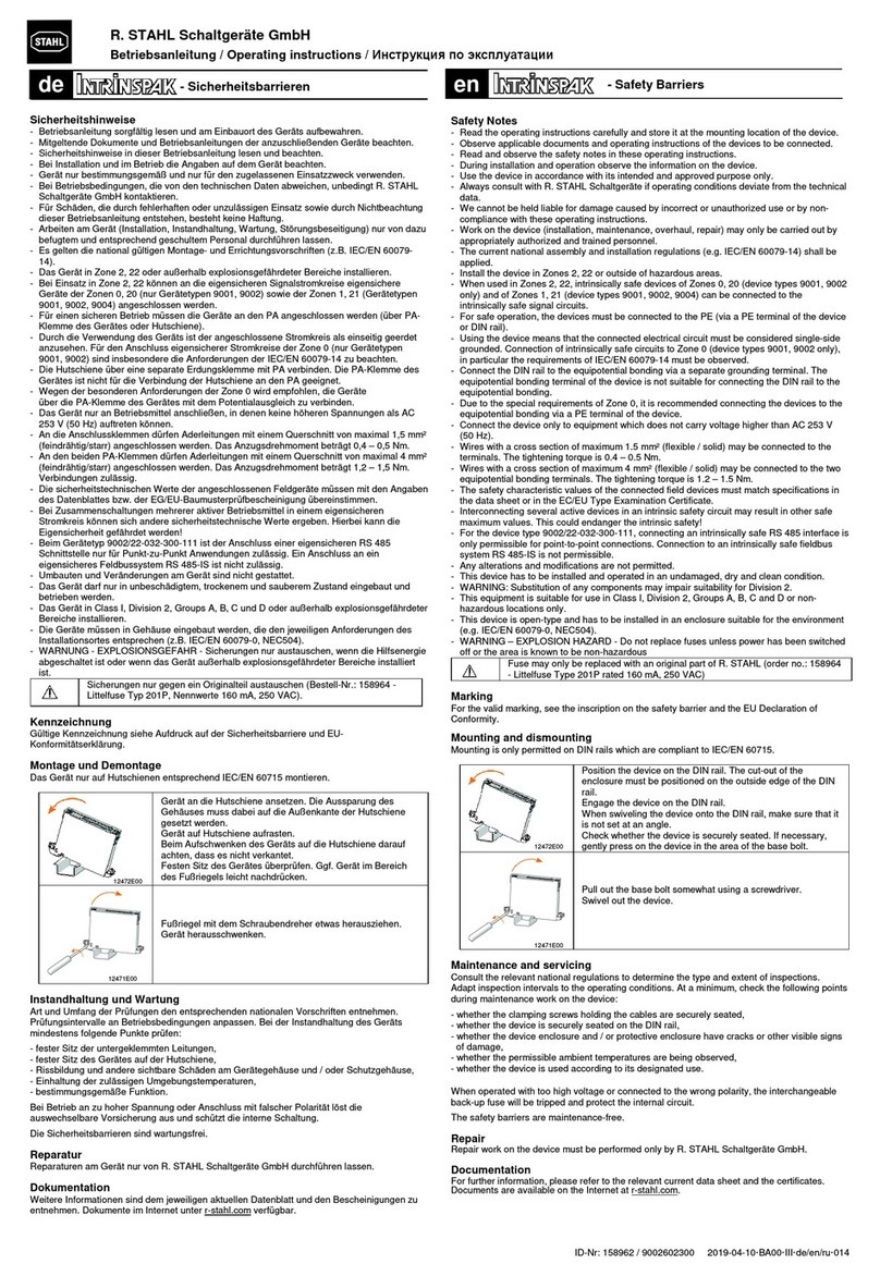
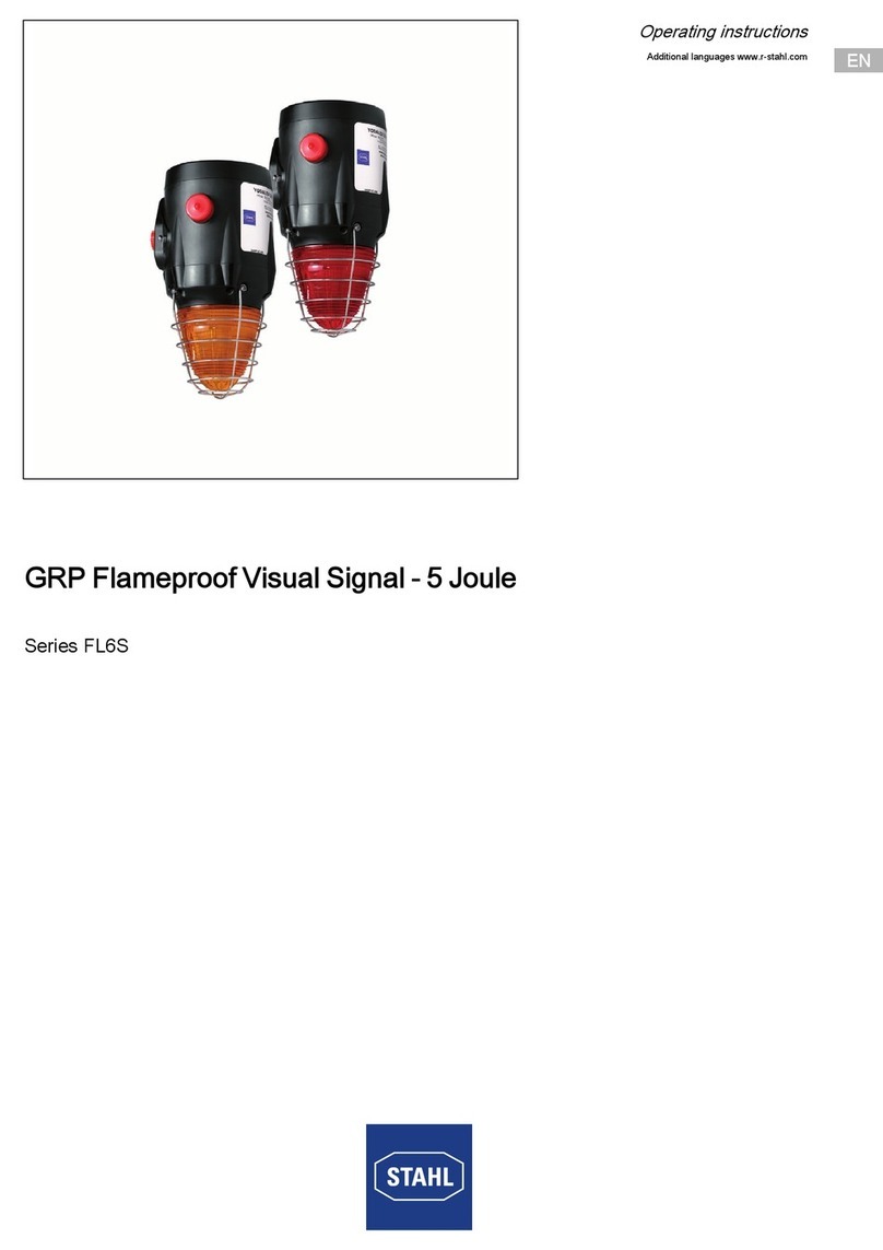
Stahl YL4IS Series User manual

EN
EN
EN
EN
EN
EN
EN
EN
EN
EN
EN
EN
EN
EN
EN
EN
EN
EN
EN
EN
EN
EN
EN
EN
EN
Operating instructions
Additional languages www.stahl-ex.com
EN
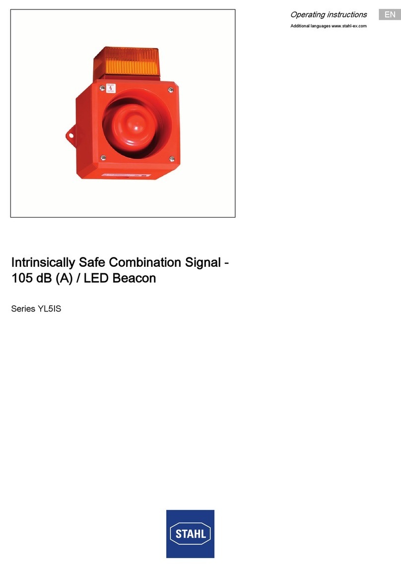
Intrinsically Safe Combination Signal -
100 dB (A) / LED Beacon
Series YL4IS

2Intrinsically Safe Combination Signal -
100 dB (A) / LED Beacon
Series YL4IS
EN
EN
EN
EN
EN
EN
EN
EN
EN
EN
EN
EN
EN
EN
EN
EN
EN
EN
EN
EN
EN
EN
EN
EN
EN
Contents
1 General Information ............................................................................................3
1.1 Manufacturer .......................................................................................................3
1.2 Information regarding the operating instructions .................................................3
1.3 Further documents ..............................................................................................3
1.4 Conformity with standards and regulations .........................................................3
2 Explanation of the symbols .................................................................................3
2.1 Symbols in these operating instructions .............................................................3
2.2 Warning notes .....................................................................................................4
2.3 Symbols on the device ........................................................................................4
3 Safety notes ........................................................................................................5
3.1 Operating instructions storage ............................................................................5
3.2 Safe use ..............................................................................................................5
3.3 Modifications and alterations ..............................................................................5
4 Function and device design ................................................................................6
4.1 Function ..............................................................................................................6
5 Technical data .....................................................................................................6
6 Transport and storage .........................................................................................8
7 Mounting and installation ....................................................................................8
7.1 Dimensions / fastening dimensions ..................................................................10
7.2 Mounting / dismounting, operating position ......................................................11
7.3 Installation .........................................................................................................12
8 Commissioning .................................................................................................19
9 Maintenance and repair ....................................................................................19
9.1 Maintenance .....................................................................................................19
9.2 Repair ...............................................................................................................19
9.3 Returning the device .........................................................................................20
10 Cleaning ............................................................................................................20
11 Disposal ............................................................................................................20
12 Accessories and Spare parts ...........................................................................20

252160 / YL460300010
2016-02-12·BA00·III·en·00
General Information
3
EN
EN
EN
EN
EN
EN
EN
EN
EN
EN
EN
EN
EN
EN
EN
EN
EN
EN
EN
EN
EN
EN
EN
EN
EN
Intrinsically Safe Combination Signal -
100 dB (A) / LED Beacon
Series YL4IS
1 General Information
1.1 Manufacturer
1.2 Information regarding the operating instructions
ID-No.: 252160 / YL460300010
Publication Code: 2016-02-12·BA00·III·en·00
The original instructions are the English edition.
They are legally binding in all legal affairs.
1.3 Further documents
• Data sheet
For documents in further languages, see www.stahl-ex.com.
1.4 Conformity with standards and regulations
See certificates and EC Declaration of Conformity: www.stahl-ex.com.
The device has IECEx approval. See IECEx homepage: http://iecex.iec.ch/
2 Explanation of the symbols
2.1 Symbols in these operating instructions
R. STAHL Schaltgeräte GmbH
Business Unit Lighting & Signalling
Nordstr. 10
99427 Weimar
Germany
R. STAHL Schaltgeräte GmbH
Am Bahnhof 30
74638 Waldenburg
Germany
Phone:
Fax:
Internet:
E-mail:
+49 3643 4324
+49 3643 4221-76
www.stahl-ex.com
Phone:
Fax:
Internet:
E-mail:
+49 7942 943-0
+49 7942 943-4333
www.stahl-ex.com
Symbol Meaning
Tips and recommendations on the use of the device
General danger
Danger due to explosive atmosphere
Danger due to energised parts

Explanation of the symbols
4252160 / YL460300010
2016-02-12·BA00·III·en·00
Intrinsically Safe Combination Signal -
100 dB (A) / LED Beacon
Series YL4IS
EN
EN
EN
EN
EN
EN
EN
EN
EN
EN
EN
EN
EN
EN
EN
EN
EN
EN
EN
EN
EN
EN
EN
EN
EN
2.2 Warning notes
Warnings must be observed under all circumstances, in order to minimize the risk due
to construction and operation. The warning notes have the following structure:
• Signalling word: DANGER, WARNING, CAUTION, NOTICE
• Type and source of danger/damage
• Consequences of danger
• Taking countermeasures to avoid the danger or damage
2.3 Symbols on the device
DANGER
Danger to persons
Non-compliance with the instruction results in severe or fatal injuries
to persons.
WARNING
Danger to persons
Non-compliance with the instruction can result in severe or fatal injuries
to persons.
CAUTION
Danger to persons
Non-compliance with the instruction can result in light injuries to persons.
NOTICE
Avoiding material damage
Non-compliance with the instruction can result in material damage to the device
and / or its environment.
Symbol Significance
05594E00
CE marking according to the current applicable directive.
02198E00
According to its marking, the device is certified for hazardous areas.
15649E00
Input
15648E00
Output
11048E00
Safety instructions that must always be followed: The respective data must
be noted and/or the safety-related instructions contained in the operating
instructions must be followed for devices with this symbol!

252160 / YL460300010
2016-02-12·BA00·III·en·00
Safety notes
5
EN
EN
EN
EN
EN
EN
EN
EN
EN
EN
EN
EN
EN
EN
EN
EN
EN
EN
EN
EN
EN
EN
EN
EN
EN
Intrinsically Safe Combination Signal -
100 dB (A) / LED Beacon
Series YL4IS
3 Safety notes
3.1 Operating instructions storage
• Read the operating instructions carefully.
• Store the operating instructions at the mounting location of the device.
• Observe applicable documents and operating instructions of the devices
to be connected.
3.2 Safe use
• Read and observe the safety notes in these operating instructions!
• Observe characteristic values and rated operating conditions on the rating and data
plates!
• Observe additional information plates on the device!
• Use the device in accordance with its intended and approved purpose only!
• We cannot be held liable for damage caused by incorrect or unauthorized use
or by non-compliance with these operating instructions.
• Before installation and commissioning, make sure that the device is not damaged!
• Work on the device (installation, maintenance, overhaul, repair) may only be carried
out by appropriately authorized and trained personnel.
• During installation and operation, observe the information (characteristic values
and rated operating conditions) on the rating, data and information plates located
on the device.
• Only connect the power supply if certified safety barriers are in place (refer also
to the "Technical data" chapter).
• The safety characteristic values of the connected field devices must match
the specifications of the corresponding device.
• When interconnecting intrinsically safe circuits, the safety-related maximum values
of field devices and corresponding equipment as well as cable parameters must
be observed. This "verification of intrinsic safety" must be performed and
documented according to IEC/EN 60079-14 or IEC/EN 60079-25.
3.3 Modifications and alterations
DANGER
Explosion hazard due to modifications and alterations to the device!
Non-compliance results in severe or fatal injuries.
• Do not modify or alter the device.
No liability or warranty for damage resulting from modifications
and alterations.

Function and device design
6252160 / YL460300010
2016-02-12·BA00·III·en·00
Intrinsically Safe Combination Signal -
100 dB (A) / LED Beacon
Series YL4IS
EN
EN
EN
EN
EN
EN
EN
EN
EN
EN
EN
EN
EN
EN
EN
EN
EN
EN
EN
EN
EN
EN
EN
EN
EN
4 Function and device design
4.1 Function
Application range
In hazardous areas the devices have explosion protection for ATEX/IECEx Zones
0, 1 & 2 for gas and 20, 21 & 22 for dust.
Mode of operation
The YL4IS product series is designed to provide both an audible and visual alarm
which can be used to alert, warn or draw attention to machine malfunction/start up
or any number of safety related issues. The audible and visual signals can be
operated independently or in combination.
5 Technical data
DANGER
Explosion hazard due to improper use!
Non-compliance results in severe or fatal injuries.
• Use the device only in accordance with the operating conditions
described in these operating instructions.
• Use the device only for the intended purpose specified in these
operating instructions.
The YL4IS (Yodalight) features
• A Yodalarm YO4/IS/*/T* audible alarm, certified according to
BAS02ATEX1190X (without certification label)
• An IS signal beacon, certified according to Baseefa05ATEX0075/2X
(without certification label)
Both alarm components are installed in a three-compartment enclosure,
certified according to Baseefa08ATEX0194X. Connections are made
to the terminal blocks of the individual units.
Explosion Protection
Europe (ATEX)
Gas and dust Baseefa08ATEX0194X
E II 1 G Ex ia IIC T4 Ga
E II 1 D Ex ia IIIC T190°C Da
Certifications and certificates
Certificates ATEX, India (PESO)
Technical Data
Electrical data
Rated operational
voltage
16.2 ... 26.4 V

252160 / YL460300010
2016-02-12·BA00·III·en·00
Technical data
7
EN
EN
EN
EN
EN
EN
EN
EN
EN
EN
EN
EN
EN
EN
EN
EN
EN
EN
EN
EN
EN
EN
EN
EN
EN
Intrinsically Safe Combination Signal -
100 dB (A) / LED Beacon
Series YL4IS
Current consumption
*) combined supply
Certified input
parameters
Independent
wiring
Combined supply
Line monitoring yes
Acoustic data
Volume max. 100 dB(A) / 1 m
Volume control 15 dB (A) adjustment
(T4 Models only)
Sound stages 2
Sound selection via DIL-switch
Luminous characteristics
Light source 8 array LED
Flash rate 1/s
Lens colour amber, red, green, opal, blue, clear
Ambient conditions
Operating
temperature range
-25 to +40°C
Storage temperature -40 to +70°C
Max. relative
humidity
95 % at 40 °C
Technical Data
Power supply Certified barrier /
isolator parameters
Current consumption
tone 1*)
Sound output
dB (A) / 1 m
24 V DC 28 V / 300 Ω 24 mA 99 dB (A) / 1 m
18 V DC 28 V / 300 Ω 33 mA 94 dB (A) / 1 m
beacon sounder
Ui= 30 V 30 V
Ii= 200 mA 133 mA
Pi= 0.7 W 0.7 W
Ci=0 0
Li=0 0
Ui=30 V
Ii=133 mA
Pi= 0.7 W
Ci=0
Li=0

Transport and storage
8252160 / YL460300010
2016-02-12·BA00·III·en·00
Intrinsically Safe Combination Signal -
100 dB (A) / LED Beacon
Series YL4IS
EN
EN
EN
EN
EN
EN
EN
EN
EN
EN
EN
EN
EN
EN
EN
EN
EN
EN
EN
EN
EN
EN
EN
EN
EN
For further technical data, see www.stahl-ex.com.
6 Transport and storage
• Transport and store the device only in the original packaging.
• Store the device in a dry place (no condensation) and vibration-free.
• Do not drop the device.
7 Mounting and installation
The device is approved for use in gas explosion hazardous areas of Zones 1 and 2
and dust explosion hazardous area of Zones 21 and 22 and in safe areas.
Mechanical data
Cable entries 1 x M20
Material
Enclosure ABS, flame retardant
Lens polycarbonate, flame retardant
Assembly parts stainless steel fixings
Labels polyester foil, adhesive
Degree of protection IP55 acc. to IEC 60529
Mounting / Installation
Mounting Should be mounted to a reasonably flat wall or bulkhead of suitable material
using the lugs projecting from the side of the enclosure. The minimum
recommended length of fixing screws is 25 mm. To maintain the integrity
of the weather seal the cable entry must be fitted using a suitable sealed gland.
Connection Independent wiring or combined supply
2.5 mm2 terminals
DANGER
Explosion hazard due to installation without approved field enclosure!
Non-compliance results in severe or fatal injuries!
• When used in Zone 1, the device must be installed into an enclosure
that complies with the requirements of IEC/EN 60079-11.
• When used in Zone 2, the device must be installed into an enclosure
that complies with the requirements of IEC/EN 60079-15.
• When used in Zones 21 and 22, the device must be installed into
an enclosure that complies with the requirements of IEC/EN 60079-31.
Technical Data

252160 / YL460300010
2016-02-12·BA00·III·en·00
Mounting and installation
9
EN
EN
EN
EN
EN
EN
EN
EN
EN
EN
EN
EN
EN
EN
EN
EN
EN
EN
EN
EN
EN
EN
EN
EN
EN
Intrinsically Safe Combination Signal -
100 dB (A) / LED Beacon
Series YL4IS
17769E00
Example of a standard installation using an intrinsically safe field device. Product series
9001 is a safety barrier manufactured by STAHL. Certified components from other
manufactures are acceptable.
DANGER
Explosion hazard due to incorrect installation of the device!
Non-compliance results in severe or fatal injuries.
• Carry out installation strictly according to the instructions and national
safety and accident prevention regulations to maintain the explosion
protection.
• Select and install the electrical device so that explosion protection
is not affected due to external influences, i.e. pressure conditions,
chemical, mechanical, thermal and electric impact such as vibration,
humidity
and corrosion (see IEC/EN 60079-14).
• The device must only be installed by trained qualified personnel
who is familiar with the relevant standards.
DANGER
Explosion hazard due to improper mains power connection!
Non-compliance results in severe or fatal injuries.
• Under no circumstances is the device to be supplied using a regular
power supply. It is only to be connected using certified barriers/isolators
(see "Technical data")

Mounting and installation
10 252160 / YL460300010
2016-02-12·BA00·III·en·00
Intrinsically Safe Combination Signal -
100 dB (A) / LED Beacon
Series YL4IS
EN
EN
EN
EN
EN
EN
EN
EN
EN
EN
EN
EN
EN
EN
EN
EN
EN
EN
EN
EN
EN
EN
EN
EN
EN
7.1 Dimensions / fastening dimensions
Dimensional Drawings (All Dimensions in mm [inches]) – Subject to Alterations
14000E00
16547E00
91,50 [3,60]
91,50 [3,60]
81,50 [3,21]
2 x M20
A
1 x M20
A
2 x M20
A
91,50 [3,60]
91,50 [3,60]
274 10 81,50 [ , ]
82 25,50 [3, ]
81 21,50 [3, ]
30,20
5 [0,20]
60,40 [2,38]
45°
45x M
B
[1,19]
30,20
60,40 [2,38]
[1,19]
[ø 2 0],0
ø 50,80
1 x M20
A
45x M
C
A = knockout hole
B = drill hole
C = knockout hole

252160 / YL460300010
2016-02-12·BA00·III·en·00
Mounting and installation
11
EN
EN
EN
EN
EN
EN
EN
EN
EN
EN
EN
EN
EN
EN
EN
EN
EN
EN
EN
EN
EN
EN
EN
EN
EN
Intrinsically Safe Combination Signal -
100 dB (A) / LED Beacon
Series YL4IS
7.2 Mounting / dismounting, operating position
7.2.1 Assembly
17771E00
• Open the device.
• Drill holes for mounting the back of the enclosure to a flat surface.
• Install the seal for the IP protective enclosure that was included in delivery.
• Mount the device to the surface, as depicted.
• Close the enclosure.

Mounting and installation
12 252160 / YL460300010
2016-02-12·BA00·III·en·00
Intrinsically Safe Combination Signal -
100 dB (A) / LED Beacon
Series YL4IS
EN
EN
EN
EN
EN
EN
EN
EN
EN
EN
EN
EN
EN
EN
EN
EN
EN
EN
EN
EN
EN
EN
EN
EN
EN
7.3 Installation
7.3.1 Key components
Exploded diagram for the model used with YL4 6 001 001 0 (YL4IS D5)
Prewiring
The sound pressure transducer (F) is fixed to the back side of the sounder front cover (4).
It is prewired to the sounder PCB (3).
17773E00
1 Lower enclosure part
2 Through hole
3 Sounder PCB
4 Sounder front cover
5 Beacon PCB
6 Sounder PCB cover
7 Lens cover
17774E00
F Sounder pressure transducer
Do not separate the cables during installation.

252160 / YL460300010
2016-02-12·BA00·III·en·00
Mounting and installation
13
EN
EN
EN
EN
EN
EN
EN
EN
EN
EN
EN
EN
EN
EN
EN
EN
EN
EN
EN
EN
EN
EN
EN
EN
EN
Intrinsically Safe Combination Signal -
100 dB (A) / LED Beacon
Series YL4IS
7.3.2 Electrical Connection
PCB
• Remove the sounder PCB cover.
• Remove the lens cover.
• Connect the leads according to the circuit diagram.
• Replace the PCB and lens covers.
7.3.3 Circuit diagrams
Single stage alarm
• Connect the leads according to the circuit diagram.
• Supply the active device with power.
The device contains two printed circuit boards. The PCBs can be wired independently
or can be connected together by looping in and out of the sounder PCB.
Independent wiring
• A dual-channel safety barrier or double intrinsically safe connection is required
Sounder PCB
Beacon PCB
DANGER
Explosion hazard due to selecting the wrong cables!
Non-compliance results in severe or fatal injuries.
• If using separate safety barriers for the sounder and beacon,
observe the cable specifications stated on the selected Zener barrier
or on the isolator certificate.
17775E00
A 0v
B +v
17776E00
A 0v
B +v

Mounting and installation
14 252160 / YL460300010
2016-02-12·BA00·III·en·00
Intrinsically Safe Combination Signal -
100 dB (A) / LED Beacon
Series YL4IS
EN
EN
EN
EN
EN
EN
EN
EN
EN
EN
EN
EN
EN
EN
EN
EN
EN
EN
EN
EN
EN
EN
EN
EN
EN
Loop in/loop out wiring combination device
• A single-channel safety barrier or single intrinsically safe connection is required
• Wires C and D not included in delivery
Two stage alarm
Tone selection of the sound stages
17777E00
A 0v
B +v
C 0v
D +v
The device has a first and second sound stage.
First sound stage
• Users can select a tone frequency from 32 different variations using
the DIL switch (see diagrams above). Each tone is described in the tone
table.
Second sound stage
• Each first sound stage has a pre-programmed second stage which
is listed in the tone table.
• Users are able to switch between the first and second sound stages
by wiring the unit in one of two ways.

252160 / YL460300010
2016-02-12·BA00·III·en·00
Mounting and installation
15
EN
EN
EN
EN
EN
EN
EN
EN
EN
EN
EN
EN
EN
EN
EN
EN
EN
EN
EN
EN
EN
EN
EN
EN
EN
Intrinsically Safe Combination Signal -
100 dB (A) / LED Beacon
Series YL4IS
7.3.4 Sound tone switching
Sound tone switching by using a third cable
Connect the leads according to the figure.
• Supply "B" with power to activate the first sound tone frequency.
• Supply "B"and "C" with power according to the circuit diagram for the second tone
frequency.
• A dual-channel barrier or double intrinsically safe connection is required.
Tone switching using reverse polarity
• Connect the leads according to the figure.
• Supply with power to activate the first sound tone frequency.
• Reverse the polarity to activate the second sound tone frequency. The sounder PCB
and beacon PCB must be wired independently if using reverse polarity to switch
between sound tone frequencies.
17778E00
A 0v
B +v
C +v
Loop in/loop out wiring to the beacon is possible with this configuration.
17779E00
D 0v
E +v
17779E00
D +v
E 0v

Mounting and installation
16 252160 / YL460300010
2016-02-12·BA00·III·en·00
Intrinsically Safe Combination Signal -
100 dB (A) / LED Beacon
Series YL4IS
EN
EN
EN
EN
EN
EN
EN
EN
EN
EN
EN
EN
EN
EN
EN
EN
EN
EN
EN
EN
EN
EN
EN
EN
EN
7.3.5 Line monitoring
Standard termination with monitoring resistor fitted.
7.3.6 Sound tone selection (YL4IS D16)
17784E00
• Arrange the settings of the DIP switch using a suitable tool:
• DIP switch "up" corresponds to "1"
• DIP switch "down" corresponds to "0"
Refer to the following tone table for the tone selection.
If line monitoring is required, this can be achieved by using an end-of-line
resistor. For this purpose, use a wire-wound or metal layer resistor with
a resistance value of at least 750 Ohm and a rated power of at least 2 W
or at least 4700 Ohm and a rated power of at least 0.4 W!
The line monitoring facility allows the integrity of the line to the sounder
to be monitored through the barrier to the control system fault detection
and indication circuits. Two sounders of the same type can be connected
in parallel. The resistor can be fitted as per the diagram below.
Line monitoring is optional. The system designer should inform users if this
is necessary or not.
17782E00
R1 Resistor – Value to be defined
by system designer
A 0v
B +v

252160 / YL460300010
2016-02-12·BA00·III·en·00
Mounting and installation
17
EN
EN
EN
EN
EN
EN
EN
EN
EN
EN
EN
EN
EN
EN
EN
EN
EN
EN
EN
EN
EN
EN
EN
EN
EN
Intrinsically Safe Combination Signal -
100 dB (A) / LED Beacon
Series YL4IS
Tone table
First
sound
level
signal
Tone
description
Frequency
[Hz]
Repetition
frequency
[sec]
Second
sound
level signal.
Tone
changes
1 2 3 4 5
Output
[db(A)]
Input
current
[mA]
1Two alternating
tones
800-1000 0.5 31 1 1 1 1 100 26
2Two alternating
tones
2500-3100 0.5 40 1 1 1 1 102 34
3Two alternating
tones
800-1000 0.25 71 0 1 1 1 100 25
4Two alternating
tones
2500-3100 0.25 80 0 1 1 1 103 34
5Two alternating
tones
440-554 0.4/0.1 14 1 1 0 1 1 98 24
6Two alternating
tones
430-470 1.0 14 0 1 0 1 1 98 24
7Two alternating
tones
800-1000 0.13 12 1 0 0 1 1 100 25
8Two alternating
tones
2500-3200 0.07 13 0 0 0 1 1 102 34
9Two alternating
tones
440-554 2.0 10 1 1 1 0 1 98 24
10 Continuous
tone
700 – 1 0 1 1 0 1 99 25
11 Continuous
tone
1000 –31 1 0 1 0 1 98 24
12 Continuous
tone
1000 – 7 0 0 1 0 1 101 25
13 Continuous
tone
2300 – 2 1 1 0 0 1 101 30
14 Continuous
tone
440 – 9 0 1 0 0 1 98 24
15 Interrupted
tone
1000 2.0 31 1 0 0 0 1 97 24
16 Interrupted
tone
420 1.25 30 0 0 0 0 1 97 24
17 Interrupted
tone
1000 0.5 11 1 1 1 0 98 24
18 Interrupted
tone
2500 0.25 40 1 1 1 0 101 30
19 Interrupted
tone
2500 0.5 21 0 1 1 0 101 29
20 Interrupted
tone
700 6/12 10 0 0 1 1 0 100 24
21 Interrupted
tone
1000 1.0 32 1 1 0 1 0 99 24
22 Interrupted
tone
700 4.0 10 0 1 0 1 0 99 24

Mounting and installation
18 252160 / YL460300010
2016-02-12·BA00·III·en·00
Intrinsically Safe Combination Signal -
100 dB (A) / LED Beacon
Series YL4IS
EN
EN
EN
EN
EN
EN
EN
EN
EN
EN
EN
EN
EN
EN
EN
EN
EN
EN
EN
EN
EN
EN
EN
EN
EN
7.3.7 Volume control
17785E00
• Upon request, the volume can be reduced by turning the potentiometer anticlockwise.
7.3.8 Earth connection (YL4IS D15)
17783E00
23 Interrupted
tone
700 0.25 10 1 0 0 1 0 97 23
24 Interrupted
tone
720 0.7/0.3 10 0 0 0 1 0 99 24
25 Interrupted,
fast, rising
volume
1400 0.25 26 1 1 1 0 0 101 28
26 Fast siren 250-1200 0.085 11 0 1 1 0 0 99 24
27 Rising, falling
constantly
1000 10/40/10 17 1 0 1 0 0 100 25
28 ISO 8201
Evacuation
800-1000 As
standard
11 0 0 1 0 0 97 23
29 Fast wailing
noise
500-1000 0.15 32 1 1 0 0 0 99 25
30 Slow wailing
noise
500-1200 4.5 12 0 1 0 0 0 100 25
31 Reverse
sweep
1200-500 1.0 11 1 0 0 0 0 98 24
32 Siren 500-1200 3.0 26 0 0 0 0 0 98 24
The product is supplied with the volume set to full.

252160 / YL460300010
2016-02-12·BA00·III·en·00
Commissioning
19
EN
EN
EN
EN
EN
EN
EN
EN
EN
EN
EN
EN
EN
EN
EN
EN
EN
EN
EN
EN
EN
EN
EN
EN
EN
Intrinsically Safe Combination Signal -
100 dB (A) / LED Beacon
Series YL4IS
8 Commissioning
Before commissioning, ensure the following:
• Check the mounting and installation.
• Enclosure must not be damaged.
• If necessary, remove foreign bodies.
• If necessary, clean the connection chamber.
• Check if the conductors have been inserted correctly.
• Check if all screws and nuts have been tightened firmly.
• Check if all conductors have been clamped firmly.
• Check if all prescribed tightening torques have been observed.
• Check whether the bayonet lock is tightened firmly.
• Make sure that the plug pin surface is not damaged.
• Use only in completely mounted state.
9 Maintenance and repair
9.1 Maintenance
9.2 Repair
DANGER
Explosion hazard due to incorrect installation!
Non-compliance results in severe or fatal injuries.
• Check the device for proper installation before commissioning.
• Comply with national regulations.
CAUTION
Risk of electric shock or malfunction of the device due to unauthorized work!
Non-compliance can result in light injuries!
• Before carrying out work on the device, switch off voltage supply.
• Work performed on the device must only be carried out by authorized
and appropriately trained qualified electricians.
Observe the relevant national regulations in the country of use.
DANGER
Explosion hazard due to improper repair!
Non-compliance results in severe or fatal injuries.
• Repair work on the devices must be performed only by
R. STAHL Schaltgeräte GmbH.

Cleaning
20 252160 / YL460300010
2016-02-12·BA00·III·en·00
Intrinsically Safe Combination Signal -
100 dB (A) / LED Beacon
Series YL4IS
EN
EN
EN
EN
EN
EN
EN
EN
EN
EN
EN
EN
EN
EN
EN
EN
EN
EN
EN
EN
EN
EN
EN
EN
EN
9.3 Returning the device
Use the "Service form" to return the device if repair or service is required.
On the internet site "www.stahl-ex.com" under "Downloads > Customer service":
• Download the service form.
• Fill out the service form.
• Send the device along with the service form in the original packaging to
R. STAHL Schaltgeräte GmbH.
10 Cleaning
• To avoid electrostatic charging, the devices located in potentially explosive areas may
only be cleaned using a damp cloth.
• When cleaning with a damp cloth, use water or mild, non-abrasive, non-scratching
cleaning agents.
• Do not use aggressive detergents or solvents.
11 Disposal
• Observe national and local regulations and statutory regulation regarding disposal.
• Separate materials when sending it for recycling.
• Ensure environmentally friendly disposal of all components according to the statutory
regulations.
12 Accessories and Spare parts
NOTE
Malfunction or damage to the device due to the use of non-original components.
Non-compliance can result in material damage.
• Use only original accessories and spare parts from R. STAHL Schaltgeräte GmbH.
For accessories and spare parts, see data sheet on our homepage
www.stahl-ex.com.
Table of contents
Other Stahl Security Sensor manuals