manuals.online logo
Brands
  1. Home
  2. •
  3. Brands
  4. •
  5. Stahl
  6. •
  7. Security System
  8. •
  9. Stahl YA50 Series User manual

Stahl YA50 Series User manual

YA50
266200 / YA50 6 030 003 0
2018-03-07·BA00·III·de en·00
Akustisches Signal 110 dB (A)
Audible Signal 110 dB (A) 1
Akustisches Signal
Industrieausführung
Industrial Audible Signal
110 dB (A)
Type YA50
Allgemeine Angaben / General Information
Hersteller / Manufacturer
R. STAHL Schaltgeräte GmbH
Am Bahnhof 30
74683 Waldenburg
Germany/Deutschland
Produktion / Manufacturing Location
R. STAHL (P) Limited
Plot No. 5 Malrosapuram Main Road, Sengundram Industrial Area,
Malrosapuram Post, Singaperumal Koil,
Kanchipuram District, Tamil Nadu, India, PIN - 603 204
Angaben zur Betriebsanleitung
ID-Nr.: 266200 / YA50 6 030 003 0
Publikationsnummer: 2018-03-07·BA00·III·de en·00
Die Originalbetriebsanleitung ist die englische Ausgabe. Diese ist
rechtsverbindlich in allen juristischen Angelegenheiten
Weitere Informationen siehe Datenblatt oder www.r-stahl.com
Information regarding the manual
ID-No.: 266200 / YA50 6 030 003 0
Publication Code: 2018-03-07·BA00·III·de en·00
The original instructions are the English edition. They are legally
binding in all legal affairs.
Further Information see Datasheet or www.r-stahl.com
Sicherheitshinweise
Sicherheitshinweise in dieser Betriebsanleitung lesen und
beachten!
Kennwerte und Bemessungsbetriebsbedingungen der Typ- und
Datenschilder beachten!
Zusätzliche Hinweisschilder auf dem Gerät beachten!
Gerät nur bestimmungsgemäß und nur für den zugelassenen
Einsatzzweck verwenden!
Für Schäden, die durch fehlerhaften oder unzulässigen Einsatz
sowie durch Nichtbeachtung dieser Betriebsanleitung entstehen,
besteht keine Haftung.
Vor Installation und Inbetriebnahme sicherstellen, dass das Gerät
unbeschädigt ist!
Arbeiten am Gerät (Installation, Instandhaltung, Wartung,
Störungsbeseitigung) nur von dazu befugtem und entsprechend
geschultem Personal durchführen lassen!
Safety Notes
Read and observe the safety notes in these operating instructions!
Observe characteristic values and rated operating conditions on
the rating and data plates!
Observe additional information plates on the device!
Use the device in accordance with its intended and approved
purpose only!
We cannot be held liable for damage caused by incorrect or
unauthorized use or by non-compliance with these operating
instructions.
Before installation and commissioning, make sure that the device is
not damaged!
Work on the device (installation, maintenance, overhaul, repair)
may only be carried out by appropriately authorized and trained
personnel.
Erläuterung der Symbole
Explanation of the symbols
Hinweis
Notice
Tipps und Empfehlungen zum Gebrauch des
Geräts
Tips and recommendations on the use of the
device
Gefahr
Danger
Gefahr durch spannungsführende Teile
Danger due to energised parts
YA50
266200 / YA50 6 030 003 0
2018-03-07·BA00·III·de en·00
Akustisches Signal 110 dB (A)
Audible Signal 110 dB (A) 2
Aufbau / Device design
1 2 3 4 5
Montage:
Das YA50 Signalgerät ist zur Montage an einer Wand oder ähnlich
geeigneter Konstruktion vorgesehen. Befestigungspunkte sind die
seitlichen Laschen am Gehäuse. Die Befestigungslöcher haben
einen Durchmesser von 8 mm und einen Abstand von 153 mm.
Die Befestigungsschrauben sollten eine Länge von 25 mm haben.
Im Auslieferungszustand ist das Gehäuseunterteil (1) nicht mit dem
Gerät verschraubt.
Die Stromversorgung wird an die Klemmen wie unten beschrieben
angeschlossen.
Nachdem das Gehäuseoberteil (3) wie oben dargestellt mit den
Befestigungsschrauben auf das Gehäuseunterteil geschraubt
wurde, ist die Montage abgeschlossen.
Zum Schutz gegen das Eindringen von Staub und Feuchtigkeit ist
eine geeignete Leitungseinführung mit Dichtung zu verwenden.
Mounting:
The YA50 series alarm units are mounted to a wall or bulkhead of
suitable material using the lugs projecting from the side of the case.
The lugs are bored 8 mm clearance on 153 mm centres. The
recommended length of fixing screws is 25mm.
All units are supplied separate from the back box (1).
Connect the power supply to the appropriate terminals as shown
below. The installation is completed by fitting the cover
assembly (3) onto the back box by means of the fixing screws (5)
as shown above.
To maintain the integrity of the weather seal, the cable entry must
be fitted using a suitable sealed gland.
Elektrischer Anschluss
24 V / 48 V DC Version
Electrical connection
24 V AC / 115 V / 230 V AC Version
Draht / wire: 2.5mm2max (AWG 14 .. AWG 20).
1. Gehäuseunterteil / back box
2. Scheibe / washer
3. Gehäuseoberteil / cover assembly
4. Scheibe / washer
5.
Befestigungsschrauben
/ fixing screws
YA50
266200 / YA50 6 030 003 0
2018-03-07·BA00·III·de en·00
Akustisches Signal 110 dB (A)
Audible Signal 110 dB (A) 3
Signalauswahl:
Vor Beginn der Arbeiten die Versorgung spannungsfrei schalten.
Alle DC- und AC-Geräte haben auswählbare Alarmsignale (siehe
untenstehende Tabelle) und können über einen 5-fach DIP-
Schalter, SW1, eingestellt werden. Das Signal der zweiten Stufe
kann bei DC Geräten über SW2 unabhängig gewählt werden.
Das Signal der zweiten Stufe ertönt bei Versorgung eines dritten
Leiters. Bei DC Geräten an der Klemme TB1-3, wobei der
Anschluss an TB1-1&2 erhalten bleibt. Bei AC Geräten an der
Klemme TB3, wobei der Anschluss an TB1 und TB2 erhalten
bleibt. Siehe Abbildung oben.
Alternativ können die erste und zweite Signalstufe durch eine
Spannungsumkehr an TB1-3&4 erzeugt werden
(Nur bei DC-Geräten)
Sound selection:
Ensure the supply is OFF before proceeding. All DC and AC units
have selectable alarm sounds (see table below for details) and are
selectable by means of a 5 way DIL switch SW1 for AC units and
SW1 & SW2 for DC units. Independent second stage sound is
available for DC units by using SW2.
A second stage sound is made available upon the application of a
third wire: DC units to be connected to terminal TB1-3, while still
connected to terminal TB1-1&2. AC units to be connected to
terminal TB3, while still connected to terminal TB1 and TB2.
See illustration above.
Alternatively 1st and 2nd stage sound signals can be generated by
supply reversal to TB1-3&4 (applicable for DC units only).
Signaltabelle (Auswahl, vollständige Tabelle siehe Website)
Sound table (Selection, complete list see website)
1. Signalstufe
1st Stage Sound
Frequenz [Hz]
Frequency
Wdh
Rept.
2. / 2nd
Stage
DIL / DIP
1 2 3 4 5
Anwendung
Application
#
1
Zweitonsignal / Alternate two-tone
800-1000
0.5
3
1 1 1 1 1
Feueralarm / Fire Alarm
#
5
Zweitonsignal / Alternate two-tone
440-554
0.4/0.1
14
1 1 0 1 1
AFNOR, Frankreich / France
#
11
Dauerton / Continuous note
1000
-
31
1 0 1 0 1
#
15
Unterbrochener Ton / Interrupted tone
1000
2.0
31
1 0 0 0 1
#
16
Unterbrochener Ton / Interrupted tone
420
1.25
30
0 0 0 0 1
AS2220, Australien / Australia
#
28
ISO 8201 Evakuierung / Evacuation
800-1000
Standard
11
0 0 1 0 0
Evakuierungsalarm
Evacuation alarm
#
30
Langsamer Whoop / Slow whoop
500-1200
4.5
12
0 1 0 0 0
Evakuierung, Niederlande
Evacuation, Netherlands
#
31
Rückwärtssweep / Reverse sweep
1200-500
1
11
1 0 0 0 0
Evakuierung, Deutschland
Evacuation, Germany
32
Sirene / Siren
500-1200
3.0
26
0 0 0 0 0
Schaltereinstellungen: ON=1 und OFF=0 / switch settings: ON=1 and OFF=0
#: Ton nach EN 54-3 geprüft / Ton tested according to EN 54-3
Technische Daten / Technical data
Umgebungsbedingungen / Ambient conditions
Betriebstemperatur /
Operating temperature
-25 °C … +55 °C (Standard)
-35 °C … +66 °C (UL)
-25 °C … +40 °C (VdS)
Lagertemperatur / Storage temperature
-40 °C … +70 °C
Mechanische Daten / Mechanical data
IP-Schutz
IP-protection
IP54 (Standard)
IP65 (WR Ausführung / WR version)
Elektrische Daten / Electrical data
Schalldruck / Volume
Max 110 dB (A)
Tonstufen /
Sound stages
2
Ausführung
Version
Spannung
Rated voltage
Stromaufnahme
Current consumption
YA50/D
24 V DC ± 10 %
39 mA
YA50/I
24 VAC ± 10 %
90 mA
YA50/L
115 VAC ± 10 %
23 mA
YA50/N
230 V AC ± 10 %
15 mA
YA50
266200 / YA50 6 030 003 0
2018-03-07·BA00·III·de en·00
Akustisches Signal 110 dB (A)
Audible Signal 110 dB (A) 4
Zertifikate, falls anwendbar / Certificates, where applicable
VdS
G28702
Kitemark
KM91259
MED
BSI/MED/A.1/3.53/590299
CPR
0086-CPR-96705
UL
E161819 (General Signaling Equipment)
11
Hinweis
Notice
Die Declaration of Performance (DoP) sowie die
MED Declaration of Conformity (DoC) stehen zum
Download unter www.r-stahl.com bereit.
The Declaration of Performance (DoP) and the
MED Declaration of Conformity (DoC) are available
for download at www.r-stahl.com
Montagezeichnung / Mounting drawing
Polardiagramm / Polar Diagram Tone 11
Alle Maße in mm - Änderungen vorbehalten
All dimensions in mm - Subject to alterations
Weitere Töne gemäß EN 54-3 siehe Website
See website for all other EN 54-3 approved tones
Änderungen an technischen Daten, Abmessungen, Gewichten, Konstruktion und Produkten bleiben vorbehalten.
Die Abbildungen sind unverbindlich.
We reserve the right to make alterations to the technical data, dimensions, weights, designs and products available without notice.
The illustrations cannot be considered binding.

This manual suits for next models

1

Other Stahl Security System manuals

Stahl ConSig 8040 Series User manual

Stahl

Stahl ConSig 8040 Series User manual

Stahl YA11 User manual

Stahl

Stahl YA11 User manual

Stahl YL6S Series User manual

Stahl

Stahl YL6S Series User manual

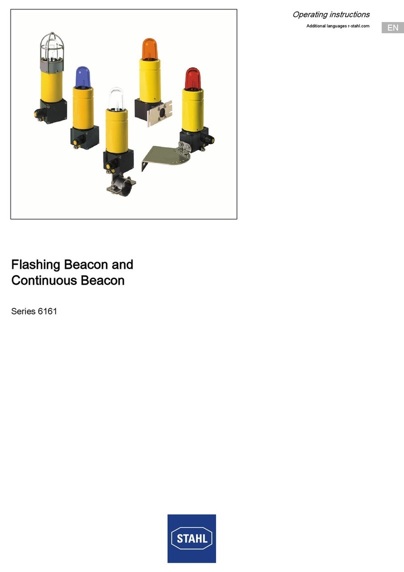
Stahl 6161 Series User manual

Stahl

Stahl 6161 Series User manual

Stahl YL60 Series User manual

Stahl

Stahl YL60 Series User manual

Stahl Clifford & Snell YL40 User manual

Stahl

Stahl Clifford & Snell YL40 User manual

Stahl YL6S Series User manual

Stahl

Stahl YL6S Series User manual

Stahl 8491/2 Series User manual

Stahl

Stahl 8491/2 Series User manual

Stahl YA60 Series User manual

Stahl

Stahl YA60 Series User manual

Stahl YL6 Series User manual

Stahl

Stahl YL6 Series User manual

Stahl Clifford & Snell Y05 User manual

Stahl

Stahl Clifford & Snell Y05 User manual

Stahl YA60 Series User manual

Stahl

Stahl YA60 Series User manual

Stahl FX15 Series User manual

Stahl

Stahl FX15 Series User manual

Stahl YA60 Series User manual

Stahl

Stahl YA60 Series User manual

Stahl Clifford & Snell YL50 User manual

Stahl

Stahl Clifford & Snell YL50 User manual

Popular Security System manuals by other brands

Amroad ID5101 installation manual

Amroad

Amroad ID5101 installation manual

Tracon Electric VF100 Series user manual

Tracon Electric

Tracon Electric VF100 Series user manual

GKD SENSORZONE installation manual

GKD

GKD SENSORZONE installation manual

RHINO 832 Installation & operation manual

RHINO

RHINO 832 Installation & operation manual

Axis F41 installation guide

Axis

Axis F41 installation guide

ELRO Pro Alarm System AP5500 quick start guide

ELRO

ELRO Pro Alarm System AP5500 quick start guide

Trend Micro TippingPoint TPS 440T manual

Trend Micro

Trend Micro TippingPoint TPS 440T manual

Verex Monitor ISM user guide

Verex

Verex Monitor ISM user guide

SEBSON HD GS412 manual

SEBSON

SEBSON HD GS412 manual

IQcare NOBU GO Installation operation & maintenance

IQcare

IQcare NOBU GO Installation operation & maintenance

Alphatron ALPHA BNWAS Installation & operation manual

Alphatron

Alphatron ALPHA BNWAS Installation & operation manual

HomeMatic HM-Sec-Sir-WM Installation and operating manual

HomeMatic

HomeMatic HM-Sec-Sir-WM Installation and operating manual

YOKOGAWA VJRK user manual

YOKOGAWA

YOKOGAWA VJRK user manual

HOME8 V63020US quick start guide

HOME8

HOME8 V63020US quick start guide

Tork GA 21 user manual

Tork

Tork GA 21 user manual

Sprue FireAngel LPG-9B-INT manual

Sprue

Sprue FireAngel LPG-9B-INT manual

Fire Burglary Instruments XL-3 owner's manual

Fire Burglary Instruments

Fire Burglary Instruments XL-3 owner's manual

Daiichi Electronics FINE Series instruction manual

Daiichi Electronics

Daiichi Electronics FINE Series instruction manual

manuals.online logo
manuals.online logoBrands
  • About & Mission
  • Contact us
  • Privacy Policy
  • Terms and Conditions

Copyright 2025 Manuals.Online. All Rights Reserved.