Stahlwille Standard MANOSKOP 721/5 User manual

EN
28
STAHLWILLE
Standard MANOSKOP®
721
Service MANOSKOP®
730
Technical description
All models
MANOSKOP®721, 730 are adjustable
torque wrenches with a cut-out, tactile
and audible cut-out signals.
These torque wrenches have a safety
cut-out mechanism.
The wrench is set to cut-out at a
certain torque level by setting the
required value on the force-free sliding
scale.
The setting slide has an automatic
setting fail-safe mechanism.
The measuring element is a flexible
rod. The flexible rod is not
pretensioned so it is only under tension
from the start to the end of the actual
tightening operation until the wrench
cuts out.
List of contents
Technical description ..................28
Safety instructions ......................32
Operation ....................................35
Maintenance ...............................44
Cleaning .....................................49
Accessories ................................50
Disposal ......................................50

29
As soon as the torque wrench is
released, it is ready for the next job.
These wrenches will only tighten in
one direction. To use the wrench for
loosening, turn it over. Exception: The
MANOSKOP®721/5, 721/15 and
721/20 cannot be used for counter
clockwise tightening.
If necessary, these torque wrenches
can be readjusted without dismantling.
Maximum permissible deviation of the set
value from the absolute value at cut-out is
4%. MANOSKOP®721 and 730 comply
with DIN EN ISO 6789, Type II, Class A.
Every MANOSKOP®has a unique serial
number and is supplied with a works
calibration certificate.
MANOSKOP®721/5, 721/15
and 721/20 ...
... have a permanent, switchable ratchet
with a permanent square drive (sizes are
shown in the Technical Specifications on
page 30). Controlled counter clockwise
tightening is not possible.
Standard MANOSKOP®
721/30 ...
... has a permanent, switchable ratchet
with a push-through 12.5 (1/2") square
drive.

EN
30
Service MANOSKOP®730/2
to 730/65 ...
... can be fitted with various insert tools.
For this purpose, the head of the wrench
has a recessed square drive at the face
(sizes are shown in the Technical
Specifications) with a double-sided
locating hole and insertion groove. The
insert tools can be attached in the
„normal“ position or rotated through 180°.
Controlled counter clockwise tightening is
also possible.
Table of technical
specifications
length to centre of square drive
MANOSKOP®721
721/5 721/15 721/20 721/30
range [N·m]
[ft·lb]
6–50
5–36
30–150
25–110
40–200
30–150
60–300
50–220
square drive shaft,
fixed
usable from both
sides
10 (3/8'')
—
12.5 (1/2'')
—
12.5 (1/2'')
—
—
12.5 (1/2'')
functional length
LF[mm] 293 387 483 486
Length [mm] 338 415 418 530
weight [g] 915 1310 1490 1710

31
MANOSKOP®730
Typ
730/2 730a/2 730a/2-1 730/4 730a/4 730/5 730a/5 730/10 730a/10 730/12 730a/12 730/20 730a/20 730/40 730/65 730/II/65
range
[N·m] 4–20 — — 8–40 — 6–50 6–50 20–100 20–100 25–130 25–130 40–200 40–200 80–400 130–650 130–650
[ft·lb] — — — — — 5–36 — 15–72,5 — 20–95 — 30–145 — 60–300 100–480 100–480
[in·lb] — 30–175 17,5–87,5 — 70–350 — 50–440 — 180–880 — 225–1150 — 350–1750 — — —
insert-able square
drive
[mm] 9 x 12 9 x 12 9 x 12 9 x 12 9 x 12 9 x 12 9 x 12 9 x 12 9 x 12 14 x 18 14 x 18 14 x 18 14 x 18 14 x 18 14 x 18 22 x 28
Length
[mm] 178,5 178,5 178,5 222 222 315 315 370 370 410 410 455 455 590 875 897
functional length
LF[mm] 174 174 174 218 218 288 288 343 343 390 390 435 435 570 855 907
standard
extension SF
[mm] 17,5 17,5 17,5 17,5 17,5 17,5 17,5 17,5 17,5 25 25 25 25 25 25 55
weight
[g] 315 315 315 395 395 805 805 965 965 1100 1100 1250 1250 1880 3280 3280

EN
32
Safety instructions
Intended Purpose
MANOSKOP®721 and 730 have been
designed for controlled tightening of
screw joints in a workshop environment.
In order to loosen a nut or bolt during the
normal tightening process, the
MANOSKOP®can also be used in the
opposite direction. MANOSKOP®721
and 730 may only be used for these
purposes. To do so, the correct
attachments must be used with the torque
wrench.
The „intended purpose“ includes full
adherence to the information contained in
this instruction booklet, in particular the
safety instructions and technical tolerance
limits. The owner must ensure that this
information is noted and observed by all
users.
Any use beyond the use described here is
in breach of the intended purpose.
The buyer and user are responsible for
any damage or injury resulting from non-
adherence to these instructions.
MANOSKOP®721 and 730 have not
been designed for tightening of screw
joints under series production
conditions. This might lead to
inaccurate readings as a result of
inadvertent operation of the sliding
scale.
The MANOSKOP®may not be used
for uncontrolled loosening of nuts &
bolts — for example rusty joints. This
may cause damage to the torque
wrench.

33
The MANOSKOP®may not be used
as a hammer. This will lead to injury
and damage.
Structural features of the
information on dangers
Structural features of
notices regarding material
and environmental damage
Correct torque settings ...
... can be lifesaving in some applications.
For this reason, please note the following
points:
CAUTION
Notices containing the
word CAUTION warn of a
hazardous situation
which may lead to slight
or moderate injuries.
ATTENTION!
These notices warn of a situation
which leads to material or
environmental damage.
CAUTION
Impermissible deviation
from the triggering
accuracy leads to a risk
of injury.
Make sure that the
triggering accuracy is
checked at the
prescribed intervals and
is adjusted if required.

EN
34
Unless internal regulations at the place of
use say otherwise (e.g. test equipment
inspection to ISO 9000 et seq.) inspection
should take place after approx. 5000 uses
or every 12 months, whichever is the
shorter.
If an inspection shows that there is
excessive deviation, the torque wrench
will have to be readjusted (see page 46).
ATTENTION!
Impermissible deviation from the
triggering accuracy leads to a risk
of material damage.
Make sure that the triggering
accuracy is checked at the
prescribed intervals and is
adjusted if required.

35
Operation
MANOSKOP®721 and 730 are
measuring instruments and must be
treated with utmost care. Avoid subjecting
the tool to physical knocks, chemicals or
excessive temperatures beyond the limits
given in these instructions.
Please note that extremes of climate
(cold, heat, humidity) may affect
measuring accuracy.
Avoid overloading the tool by more than
30% of the maximum permissible load in
the direction of tightening or in the
opposite direction. The MANOSKOP®
may be damaged. After such an overload,
the readings may be inaccurate in such a
way that the user does not notice.

EN
36
Selecting the inserts and
insert tools
Remember that the tool has to be of the
correct type and the right size for the
screw or bolt.
CAUTION
Faulty or incorrect plug-
in tools lead to a risk of
injury.
Exclusively use plug-in
tools from STAHLWILLE.
Make sure that the
permissible load
capability of the plug-in
tool exceeds the capacity
of the torque wrench.
Only manufacture special
tools in consultation with
STAHLWILLE.
CAUTION
Unsecured plug-in tools
lead to a risk of injury.
Make sure that plug-in
tools are always secured
against pulling out by
engaging the retaining
pin.
ATTENTION!
Unsecured plug-in tools lead to a
risk of material damage.
Make sure that plug-in tools are
always secured against pulling out
by engaging the retaining pin.

37
Attaching insert tools
721/5, 721/15 and 721/20
1. For controlled clockwise tightening,
switch the ratchet to „R“ or, for
uncontrolled loosening of joints, to „L“.
2. Slide the insert over the square drive
of the ratchet until it locates.
721/30
1. Check that the square drive is fitted to
the right side of the torque wrench.
2. If not, push the square drive out
through the upper side to the right
side.
3. For controlled tightening, switch the
ratchet to „R“ or, for uncontrolled
loosening of joints, to „L“.

EN
38
4. Slide the insert over the square drive
until it locates.
Attaching insert tools - 730/2
to 730/65
1. Insert the insert
tool into the
internal square
drive on the face
of the head of
the wrench. The
spring-loaded
locking pin of the
insert tool will be pressed down by the
insertion groove. Slide the insert tool in
until it comes to the endstop. Ensure
the locking pin locates in the hole.
2. Check to see that the insert tool is
properly attached.
3. To tighten counter clockwise, turn the
insert tool through 180° before
attaching to the torque wrench.
4. If you are using
a ratchet insert
tool, set this to
the desired
direction by
turning the
control knob.

39
Removing insert tools
730/2 and 730/4
1. Insert a fine
punch into the
locating hole of
the shell tool
from outside.
Use the punch to
depress the
locking pin.
2. Remove the insert tool.
730/5 to 730/65
1. If the tool was attached in the „normal“
position, press the release button on
the underside of the head of the
wrench. If the tool was attached to the
torque wrench rotated through 180°.
Insert a fine punch into the locating
hole in the head of the wrench. Use the
punch to depress the locking pin.
2. Extract the insert tool.
Setting the torque level
The torque level at which the wrench cuts
out is set by moving the scale against the
fixed mark. Always approach the desired
torque setting from a lower value.
Intermediate settings between two marks
on the scale can be estimated.
In order to be able to set the scale, the
setting fail-safe mechanism has to be
operated first. Once the setting fail-safe
mechanism is released, the value set is
automatically locked.
EN
40
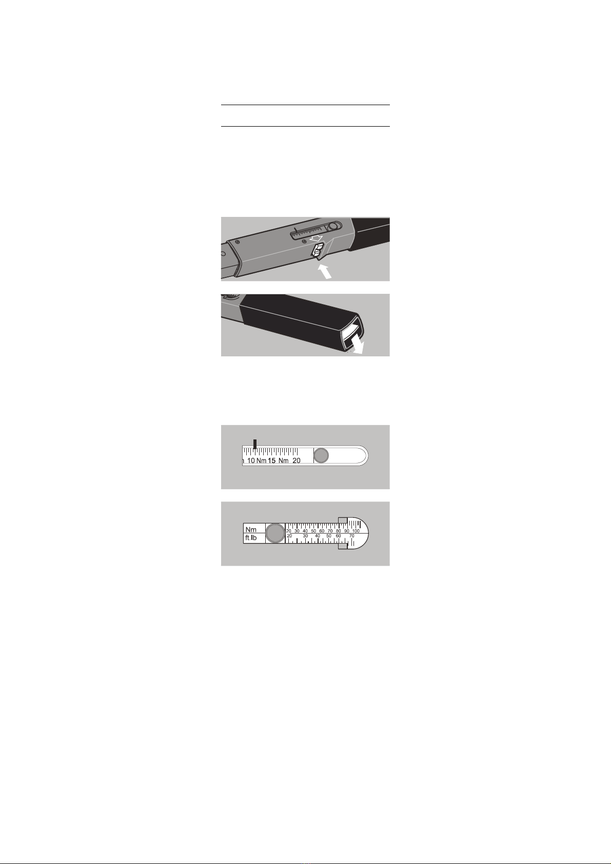
Proceed as follows:
1. Depress the button on the underside of
the tool, or the pressure plate in the
end of the handle as appropriate, to
release the setting fail-safe
mechanism.
2. Slide the scale to a torque level lower
than the desired cut-out value.
3. Now slide the scale to the desired cut-
out value.

41
4. Release the button / pressure plate.
The torque level is now set.
5. Check the value again. If the setting is
wrong, return to 1.
Controlled counter
clockwise tightening
For reasons of accuracy, these torque
wrenches have been designed to work in
only one direction. The direction is
marked with an arrow.
Controlled counter clockwise tightening is
possible by turning the MANOSKOP®
over. Exceptions: The MANOSKOP®
721/5, 721/15 and 721/20 cannot be used
for counter clockwise tightening.
For controlled counter clockwise
tightening using the MANOSKOP®
721/30 in the turned over position, the
square drive must first be pushed through
to the upper side.

EN
42
For controlled counter clockwise
tightening using the MANOSKOP® 730/2
to 730/65, the insert tool has to be rotated
through 180°. Ratchet insert tools also
need switching to „L“ (CCW) for the
correct tightening direction.
Uncontrolled loosening of
nuts & bolts ...
... opposite to the tightening direction is
possible. The cut-out mechanism is not
placed under load during this process.
Using the torque wrench
ATTENTION!
Exceeding the limit torque leads
to the risk of the torque wrench
becoming damaged.
Make sure that a limit torque of
approx. 130 % of the maximum
scale value is not exceeded.
Do not loosen any tightly rusted
bolts using the torque wrench.
CAUTION
An incorrect trigger value
leads to a risk of injury.
Make sure that the
correct trigger value is
set.
CAUTION
Unsecured plug-in tools
lead to a risk of injury.
Make sure that plug-in
tools are always secured
against pulling out by
engaging the retaining
pin.
43
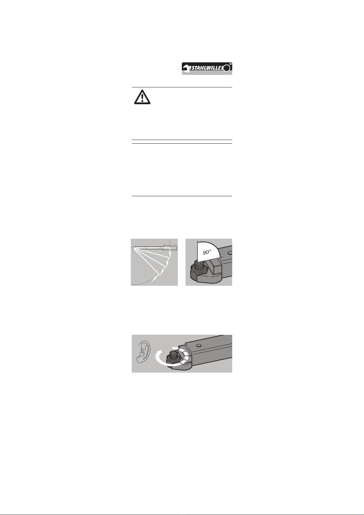
Only apply force to the MANOSKOP®via
its handle. Hold the handle in the middle.
Apply force at a tangent to the swivel
radius and at right angles to the axis of the
nut or bolt.
Pull steadily and without any interruption,
particularly during the final phase, until
you feel a jerk and hear a click. The torque
level set on the scale has now been
reached.
CAUTION
Slipping tools lead to a
risk of injury.
Make sure that the tool
cannot slip off the
workpiece.
ATTENTION!
Unsecured plug-in tools lead to a
risk of material damage.
Make sure that plug-in tools are
always secured against pulling out
by engaging the retaining pin.

EN
44
As soon as the torque wrench has cut out,
it is ready for the next job.
Maintenance
The internal mechanisms of the torque
wrench are subject to normal wear and
tear under operating conditions. For this
reason, the accuracy of the cut-out should
be checked at regular intervals.
Unless internal regulations at the place of
use say otherwise (e.g. test equipment
inspection to ISO 9000 et seq.) inspection
should take place after approx. 5000 uses
or every 12 months, whichever is the
shorter.
If inspection shows that there is a
deviation, the torque wrench must be
adjusted.
The inspection and adjustment must be
carried out in accordance with
DIN EN ISO 6789.
ATTENTION!
Incorrect use of the torque
wrench leads to the risk of
material damage.
Make sure that the tightening
process is immediately ceased
after the torque wrench has
triggered.

45
Checking the accuracy of
the cut-out value
A torque tester is necessary for the
inspection with sufficient capacity for the
wrench to be tested and with a
guaranteed accuracy of ± 1% of the
displayed reading.
If you have access to such a tester, you
may inspect the MANOSKOP®yourself.
Suitable torque testers are available from
STAHLWILLE. It is also possible for
STAHLWILLE to test the MANOSKOP®
for you.
To carry out the test, proceed as follows:
1. Set the torque wrench to the highest
scale reading.
2. Operate the torque wrench five times
ensuring it cuts out properly each time.
3. Set the torque wrench to 20% of the
maximum scale reading.
4. Operate the torque wrench five times
on the torque tester. Check o see that
the readings shown on the torque
tester are not more than 4.15% greater
and not more than 3.85% smaller than
the value set on the torque wrench.
ATTENTION!
Incorrect use of the torque
wrench leads to the risk of
material damage.
Make sure that the tightening
process is immediately ceased
after the torque wrench has
triggered.

EN
46
5. Set the torque wrench to 60% of the
maximum scale reading.
6. Operate the torque wrench five times
on the torque tester. Check to see that
the readings shown on the torque
tester are not more than 4.15% greater
and not more than 3.85% smaller than
the value set on the torque wrench.
7. Set the torque wrench to the highest
scale reading.
8. At this setting, operate the torque
wrench five times on the torque tester.
Check to see that the readings shown
on the torque tester are not more than
4.15% greater and not more than
3.85% smaller than the value set on
the torque wrench.
If the tests show that there are deviations
greater than the permitted amounts, the
wrench will require readjusting.
Adjusting for deviations in
cut-out value
You may return your torque wrench to
STAHLWILLE for adjustment. You will
then receive the tool back with a new
works calibration certificate.
You may adjust the torque wrench
yourself. In this case, however,
STAHLWILLE‘s accuracy guarantee is
void.
47
A torque tester is necessary for the
inspection with sufficient capacity for the
wrench to be tested and with a
guaranteed accuracy of ± 1% of the
displayed reading.
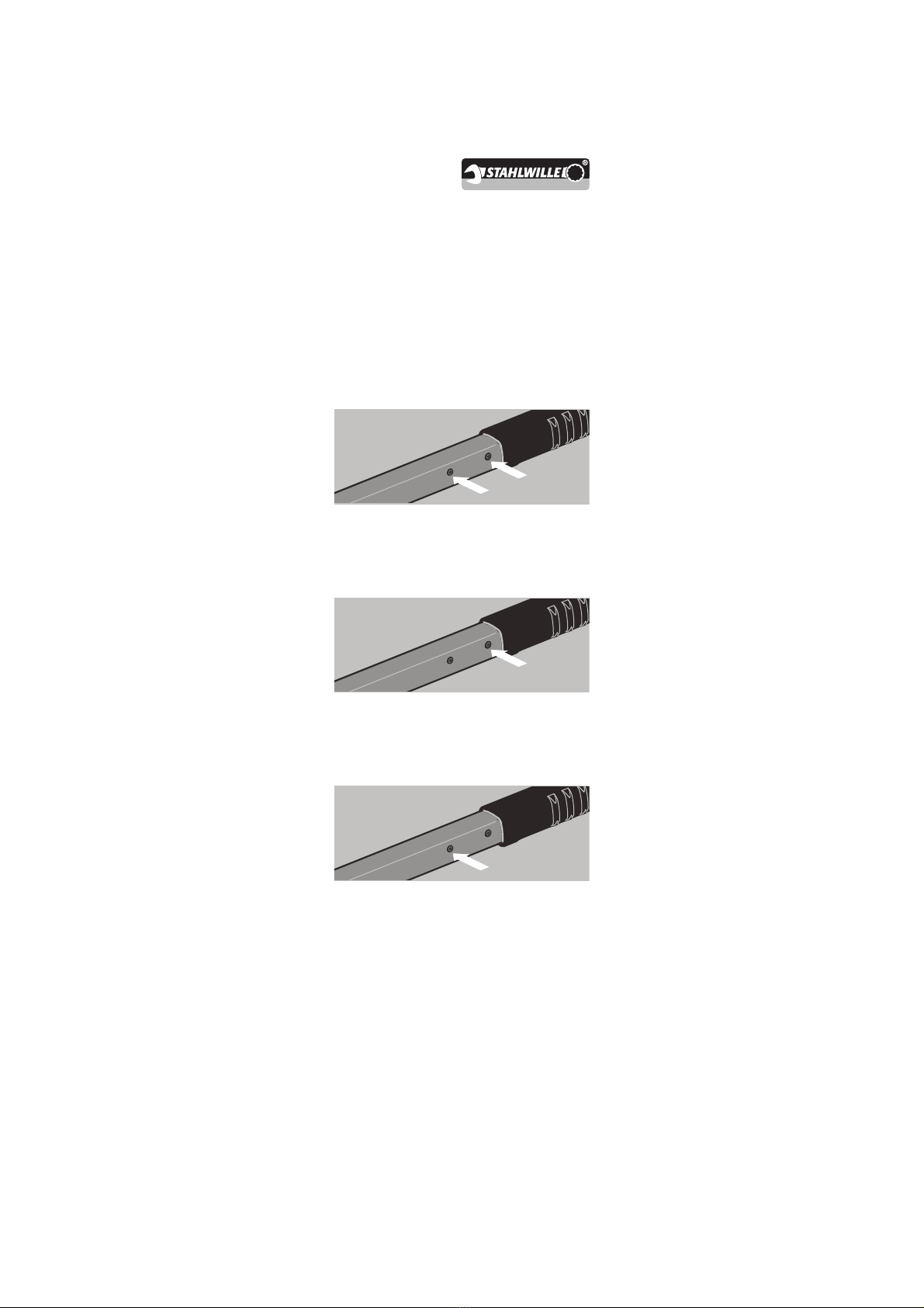
Every MANOSKOP®has two adjusting
screws inside for readjustment purposes.
These are accessible with an Allen key,
size 2 mm, through two holes in the
housing.
The screw which is closest to the end of
the handle is primarily for adjusting the
lower end of the scale range.
The screw which is closest to the head is
primarily for adjusting the upper end of the
scale range.
Each screw has a minor effect on the
adjusting range of the other screw.
To protect the mechanisms from dirt,
these two holes are plugged. The
MANOSKOP®730/2 and 730/4 have the
holes under the removable plastic cover
for protection.
To adjust the wrench, you will need the
torque tester and an Allen key, size 2 mm.
This manual suits for next models
19
Table of contents
Other Stahlwille Tools manuals

Stahlwille
Stahlwille multipower MP100-1500 User manual

Stahlwille
Stahlwille multipower MP100-1500 User manual

Stahlwille
Stahlwille SMARTCHECK USB/DAPTIQ User manual

Stahlwille
Stahlwille perfectControl 7794-2 User manual

Stahlwille
Stahlwille Manoskop 730N User manual

Stahlwille
Stahlwille TORSIOTRONIC TT 120 User manual

Stahlwille
Stahlwille Manoskop 730N User manual

Stahlwille
Stahlwille MANOSKOP 755R/1 Manual

Stahlwille
Stahlwille MULTIPOWER MP300 User manual

Stahlwille
Stahlwille MANOSKOP 730D User manual


