6 7
• Vehicles that have on-board computerized systems may be damaged if vehicle
battery is jump-started. Before jump-starting, read the vehicle’s owner’s manual to
confirm that external-starting assistance is suitable.
• Never smoke or allow a spark or flame in vicinity of vehicle battery, engine or
power station.
• Stay clear of fan blades, belts, pulleys, and other parts that can cause injury to
persons.
• Remove personal metal items such as rings, bracelets, necklaces and watches when
working with a lead acid battery. A lead acid battery can produce a short circuit
current high enough to weld a ring, or similar metal object, to skin, causing a
severe burn.
• Do not wear vinyl clothing when jump-starting a vehicle. Friction can cause
dangerous static-electrical sparks.
• Be extra careful to avoid dropping a metal tool onto the battery. It might spark or
short-circuit the battery or another electrical part and could cause an explosion.
• Jump-start procedures should only be performed in a safe, dry, well-ventilated area.
• Always store battery clamps when not in use. Never touch battery clamps together.
This can cause dangerous sparks, power arcing and/or explosion.
• When using this unit close to the vehicle’s battery and engine, stand the unit on a
flat, stable surface, and be sure to keep all clamps, cords, clothing and body parts
away from moving vehicle parts.
• Never allow red and black clamps to touch each other or another common
metal conductor – this could cause damage to the unit and/or create a sparking/
explosion hazard.
• If the clamps are connected incorrectly with regard to polarity, the backlit LCD
screen will display the Battery Status Icon, Battery Voltage Indicator, and the Clamp
Icons. The Alarm Icon, the “+” and ”–” signs and the Reverse Polarity Icons will
flash and the unit will sound a continuous alarm until the clamps are disconnected.
Disconnect the clamps and reconnect to battery with correct polarity.
• Always disconnect the negative (black) jumper cable first, followed by the positive
(red) jumper cable, except for positive grounded systems.
• Do not expose battery to fire or intense heat since it may explode. Before
disposing of the battery, protect exposed terminals with heavy-duty electrical tape
to prevent shorting (shorting can result in injury or fire).
• Place this unit as far away from the battery as cables permit.
• Never allow battery acid to come in contact with this unit.
• Do not operate this unit in a closed area or restrict ventilation in any way.
• This system is designed to be used only on vehicles with a 12 volt DC battery
system. Do not connect to a 6 volt or 24 volt battery system.
• This system is not designed to be used as a replacement for a vehicular battery. Do
not attempt to operate a vehicle that does not have a battery installed.
• Excessive engine cranking can damage a vehicle’s starter motor. If the engine
fails to start after the recommended number of attempts, discontinue jump-start
procedures and look for other problems that may need to be corrected.
• Do not use this Jump-Starter on a watercraft. It is not qualified for marine
applications.
• Although this unit contains a non-spillable battery, it is recommended that unit be
kept upright during storage, use and recharging. To avoid possible damage that
may shorten the unit’s working life, protect it from direct sunlight, direct heat and/
or moisture.
SPECIFIC SAFETY INSTRUCTIONS FOR INVERTERS
WARNING – To reduce the risk of electric shock:
• Do not connect to AC distribution wiring.
• Do not make any electrical connections or disconnections in areas designated as
IGNITION PROTECTED. This inverter is NOT approved for ignition protected areas.
• Never immerse the unit in water or any other liquid, or use when wet.
WARNING – To reduce the risk of fire:
• Do not operate near flammable materials, fumes or gases.
• Do not expose to extreme heat or flames.
CAUTION – To reduce the risk of injury or property damage:
• Disconnect appliance plug from the inverter outlet before attempting any repairs
to the appliance.
• When an appliance plugged into this unit is used outdoors, use only extension
cords intended for use outdoors and so marked.
• Do not attempt to connect the inverter while operating your vehicle. Not paying
attention to the road may result in a serious accident.
• Always use the inverter where there is adequate ventilation.
• Always turn the inverter off when not in use.
• Keep in mind that this inverter will not operate high wattage appliances or
equipment that produce heat, such as hair dryers, microwave ovens and toasters.
• Do not use this inverter with medical devices. It is not tested for medical
applications.
• Do not insert foreign objects into the inverter outlet.
• Do not attach AC outlet taps or multi-outlet extension cords, or attach more than
one electrical appliance to the inverter outlet.
• Operate inverter only as described in this Instruction Manual.
SPECIFIC SAFETY INSTRUCTIONS FOR THE USB PORT
• Do not insert foreign objects into the USB Ports.
• Do not attach USB hubs or more than one personal electronic device to each USB
Port.
• Some household USB-powered electronics will not operate with this unit.
SPECIFIC SAFETY INSTRUCTIONS FOR COMPRESSORS
WARNING – Burst hazard:
• Bursting articles can cause serious injury.
• Carefully follow instructions on articles to be inflated.
• Never exceed the recommended pressure listed in instructions on articles to be
inflated. If no pressure is given, contact article manufacturer before inflating.
• Monitor the pressure at all times on the pressure gauge.
CAUTION – To reduce the risk of injury or property damage:
• Never leave the compressor unattended while in use.
• Do not operate compressor continuously for longer than approximately 10
minutes, depending on ambient temperatures, as it may overheat. This could
damage the compressor.
PERSONAL SAFETY
When working with lead acid batteries, always make sure immediate assistance is
available in case of accident or emergency.
Always have protective eyewear when using this product: contact with battery acid
may cause blindness and/or severe burns. Be aware of first aid procedures in case of
accidental contact with battery acid.
Have plenty of fresh water and soap nearby in case battery acid contacts skin.
• SKIN: If battery acid comes in contact with skin, rinse immediately with water,
then wash thoroughly with soap and water. If redness, pain, or irritation occurs,
seek immediate medical attention.
• EYES: If battery acid comes in contact with eyes, flush eyes immediately, for a
minimum of 15 minutes and seek immediate medical attention.
• LCD LIQUID CRYSTAL DISPLAY: If liquid crystal comes in contact with
your skin: Wash area off completely with plenty of water. Remove contaminated
clothing. If liquid crystal gets into your eye: Flush the affected eye with clean
water and then seek medical attention. If liquid crystal is swallowed: Flush
your mouth thoroughly with water. Drink large quantities of water and induce
vomiting. Then seek medical attention.
INTRODUCTION
Congratulations on purchasing your new 1000A Power Bank. Read this
Instruction Manual and follow the instructions carefully before using this
unit.
SAVE THESE INSTRUCTIONS
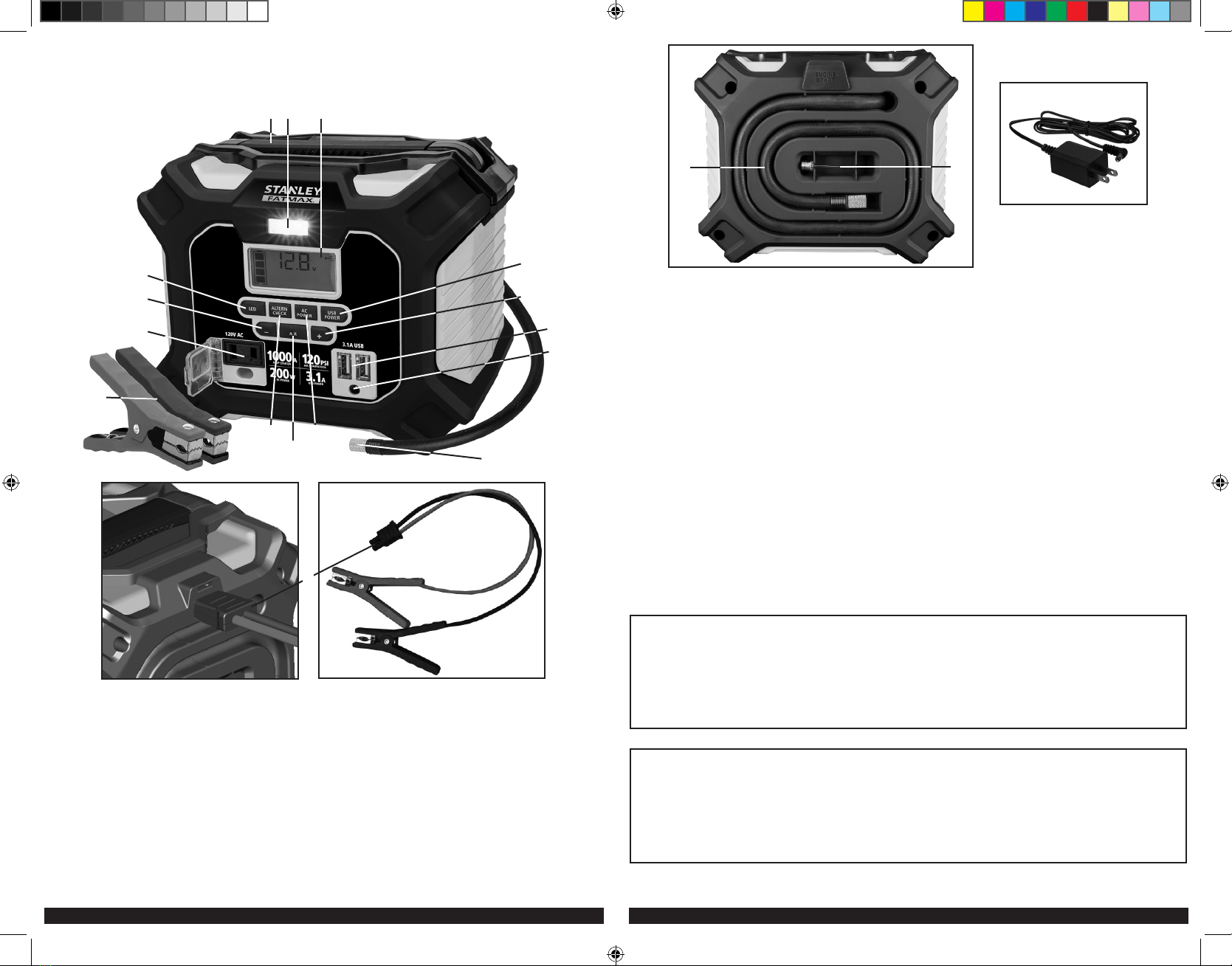
OVERVIEW
Common Actions and Unit Responses
The following actions turn the unit on and activate the LCD screen:
Press the LED Area Light
Power Button. (Refer
to the “LED Area Light”
section.)
A beep will sound and the Area Light will turn on.
The backlight will turn on for 10 seconds (only).
The LCD screen will continue to display the Battery
Status Icon and Battery Voltage Indicator. The unit
remains on until the LED Area Light Power Button is
pressed again to turn it off.
Press the Alternator
Check Button. (Refer to
the “Alternator Check”
section.)
A beep will sound and the backlit LCD screen will
display the Battery Status Icon, and the Alternator
Icon will flash. The unit remains on until the
Alternator Check Button is pressed again to turn
it off.
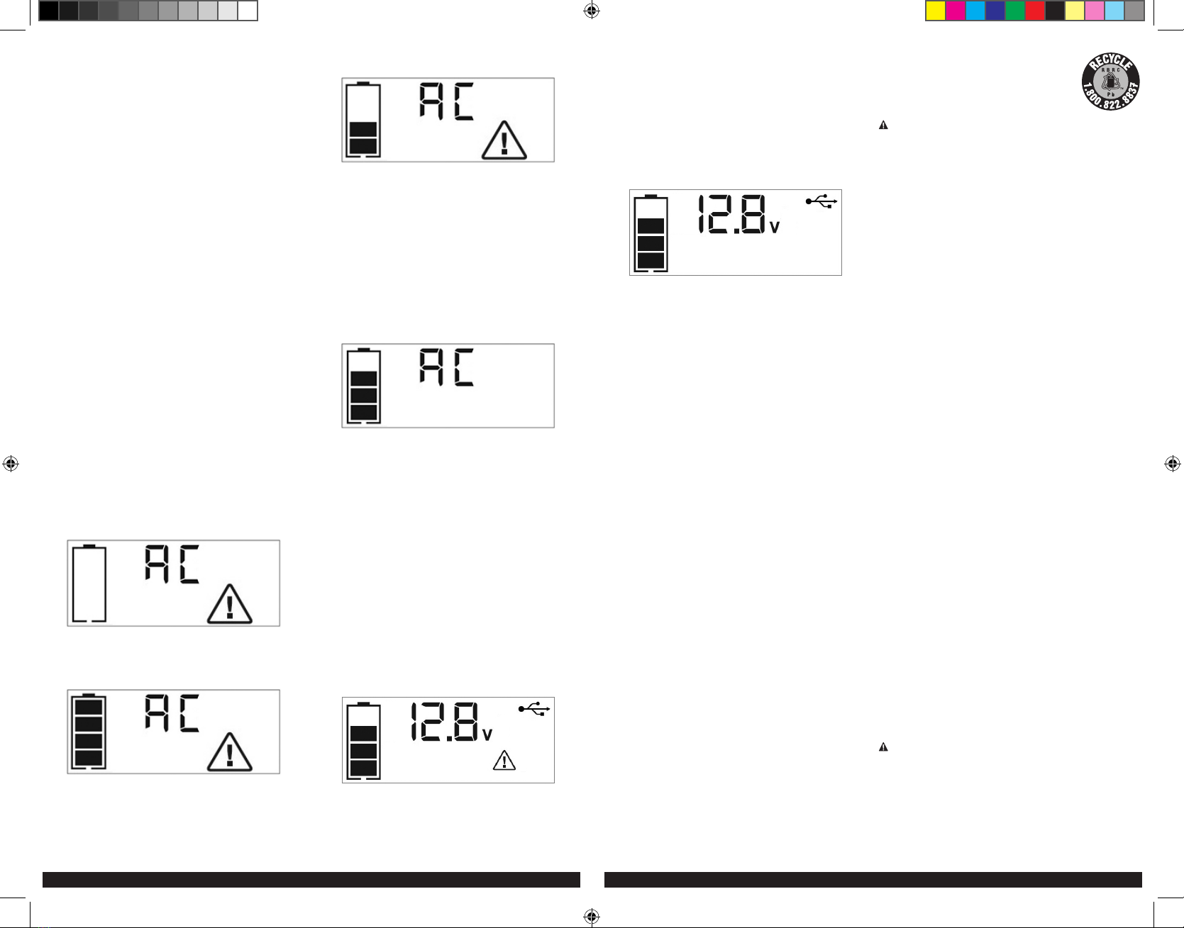
Press the AC Power
Button. (Refer to the
“120V AC Power Outlet”
section.)
A beep will sound and the backlit LCD screen will
display the Battery Status Icon; and the Digital
Display shows “AC”, indicating the AC outlet is
ready to use. The unit remains on until the AC
Power Button is pressed again to turn it off.
Press the USB Power
Button. (Refer to the “USB
Ports” section.)
A beep will sound and the backlight will turn on for
10 seconds (only). The LCD screen will display the
Battery Status Icon, Battery Voltage Indicator, and
the USB Icon; and the USB Power/Fault Indicators
will light solid blue indicating the four USB Ports
are active. The unit remains on until the USB Power
Button is pressed again to turn it off.
Press the Compressor
Power Button. (Refer to
the “Portable Compressor”
section.)
A beep will sound and the backlit LCD screen will
display the Battery Status Icon, “XXX” PSI and the
Compressor Icon. If no further actions are taken
after 1 minute, the unit will display the Battery
Status Icon and Battery Voltage Indicator for 10
seconds before automatically turning off.
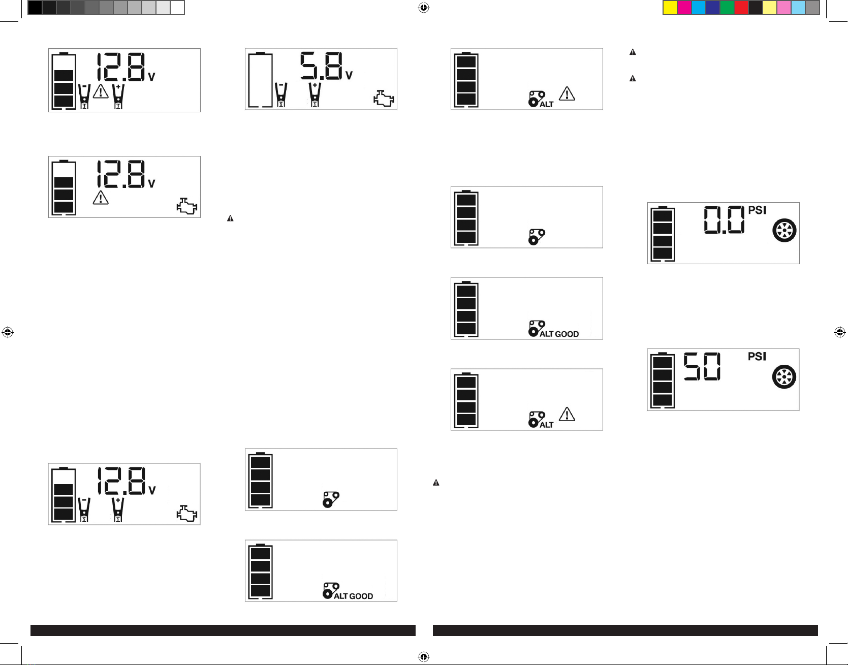
Whenever the clamps
are properly connected
to a battery (refer to the
“Jump-Starter” section) …
… a beep will sound and the backlit LCD screen
will display the Battery Status Icon, Battery Voltage
Indicator, the Clamp Icons, and the “+” and ”–”
signs, as well as the flashing Jump-Starter Icon. The
unit remains on until the clamps are disconnected
from the battery.
If the red and black
clamps touch each
other (refer to the “Jump-
Starter” section) …
… the backlit LCD screen will display the Battery
Status Icon and Battery Voltage Indicator. The Clamp
Icons, “+” and ”–” signs and the Alarm Icon will
flash. The unit will sound a two-second warning
every ten seconds continuously until the clamps are
separated.
If the clamp connections
to the battery’s positive
and negative terminals
are reversed (refer to the
“Jump-Starter” section) …
… the backlit LCD screen will display the Battery
Status Icon, Battery Voltage Indicator, and the Clamp
Icons. The Alarm Icon, the “+” and ”–” signs and
the Reverse Polarity Icons will flash and the unit will
sound a warning continuously until the clamps are
disconnected from the battery.
When the unit is
charging or recharging
using the supplied
Charging Adapter
(refer to the “Charging/
Recharging” section) …
… the backlight will turn on for 10 seconds (only).
The LCD screen will continue to display the Battery
Status Icon and Battery Voltage Indicator. The bars
on the Battery Status Icon will change from empty
to solid (bottom to top) repeatedly.
Note: The unit will automatically power off once ALL the functions are turned off.
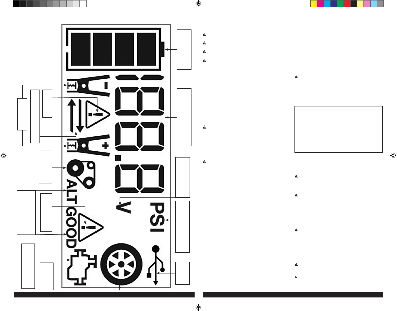
VIEWING BATTERY STATUS
The Battery Status Icon and Battery Voltage Indicator indicate the battery charge
level as follows.
• If the battery charge level is at full capacity, four solid bars will display.
• If the battery is partially charged, two or three solid bars will display.
• If the battery is nearly empty, one solid bar will display. The unit should be
charged at this time.
• If the battery is completely empty, four blank bars will display. The unit MUST be
charged at this time or the unit’s built-in low voltage protection will activate. The
empty Battery Status Icon will flash for a short period of time before automatic
shut down. The unit will not operate until the battery is recharged.
CHARGING/RECHARGING
Lead-acid batteries require routine maintenance to ensure a full charge and long
battery life. All batteries lose energy from self-discharge over time and more
rapidly at higher temperatures. Therefore, batteries need periodic charging to
replace energy lost through self-discharge. When the unit is not in frequent use,
manufacturer recommends the battery should be recharged at least every 30 days
and after each use.
IMPORTANT CHARGING NOTES
1. This unit is delivered in a partially charged state – you must fully charge it
before using it for the first time. Initial AC charge should be for 20 hours or
until the Battery Status Icon shows 4 solid bars.
2. Recharging the battery after each use will prolong battery life; frequent heavy
discharges between recharges and/or overcharging will reduce battery life.
3. Make sure all other unit functions are turned off during recharging, as this can
slow the recharging process.
Failure to keep the battery charged will cause permanent damage and result in
poor Jump-Starting performance.
IMPORTANT: If you know the unit is discharged, but the battery icon displays four
solid bars as if the unit is fully charged when connected to a charging power source,
this may be due to the internal battery having high impedance. The manufacturer
suggests leaving the unit charging for a period of 20 hours using the supplied AC
charger before use.
Charging/Recharging Using the Supplied Charging
Adapter
1. Insert the barrel connector of the AC charging adapter into the AC charging
port on the front of the unit (refer to Fig. 2 to locate). Insert the plug end into
a (powered) standard North American 120 volt 60Hz outlet. When the unit
is properly connected to an AC power source, the LCD screen will display the
following:
The bars on the Battery Status Icon represent the charge level of the unit’s
internal battery. The bars on the Battery Status Icon will change from empty to
solid (bottom to top) repeatedly to indicate the unit is charging. The backlight
will turn on for 10 seconds (only).
2. Charge for approximately 20 hours or until the Battery Status Icon shows 4
solid bars.
3. When charging is complete, disconnect the AC charging adapter – first unplug
the adapter from the AC power source, then disconnect the barrel connector
from the unit.
JUMP-STARTER
IMPORTANT: All features must be turned
off with the exception of the area light
when jump-starting. The unit is intended to
be used only in the upright position. The
unit must be kept upright during use. See
the illustration to the right for correct
orientation.
WARNING – To reduce the risk of serious injury or property damage:
• Follow all safety instructions found in the “Specific Safety Instructions for Jump-
Starters” section of this instruction manual.
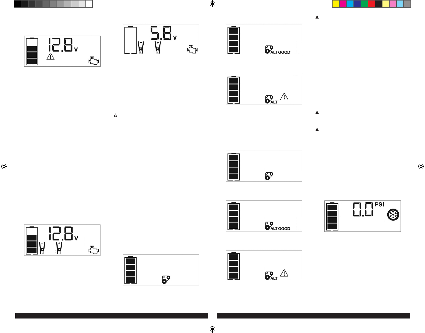
• If the clamps are connected incorrectly with regard to polarity, the unit will sound
a continuous alarm until the clamps are disconnected. The backlit LCD Screen will
display the Battery Status Icon, the Battery Voltage Indicator and the Clamp Icons.
The “+” and “–” signs above the Clamp Icons, the Reverse Polarity Icons and the
Alarm Icon will flash. The backlit LCD screen will display the following:
Disconnect the clamps and reconnect to battery with correct polarity.
• Never touch red and black clamps together. This can cause dangerous sparks,
power arcing, and/or explosion. If the red and black clamps touch each other, the
PPS200S_ManualENSP_072621.indd 6-7PPS200S_ManualENSP_072621.indd 6-7 7/26/2021 9:44:20 AM7/26/2021 9:44:20 AM