Star Lake THOR100-X4 User manual

Version 1.0
Revision Date: 03.21.2022
Quick Installation Guide
MIL-STD-810 Military Computer
1U 1/2 Size Intel Xeon E-2276ML
processor, MIL-STD-461 EMI 18-
36V DC-In
THOR100-X4

Safety information
Electrical safety
u
To prevent electrical shock hazard, disconnect the power cable from the electrical outlet
before relocating the system.
u
When adding or removing devices to or from the system, ensure that the power cables for
the
devices are unplugged before the signal cables are connected. If possible, disconnect all power
cables from the existing system before you add a device.
u
Before connecting or removing signal cables from the motherboard, ensure that all power
cables are unplugged.
u
Seek professional assistance before using an adapter or extension cord. These devices could
interrupt the grounding circuit.
u
Make sure that your power supply is set to the correct voltage in your area.
u
If you are not sure about the voltage of the electrical outlet you are using, contact your local
power company.
u If the power supply is broken, do not try to fix it by yourself. Contact a qualified service
technician or your local distributor.
Operation safety
u
Before installing the motherboard and adding devices on it, carefully read all the manuals
that came with the package.
u
Before using the product, make sure all cables are correctly connected and the power cables
are not damaged. If you detect any damage, contact your dealer immediately.
u
To avoid short circuits, keep paper clips, screws, and staples away from connectors, slots,
sockets and circuitry.
u Avoid dust, humidity, and temperature extremes. Do not place the product in any area
where it may become wet.
u
Place the product on a stable surface.
u
If you encounter any technical problems with the product, contact your local distributor
Statement
u All rights reserved. No part of this publication may be reproduced in any form or by any
means, without prior written permission from the publisher.
u
All trademarks are the properties of the respective owners.
u
All product specifications are subject to change without prior notice

Revision History
Revision
Date (yyyy/mm/dd)
Changes
Version 1.0
2022/03/21
Initial release
Packing list
u
THOR100-X4 1U 1/2 Rugged Military System
u
CD (Driver + Quick Installation Guide)
Ordering information
Model Number
De
Scription]
THOR100X4-D10
MIL-STD Fanless Rugged Computer with Intel® 9th Gen Xeon® E-
2276ML, IP65, with 10 MIL-DTL-D38999 Connectors, Operating Temp.
-40 to 70°C
THOR100X4-D9
MIL-STD Fanless Rugged Computer with Intel® 9th Gen Intel® Core i7-
9850HL, IP65, with 10 MIL-DTL-D38999 Connectors, Operating Temp.
-40 to 70°C
If any of the above items is damaged or missing, please contact your local distributor.

Table Contents
SAFETY INFORMATION
..............................................................................................................................................................
2
E
LECTRICAL SAFETY
..........................................................................................................................................................................................................................
2
O
PERATION SAFETY
...........................................................................................................................................................................................................................
2
STATEMENT
..................................................................................................................................................................................
2
REVISION HISTORY
....................................................................................................................................................................
3
PACKING LIST
..............................................................................................................................................................................
3
ORDERING INFORMATION ............................................................................................................................................. 3
TABLE CONTENTS
.................................................................................................................................................................................
4
CHAPTER 1: PRODUCT INTRODUCTION
.............................................................................................................................
5
•
K
EY
F
EATURES
................................................................................................................................................................................................................
5
• DIMENSIONS .............................................................................................................................................................................................. 6
CHAPTER 2: JUMPERS AND CONNECTORS LOCATIONS
..............................................................................................
7
u
C
ONNECTOR
P
IN
D
EFINITIONS
................................................................................................................................................................................
7
Connector X1, X2, X3, X4, X5 ..................................................................................................................................... 8
Connector X6, X7, X8, X9, X10 .................................................................................................................................... 9
CHAPTER 3: BIOS SETUP
...............................................................................................................................................................
10-50
Chapter 1: Product Introduction
l
Key Features
System
CPU
Intel® 9
th
Gen. XEON E-2276ML Processor (12M Cache,
Base Frequency 20GHz; Max Turbo Frequency 4.2GHz)
Memory Type
4 x DDR4 2666MHz up to 128GB
Processor Graphics
Intel® UHD Graphics P630
BIOS
AMI® BIOS
Storage Device
1x M.2 2280 NVMe up to 2TB
Digital Input/Output
8 bit digital I/O, split into 2 groups of 4. Programmable I/O
Front
I/O
DC In
1 x Amphenol TV06RW-09-98P
DIO
1 x 3 DIO Mic-In/Line Out Amphenol TV07RW-13-35SD
LAN
1 x Amphenol TV07RW-09-09S
LAN
1 x Amphenol TV07RW-09-09S
LAN
1 x Amphenol TV07RW-09-09S
Power Button with LED backlight
Rear
I/O
DVI
1 x Amphenol TV07RW-13-35S
DVI
1 x Amphenol TV07RW-13-35S
USB 3.0
1 x Amphenol USB3FTV7AZNF312
USB 3.0
1 x Amphenol USB3FTV7AZNF312
USB 3.0
1 x Amphenol USB3FTV7AZNF312
Applications
Applications
1U Half Size Rugged Mission MIL-STD 810 Computer is built to meet strict size,
weight, and power (SWaP) requirements and to withstand harsh environments,
including temperature extremes, shock/vibe, sand/dust, and salt/fog.
Operation System
OS Support
Windows 10 64bit, Windows server 2019 64bit, Windows 2016 64bit, Hyper-V
Server 2016 R2, Ubuntu 16.04.3 LTS/17.10/18.04.1 LTS, Fedora 25/26, RedHat
Linux EL 6.8/6.9/7.3/7.4/7.6, VMware ESXi6.5u1, VMware ESXi6.7u2
Mechanical & Environment
Chassis
Aluminum Alloy, Corrosion design
Finish
Anodic aluminum oxide
Cooling
Natural Passive Convection/Conduction. No Moving Parts
Ingress Protection
IP65
Power
Requirements
MIL-STD-461 EMI Power Supply, 18-36V DC In
Dimension
(W x
D
x H)
220 x 400 x 44mm
(8.6" x 15.7" x 1.7")
Operating Temp.
-40 to 70°C
Storage Temp.
-
40 to 85°C
Relative Humidity
5% to 95%, non
-
condensing
* Specifications are subject to change without notice*

•
Dimensions

•
Panel Component
1
DC In
label (X1)
2
DIO, label (X2)
3
LAN
, label (X3)
4
LAN
, label (X4)
5
LAN, label (X5)
6
DVI, label (X6)
7
DVI, label (X7)
8
USB 3.0, label (X8)
9
USB 3.0, label (X9)
10
USB 3.0, label (X10)

Chapter 2: Jumpers and Connectors Locations
l
D38999 Connector Pin Definitions
X1:DC-In
X2: DIO
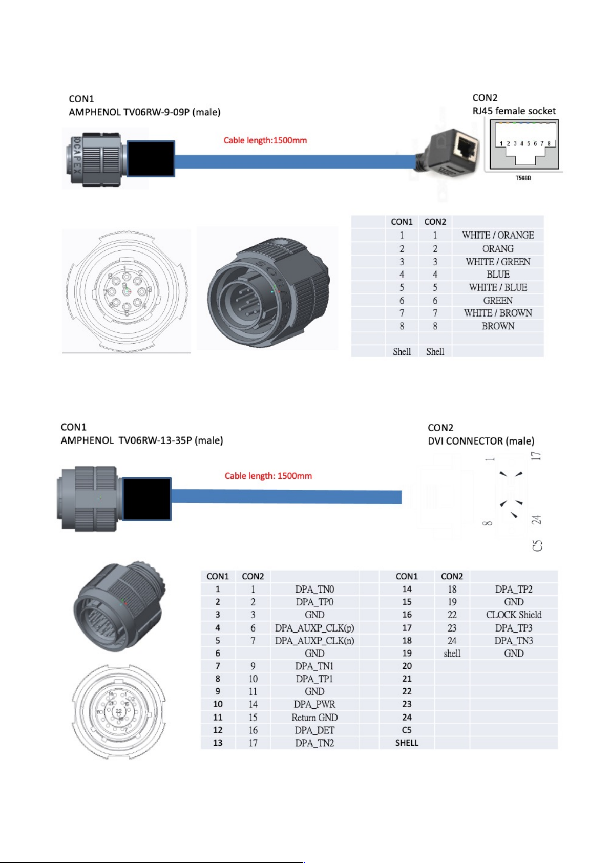
X3, X4, X5: LAN
X6, X7 DVI
!
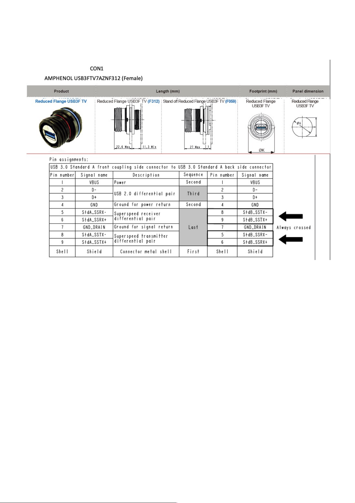
X8, X9, X10 USB 3.0
!
!
!
!
!
!
!
!
!
!
!
!
!
!
!
!
!
!

!
3: AMI BIOS UTILITY
This chapter provides users with detailed descriptions on how to set up a basic system configuration
through the AMI BIOS setup utility.
3.1 Starting
To enter the setup screens, perform the following steps:
• Turn on the computer and press the <Del> key immediately.
• After the <Del> key is pressed, the main BIOS setup menu displays. Other setup screens can be
accessed from the main BIOS setup menu, such as the Chipset and Power menus.
3.2 Navigation Keys
The BIOS setup/utility uses a key-based navigation system called hot keys. Most of the BIOS setup
utility hot keys can be used at any time during the setup navigation process.
Some of the hot keys are <F1>, <F10>, <Enter>, <ESC>, and <Arrow> keys.
Left/Right
The Left and Right <Arrow> keys moves the cursor to select a
menu.
Up/Down
The Up and Down <Arrow> keys moves the cursor to select a
setup screen or sub-screen.
+− Plus/Minus
The Plus and Minus <Arrow> keys changes the field value of a
particular setup setting.
Tab
The <Tab> key selects the setup fields.
F1
The <F1> key displays the General Help screen.
F10
The <F10> key saves any changes made and exits the BIOS
setup utility.
Esc
The <Esc> key discards any changes made and exits the BIOS
setup utility.
Enter
The <Enter> key displays a sub-screen or changes a selected or
highlighted option in each menu.
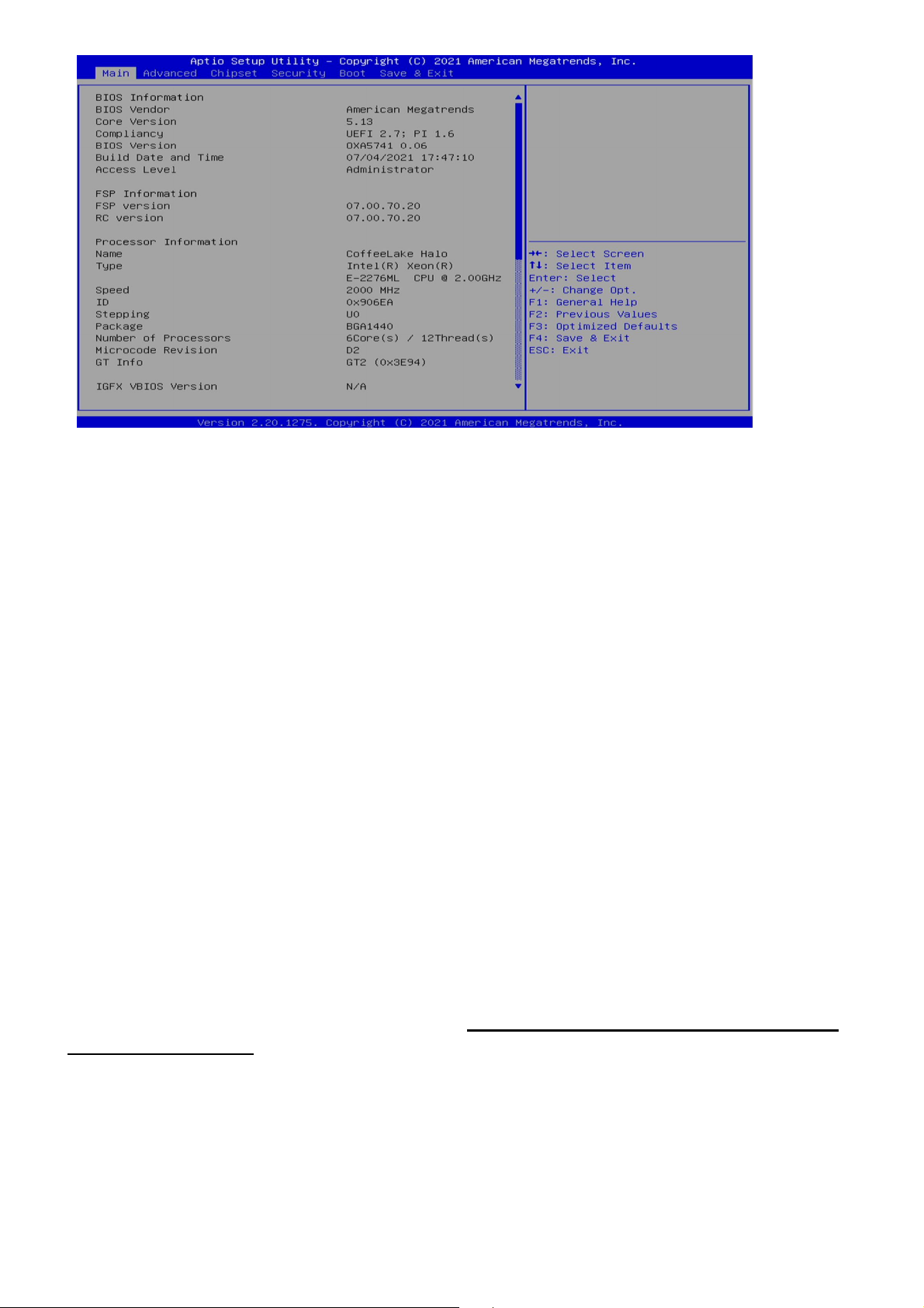
3.3 Main Menu
The Main menu is the screen that first displays when BIOS Setup is entered, unless an error has
occurred.
When you first enter the BIOS Setup Utility, you will encounter the Main setup screen. You can always
return to the Main setup screen by selecting the Main tab. There are two Main Setup options. They are
described in this section. The Main BIOS Setup screen is shown below.
The Main BIOS setup screen has two main frames. The left frame displays all the options that can be
configured. Grayed-out options cannot be configured; options in blue can. The right frame displays the
key legend. Above the key legend is an area reserved for a text message. When an option is selected in
the left frame, it is highlighted in white. Often a text message will accompany it.
l System Date
Use this function to change the system date.
Select System Date using the Up and Down <Arrow> keys. Enter the new values through the
keyboard. Press the Left and Right <Arrow> keys to move between fields.
The date setting must be entered in MM/DD/YY format.
l System Time
Use this function to change the system time.
Select System Time using the Up and Down <Arrow> keys. Enter the new values through the
keyboard. Press the Left and Right <Arrow> keys to move between idles.
The time setting is entered in HH:MM:SS format.
Note: The time is in 24-hour format. For example, 5:30 A.M. appears as 05:30:00, and 5:30 P.M. as
17:30:00.
l Access Level
Display the access level of the current user in the BIOS.
3.4 Advanced Menu
The Advanced Menu allows you to configure your system for basic operation. Some entries are defaults
required by the system board, while others, if enabled, will improve the performance of your system or let
you set some features according to your preference. Setting incorrect field values may cause the
system to malfunction.
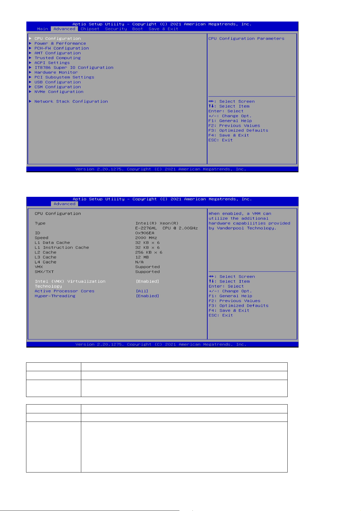
3.4.1 CPU Configuration
Field Name
Intel (VMX) Virtualization Technology
Default Value
[Enabled]
Possible Value
Disabled
Enabled
Field Name
Active Processor Cores
Default Value
[A11]
Possible Value
A11
1
2
3
4
5

3.4.2 Power & Performance
Field Name
Hyper-Threading
Default Value
[Enabled]
Possible Value
Disabled
Enabled
Field Name
Intel (R) SpeedStep(tm)
Default Value
[Enabled]
Possible Value
Disabled
Enabled
Field Name
Turbo Mode
Default Value
[Enabled]
Possible Value
Disabled
Enabled
Field Name
C states
Default Value
[Disabled]
Possible Value
Disabled
Enabled

3.4.4 AMT Configuration
Field Name
ME State
Default Value
[Enabled]
Possible Value
Disabled
Enabled
Field Name
Manageability Features State
Default Value
[Enabled]
Possible Value
Disabled
Enabled
Field Name
AMT BIOS Features
Default Value
[Enabled]
Possible Value
Disabled
Enabled

3.4.4.1 CIRA Configuration
3.4.4.2 ASF Configuration
Field Name
ASF support
Default Value
[Enabled]
Possible Value
Disabled
Enabled
Field Name
USB Provisioning of AMT
Default Value
[Disabled]
Possible Value
Disabled
Enabled
Field Name
Activate Remote Assistance Process
Default Value
[Disabled]
Possible Value
Disabled
Enabled

3.4.4.3 Secure Erase Configuration
Field Name
PET Progress
Default Value
[Enabled]
Possible Value
Disabled
Enabled
Field Name
WatchDog
Default Value
[Disabled]
Possible Value
Disabled
Enabled
Field Name
ASF Sensors Table
Default Value
[Disabled]
Possible Value
Disabled
Enabled

3.4.4.4 OEM Flags Settings
Field Name
Secure Erase mode
Default Value
[Simulated]
Possible Value
Simulated
Real
Field Name
Force Secure Erase
Default Value
[Disabled]
Possible Value
Disabled
Enabled
Field Name
MEBx hotkey Pressed
Default Value
[Disabled]
Possible Value
Disabled
Enabled
Field Name
MEBx Selection Screen
Default Value
[Disabled]
Possible Value
Disabled
Enabled
Field Name
Hide Unconfigure ME Confirmation Prompt
Default Value
[Disabled]
Possible Value
Disabled
Enabled
Field Name
MEBx OEM Debug Menu Enable
Default Value
[Disabled]
Possible Value
Disabled
Enabled

3.4.4.5 MEBx Resolution Settings
Field Name
Unconfigure ME
Default Value
[Disabled]
Possible Value
Disabled
Enabled
Field Name
Non
-
UI Mode Resoultion
Default Value
[Auto]
Possible Value
Auto
80x25
100x31
Field Name
UI Mode Resolution
Default Value
[Auto]
Possible Value
Auto
80x25
100x31
Field Name
Graphics Mode Resoultion
Default Value
[Auto]
Possible Value
Auto
640x480
800x600
1024x768
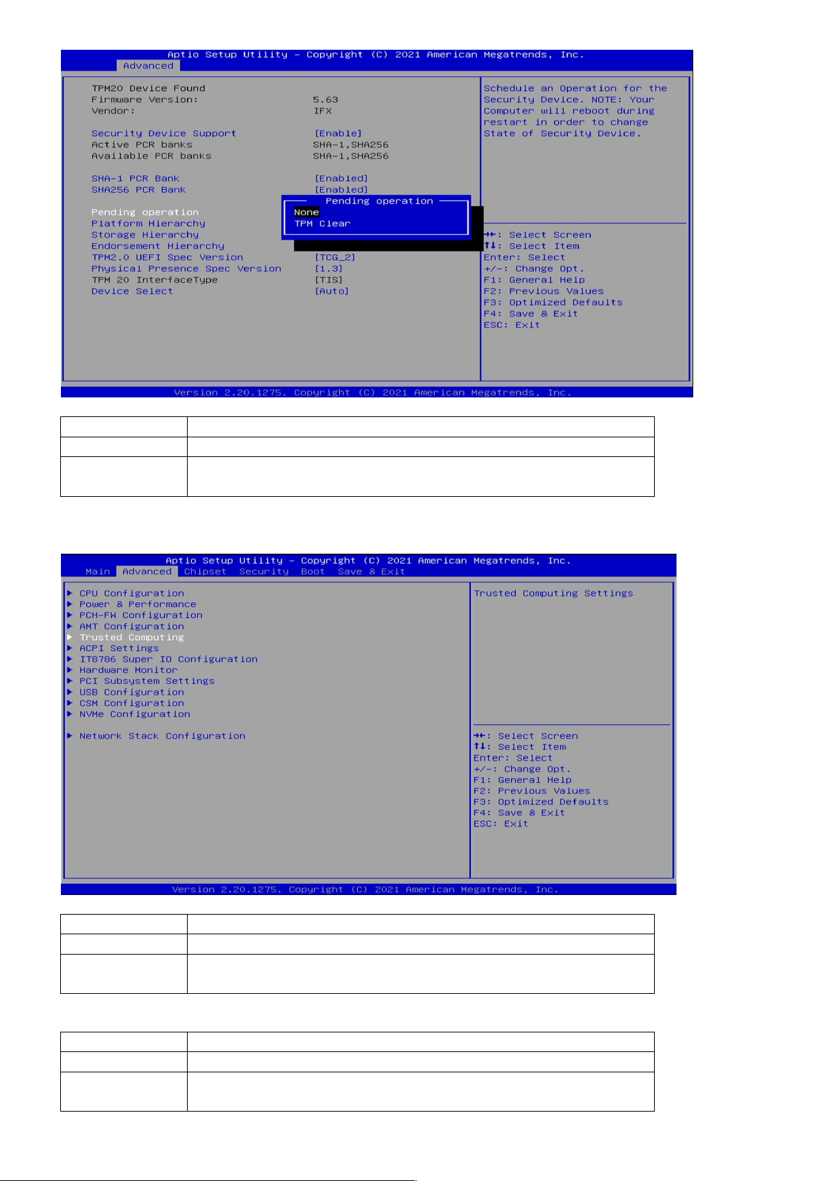
3.4.5 Trusted Computing
Field Name
Pending operation
Default Value
[None]
Possible Value
None
TPM Clear
Field Name
Security Device Support
Default Value
[Enabled]
Possible Value
Disabled
Enabled
Field Name
SHA
-
1 PCR Bank
Default Value
[Enabled]
Possible Value
Disabled
Enabled
This manual suits for next models
1
Table of contents
Other Star Lake Computer Hardware manuals

Star Lake
Star Lake INS8366A User manual

Star Lake
Star Lake AV710-X3 User manual

Star Lake
Star Lake OXY5361A User manual

Star Lake
Star Lake OXY5740A User manual

Star Lake
Star Lake OXY5362A User manual

Star Lake
Star Lake OXY5741B User manual

Star Lake
Star Lake SK220 User manual

Star Lake
Star Lake SK221 User manual

Star Lake
Star Lake OXY5363A User manual

Star Lake
Star Lake SR700-X4 User manual


