6. Hard Drive Requirements and Precautions
1. Only one interface connection may be used at once per one computer system.
2. When connected to the computer system, it’s prohibited to remove, insert or swap the hard drive while
data transfer is being performed.
3. It’s prohibited to change the positioning of the drives once the initial installation has been completed
as the changes made to the drive positions may destroy the RAID formation.
4. Whenever turning off or unplugging the SR5-WBS2 from your computer system becomes necessary,
always remember to safely remove it from your operating system first.
5. It is highly recommended for users to back up important data contained within the SR5-WBS2 on a
regular basis or whenever the user feels necessary at a remote or a separate storage device. STAR-
DOM is not responsible for any lost of data caused during the use of the SR5-WBS2 unit nor the re-
covery of the data lost.
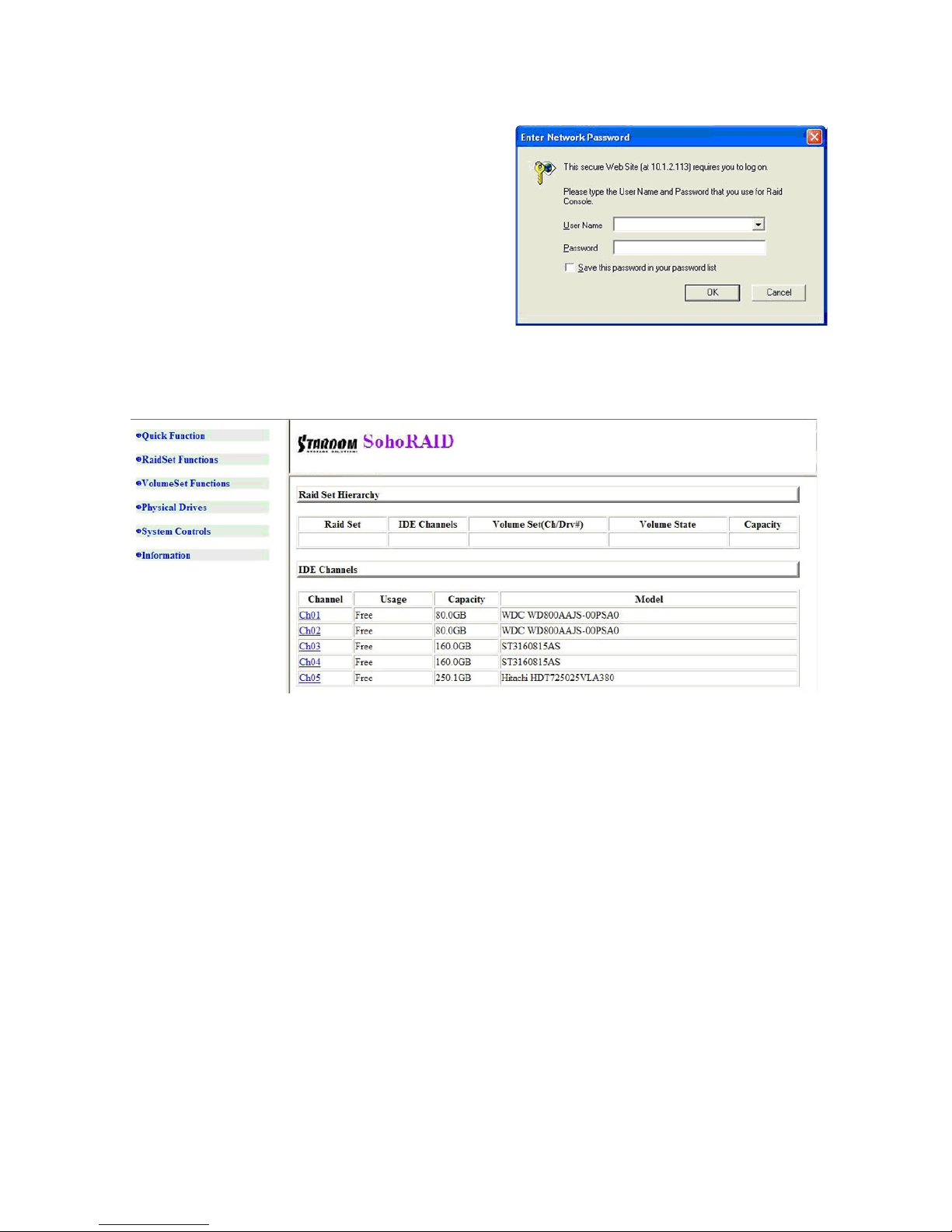
When your computer has booted, your operating system should recognize the RAID volume automatically.
After the volume has been successfully recognized, please follow the formatting of hard drive instructions
given by the operating system to format the drive volume of your preference. Once the formatting has been
completed, the RAID system is ready for use.
Note :
The actual storage capacities may differ from the stated capacities on the hard drives once the
drives have been formatted.
7. Drive Failures and Replacement Instructions
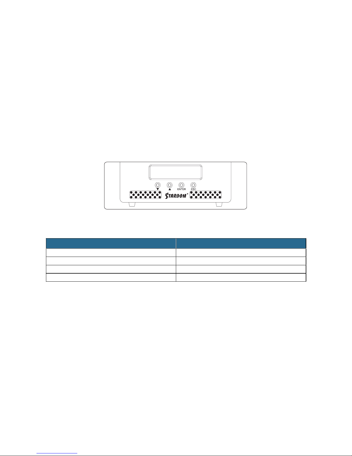
If one of the front hard drive indicator has lit up red and the audio alarm sounds, this could mean the indica-
tive hard drive has failed. If this occurs, you may mute the audio alarm ( refer to the System Controls > View
events > Mute Beeper ) to shut off the audio alarm and power off the system immediately if in the allowed
operational state then re-power on the system to double check and see if in fact the indicative hard drive has
failed. If the problem persists, please turn off the system and follow the directions below:
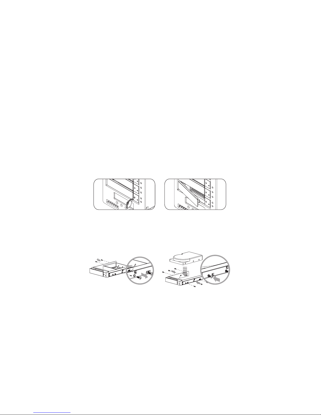
Step1 Remove the failed hard drive from its drive position.
Step2 Mount the new hard drive onto the tray and insert it back to the empty drive position, then push the
latch into place making sure it is secured and locked.
Step3 Turn the system on as the hard drive status indicator of the replacement drive will blink red twice per
second. During data rebuild, you may use the SR5-WBS2 normally.
Note :
When purchasing a new hard drive, it is recommended in purchasing the same brand and specifica-
tion as the other good drives or you may purchase one that's at least 20GB greater in capacity to
avoid the inability to complete the formation.
SOHORAID SR5 Series User Manual
!16