Stark NL 3200 Operating instructions

Original Instructions
User and Maintenance Manual
Articulated Plow

Page 2/ 30
Introduction
Congratulations for choosing STARK Articulated Plow!
We at the STARK want your plow to serve you the best possible way, efficiently and for a long time. Therefore, please
read this manual before taking your new plow in use.
STARK products are designed and manufactured in Finland and each attachment is equipped to meet the customer’s
needs.
Make sure that everyone using and servicing the plow reads this manual beforehand! Always ensure safety while using
and servicing the plow. Please keep this manual and make sure to pass it on to a possible new owner.
Development of STARK products is based on quality, durability and economical use. Products have been designed to be
efficient, safe and durable in professional use. Feedback and customer experience are important to us for our future
development. Also, if you have any questions regarding operation or maintenance of the plow please contact us by
email: [email protected]
New innovations and all our products can be found on our website: www.stark.fi
Manufacturer reserves the right to structural and technical changes without notice. Information in the manual may
therefore have changed after printing.
Read before use
Familiarise yourself with the attachment before taking it in use.
The plow should be operated only by proficient users.
People working with this attachment should be thoroughly introduced to operation
and maintenance of it. People not acquainted with the plow may cause danger to
themselves, environment or the attachment.
When connecting the attachment, please pay attention:
-that the locking pins and cotter pins are fine
-there is no pressure in the hydraulics system
-that the hydraulic hoses are intact
-when connecting the hydraulics avoid skin contact with hydraulic fluid
-do not pull from the hose, only from the coupling
While operating, please pay attention:
-safe and appropriate speed
-other traffic, people and animals
-danger zones and visual obstacles
-device should not be used when someone is in the danger zone
-be careful around children
-do not go under the attachment

Page 3/ 30
Contents
Introduction .........................................................................................................................................2
Read before use ...................................................................................................................................2
1. DECLARATION OF CONFORMITY......................................................................................................4
2. INTENDED USE .................................................................................................................................5
3. SAFETY INSTRUCTIONS.....................................................................................................................5
4. IDENTIFICATION AND PARTS............................................................................................................6
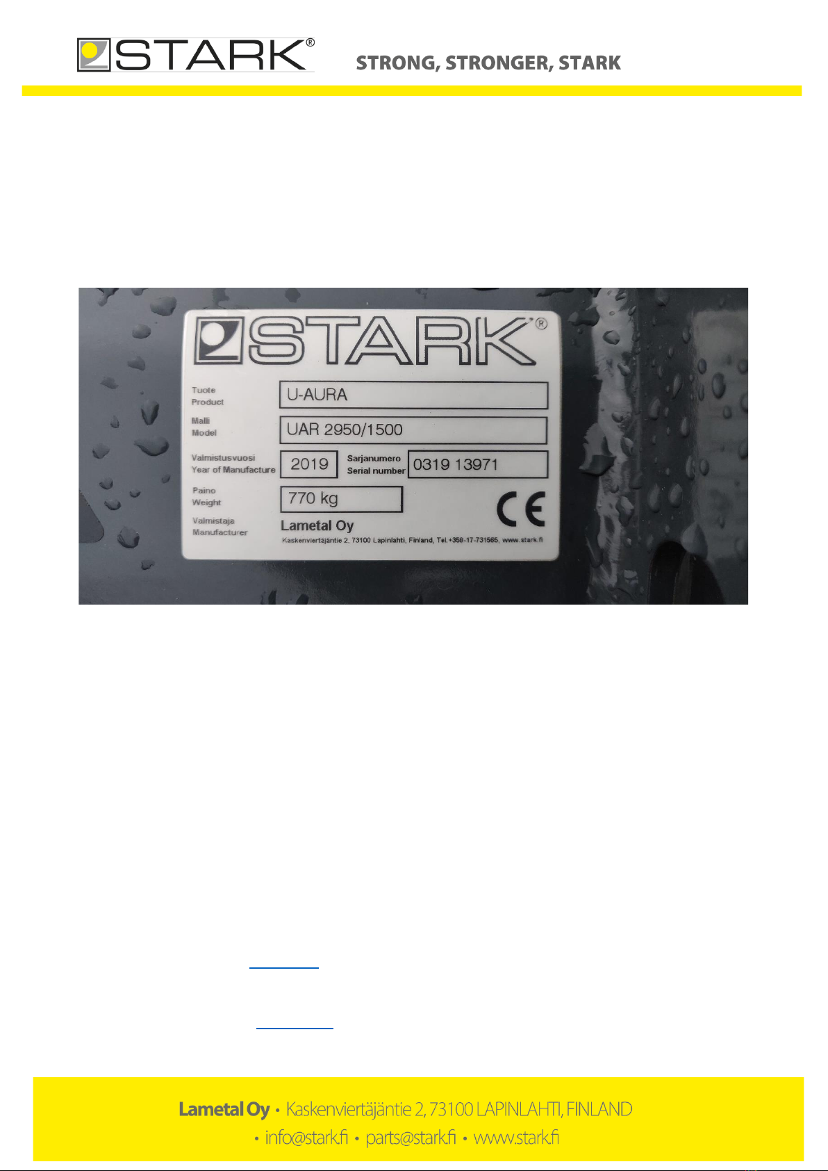
4.1. Identification plate ............................................................................................................................ 6
4.2. Maintenance and parts service ......................................................................................................... 6
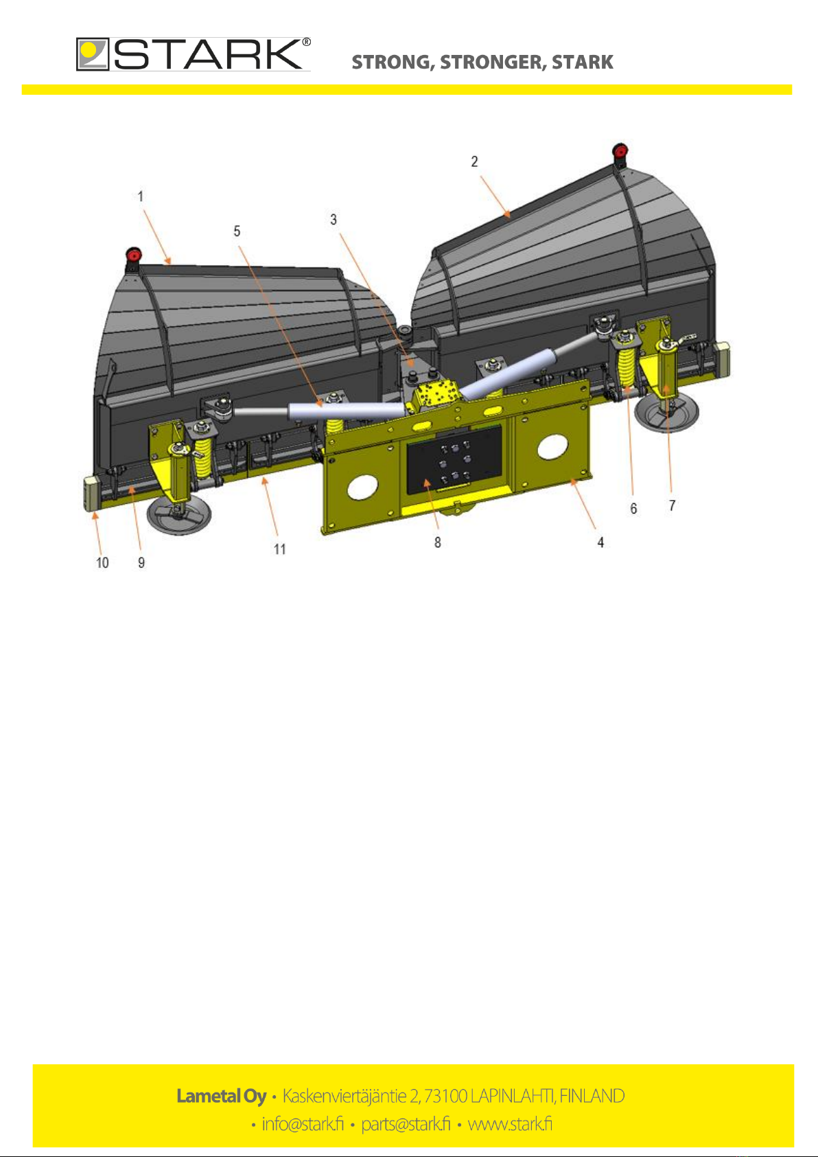
5. MAIN PARTS OF THE PLOW..............................................................................................................7
6. ATTACHING THE PLOW ....................................................................................................................8
6.1. Attaching the plow to a base machine.............................................................................................. 8
7. USING THE PLOW.............................................................................................................................9
7.1. Operating instructions....................................................................................................................... 9
7.2. Permitted driving directions for the plow in different positions .................................................... 10
7.3. Removing packed snow................................................................................................................... 13
7.4. Adjusting RELAX -blade system (NLR-models)................................................................................. 14
7.5. Adjusting ACS (Anti Collision System) -springs (NL-models) ........................................................... 16
7.6. Adjusting flotation........................................................................................................................... 18
7.7. Adjusting support legs..................................................................................................................... 19
7.8. Adjusting blades .............................................................................................................................. 19
7.9. Adjusting perforated blades............................................................................................................ 20
7.10. Adjusting flat blades .................................................................................................................... 21
7.11. Detaching the plow...................................................................................................................... 22
7.12. Transferring the plow .................................................................................................................. 22
7.13. Plow accessories.......................................................................................................................... 22
8. USING AND MAINTAINING.............................................................................................................23
8.1. General cautions concerning use and maintenance of the plow.................................................... 23
8.2. Tightening torque............................................................................................................................ 23
8.3. Daily maintenance........................................................................................................................... 23
8.4. Maintenance after 10 hours............................................................................................................ 23
8.5. Maintenance every 50 hours or weekly.......................................................................................... 23
8.6. Lubrication points............................................................................................................................ 24
9. HYDRAULICS...................................................................................................................................25
9.1. 2- and 3-hose hydraulics.................................................................................................................. 25
9.2. 4- and 5-hose hydraulics.................................................................................................................. 26
9.3. Diagonal valve (3/2 hoses) .............................................................................................................. 27
9.4. Relief valve....................................................................................................................................... 28
10. WARRANTY TERMS AND CONDITIONS ........................................................................................30

Page 4/ 30
1. DECLARATION OF CONFORMITY
Original manufacturer Declaration of conformity:
Product name: Articulated plow
Models: STARK NL 3200, NL 3600, NL 4000, NL 1830R, NL 2440R, NL 2800R, NL 3100R, NL 3300R, NL 3600R,
NL 4000R, NL 2250R
Manufacturer:
Lametal Oy
Kaskenviertäjäntie 2, FIN-73100 LAPINLAHTI
tel. +358 17 731 565
Hereby declare that the following machinery fulfils all the relevant requirements of EC Machinery Directive 2006/42/EC,
and the following standards:
•SFS-EN ISO 12100-1,
•SFS-EN ISO 12100-2
•SFS-EN 1050
The Technical Construction File is maintained at Lametal factory.
The authorized representative located within the Community is:
Lassi Mehtonen
Managing Director
Kaskenviertäjäntie 2
73100 Lapinlahti, FINLAND

Page 5/ 30
2. INTENDED USE
STARK Articulated Plows are designed for plowing and moving snow from yards and streets. Wide turning angles of the
wings ensure articulated plow’s usability in different kinds of areas.
Using to plow or move heavier material than snow is prohibited and will terminate warranty.
3. SAFETY INSTRUCTIONS
Familiarise yourself with the attachment before taking it in use. The plow should be operated only by proficient users.
Before connecting hydraulics to the plow, please check:
-there is no one between the attachment and base machine
-the base machine is turned off and the parking brake is on
When connecting the attachment to base machine, please pay attention:
-that the locking pins and cotter pins are fine
-there is no pressure in the hydraulics system
-that the hydraulic hoses are intact
-when connecting the hydraulics avoid skin contact with hydraulic fluid
-do not pull from the hose, only from the coupling
While operating, please pay attention:
-safe and appropriate speed
-other traffic, people and animals
-danger zones and visual obstacles
-device should not be used when someone is in the danger zone
-be careful around children
-use flashing light while plowing
-do not go under the plow
While servicing the plow, the base machine’s hydraulics must be switched off, the base machine turned off and the
parking brake put on. The plow must be lowered on supports if going under the plow is required. Never go under the
plow if it is not supported.
Daily maintenance:
-check the overall condition of structures, make repairs if needed
-check the condition of hydraulic hoses and couplings, change if damaged
-check the condition of wear blades, adjust or change if needed. See” Adjusting blades”
Maintenance every 50 hours:
-lubricate the lubrication points (locations are given in product specific section)
-check the tightness of the bolts and nuts
Check the tightness of bolts and nuts after first time in use!
If the plow is left unused for a long time, it needs to be cleaned well and lubricated before storage.
BEWARE pressurised hydraulic hoses and components!

Page 6/ 30
4. IDENTIFICATION AND PARTS
4.1. Identification plate
The identification plate can be found on the upper section of the right wing. On the plate can be found the manufacturers
contact info, type and model of the product, manufacturing year, serial number and weight.
The serial number’s first four digits contain the manufacturing month and year (month before year: MMYY). The last five
digits are the actual serial number, which is registered at the manufacturer (example below: 13971). Below a picture of
an identification plate:
Picture 1. Identification plate.
Please write below the product type and serial number of your plow:
Product _________________________________________Serial number_____________________________________
4.2. Maintenance and parts service
Only original parts should be used when making repairs. By using original parts, you can ensure proper operation and
warranty coverage. When inquiring and ordering parts please give the product type and serial number from the
identification plate to facilitate service.
STARK maintenance and parts service as well as your dealer can answer your questions on maintenance and parts.
Please contact your dealer or
STARK maintenance service:
tel. +358 (0)17 731 565, email [email protected]
STARK parts service:
tel. +358 (0)44 758 6221, email parts@stark.fi

Page 7/ 30
5. MAIN PARTS OF THE PLOW
Picture 2. Main parts of the plow
1) Left wing
2) Right wing
3) Turning frame
4) Fitting/flotation frame
5) Hydraulic cylinder
6) Blade frame spring (NL-models) / Blade frame RELAX-spring (NLR-models)
7) Support leg
8) Reflector module
9) Blade frame
10) Side wear blade
11) Wear blade

Page 8/ 30
6. ATTACHING THE PLOW
When attaching the plow for the first time, make sure it is compatible with the base machine by following the instructions
below. Always check the compatibility when attaching the plow to a new base machine.
6.1. Attaching the plow to a base machine
The plow is attached to the base machine by welded or bolted STARK FIT quick hitches. The machine is connected to a
hydraulic system. Hydraulic circuit diagrams can be found in a later section in this manual. Ask your retailer for available
STARK FIT quick hitches.
Before using the plow, MAKE SURE all locking cotters and pins are secured and intact.
When coupling the plow to the base machine, please pay attention to the instructions on the use of the base machine.
1. Make sure that the attachment and the base machine are compatible in terms of mechanical solutions, hydraulics and
electricity.
2. Apply parking brake. The plow is attached to the coupler on the base machine (e.g. a loader). Attach the plow to the
base machine, and make sure the locking cotters and pins are secured.
3. Turn off the base machine and make sure the parking brake is applied.
4. Make sure there is no pressure in the base machine hydraulic system. When connecting, always make sure the
hydraulic connectors are clean and the hoses are intact
5. Check carefully the attachment’s, the base machine’s and the fitting’s trajectory for collision. Do a test run using the
base machine and the loader in extreme position to check that the plow won’t collide with base machine. Make sure that
the hydraulic hoses and attachments have enough space. If needed change the location of hoses in the base machine.
6. During first hours of operating the attachment, bolts, nuts and connectors might loosen up. Retighten them after the
first day of operating the attachment.

Page 9/ 30
7. USING THE PLOW
Before using the plow make sure:
-the plow is installed correctly
-all locking pins are in place
-hydraulic hoses are connected properly
-hoses are intact
-there are no oil leaks
-all functions are working properly
7.1. Operating instructions
1) Make sure that the attachment and the base machine are compatible in terms of mechanical solutions,
hydraulics and electricity
2) The plow is attached to the coupler on the base machine (e.g. a loader). Attach the plow to the base machine,
and make sure the locking cotters and pins are secured.
3) Turn off the base machine and make sure the parking brake is applied.
4) Make sure there is no pressure in the base machine hydraulic system. When connecting, always make sure the
hydraulic connectors are clean and the hoses are intact.
5) Check the attachment’s, the base machine’s and the fitting’s trajectory for collision. Make sure that the hydraulic
hoses and attachments have enough space.
6) Stay alert for any abnormal behavior and oil leaks also during driving. The optimal position for plowing: flotation
in middle position and plow perpendicular to the ground (picture 3).
7) Comply with the applicable laws and regulations when operating the plow.
8) Keep in mind, that rocks and other dangerous objects can be catapulted from the plow when operating. Keep
an appropriate operating speed.
9) In a fast or rough operating loaders support shaft must be used. Stay alert for any abnormal behavior and oil
leaks also during driving.
Picture 3. Optimal position for plowing, flotation in middle position and plow perpendicular to the ground
90°
Flotation in
middle position

Page 10 / 30
7.2. Permitted driving directions for the plow in different positions
Pay attention to the functioning of the relief valve when turning the wings. If plow is driven with the wings in extreme
position, the cylinder piston is at the end of the chamber and the relief valve cannot function. When operating the plow,
leave approx. 20mm of space inside the cylinder, so the relief valve will work as intended (picture 4).
Picture 4. Cylinder piston is at the bottom in extreme positions
Plow with the wings open (picture 5) and close them a little when snow accumulates (picture 6Picture ). Just before
reaching the embankment turn the wings fully upfront (picture 7) to pack the snow and ”lift” the snow on top of the
embankment with the front loader.
NOTE! The plow may be raised to the top position, before reversing tilt the plow towards the embankment (downwards)
to keep the plow in control when lowering it within flotation.
Picture 5. Wings open

Page 11 / 30
Picture 6. Gathering snow
Picture 7. Packing snow

Page 12 / 30
Picture 8. Gathering snow while reversing
NOTE! If the wings are turned back (picture 8) while gathering snow and driving backwards, the RELAX and ACS
systems cannot function. Drive carefully.
When plowing to the side take into account the functionality of the safety valve (picture 9).
Picture 9. Plowing snow to the side

Page 13 / 30
7.3. Removing packed snow
RELAX blade system can be used to remove packed snow. Turn wings straight and tilt the plow slightly forward (picture
10). Push flotation to the bottom, press slightly with the loader and drive slowly forward.
Picture 10. Removing packed snow

Page 14 / 30
7.4. Adjusting RELAX -blade system (NLR-models)
RELAX -release mechanism keeps the blades locked. The plowing result is even and formation of packed snow is
decreased. When the blade hits an obstacle the release mechanism opens allowing the blade frame to turn backwards
and the blade to go over the obstacle. The system protects the driver, the plow and the base machine from damaging.
Plows with RELAX -blade system can be pressed down to remove packed snow.
Operation of the RELAX -blade system
-Blade frame is mechanically locked in position by three joints (picture 11)
-When the blade hits an obstacle, the increased pressure releases the lock and the blade frame swivels in a
quick and wide motion over the obstacle (picture 12)
-When the obstacle is passed, and pressure returns to normal the spring pushes the blade frame back into the
locked position (picture 11)
Picture 11. RELAX -mechanism Picture 12. RELAX -mechanism released
The amount of pressure which releases the lock can be adjusted by changing the angle of the joints (picture 13Picture ).
Larger the angle, the more easily the lock releases. When the adjustment nut is tightened less pressure is required and
when the nut is loosened more pressure is required. The angle between joints should be at least 5° (picture 14) to
enable the release mechanism to function as designed. Never adjust the angle totally straight!
Rigidity of the spring can be adjusted by the tension nut under the spring (picture 15). Shortest permitted length for the
spring is 175 mm when blade is released, then the spring is pre-strained by 25 mm. At the factory the spring is
pre-strained by 15 mm.

Page 15 / 30
Picture 13. RELAX -mechanism minimum angle Picture 14. Minimum α-angle of the joints must be at least 5°
Picture 15. Adjustment of the RELAX -spring
Locking nut
Tension nut

Page 16 / 30
7.5. Adjusting ACS (Anti Collision System) -springs (NL-models)
ACS -blade system of the plow protects the driver, attachment and the base machine from damaging when hitting an
obstacle. Wear blades are bolted to blade frames (picture 16). When hitting an obstacle, the blade frame swivels. ACS -
blade system increases safety but also reduces bouncing of the plow when hitting an obstacle because single blade
frame swivels to pass the obstacle.
Picture 16. Wear blades are bolted to blade frames
Operation of the ACS -blade system
-In normal working position (picture 17) the blade easily digs into an uneven surface
-When hitting an obstacle, the ACS enables the blade frame to swivel backwards (picture 18) and jump over the
obstacle.
Picture 17. Blade in normal position Picture 18. Blade frame swivelling

Page 17 / 30
Rigidity of the blade frame can be adjusted by changing the rigidity of the spring. At the factory the spring is pre-strained
by 15 mm which should not be changed without valid reason. It is possible to change the rigidity of the blade frame by
adding max. 10 mm tension to the spring, the length of the spring will be then min. 275 mm while the blade is in direct
line with the wing. If strained beyond this limit the yield point of the spring will be exceeded when the blade frame
swivels, and the spring will be damaged and is required to replace.
Rigidity of the spring can be adjusted by the pre-straining nuts under the spring (picture 19). By turning the upper nut
anti-clockwise the strain increases and by turning the lower nut it is locked in place. In double spring designs both
springs must be adjusted to same pre-strain. Control the length of the spring during adjusting to avoid exceeding the
minimum length.
The nut on top of the spring does not need to be adjusted. This nut affects the angle of the blade frame with the wing
which has been set in line at the factory. By tightening the nut, the blade frame can be tilted backwards. If adjusting the
angle of the blade frame the length of the spring needs to be controlled not to exceed the limit. Length of the spring
needs to be 275 mm in minimum after all adjustments.
Picture 19. Adjusting the spring
Tension nut
Locking nut
Adjusting blade angle

Page 18 / 30
7.6. Adjusting flotation
U-plows have FLOATING FRAME -flotation system. FLOATING FRAME -technology enables the plow to closely follow
the ground with vertical and horizontal flotation independent from the base machine. FLOATING FRAME -system is
located by the fittings and this location together with the sliding plates reduce bouncing of the plow while working. The
sliding plates need no lubrication.
Adjusting the flotation
1. first tighten the main bolts so that the sliding plates are pressed against the floating frame (main bolts 6 pcs in
picture 20)
2. then tighten also the adjustment bolts all the way to the bottom (adjustment bolts 4 pcs in picture 20)
3. loosen the main bolts only and then tighten the adjustment bolts one round (360°) each
4. then lock this spacing of the sliding plates by tightening the nuts of the adjustment bolts
5. finally tighten the main bolts to torque 404 Nm
6. check the function of the floating frame, the frame should move by hand. Readjust if needed.
➔Do this adjustment anytime the flotation begins to feel too loose while working.
Picture 20. Adjusting flotation
Main bolts
Adjustment
bolts

Page 19 / 30
7.7. Adjusting support legs
Support legs are adjusted by the handle on top (picture 21). By turning the handle clockwise, the support leg will rise and
anti-clockwise it will lower. Normal position can be seen in picture 22 where the support leg is in level with the blade. In
the beginning of the plowing season adjust the support legs a little lower than blade to keep the blade from sinking into
soft ground. Adjust the support legs a little higher than the blade to reduce formation of packed snow.
Picture 21. Adjustment handle of the support leg Picture 22. Correct height of the support leg
7.8. Adjusting blades
Edge of the blade should be 15–45 mm lower than the blade frame. Blades need to be adjusted at the latest when the
blade edge is less than 10 mm lower (picture 23) than the blade frame. Do not adjust the blades more than 50 mm lower
than the blade frame.
Picture 23. Minimum distance of the blade edge from the blade frame
min. 10mm

Page 20 / 30
7.9. Adjusting perforated blades
When adjusting perforated blades, the bolts can be removed by holding the bolt head with locking pliers and loosening
the locking nut behind the blade. Also, when tightening, the bolt head will need to be held to enable the nut to be
tightened. M20 washer is added under the bolt for getting a better grip on it (picture 24).
The bolts are removed, and the blade lowered until a hole on the blade frame can be seen again. The bolts are attached
now to the holes next to the ones they were attached to before (picture 25). This enables the blade to be lowered
appropriately (picture 26).
Picture 24. M20 washer is added under the bolt
Picture 25. The first position of perforated blade
Picture 26. Perforated blade after it has been lowered
This manual suits for next models
10
Table of contents
Other Stark Farm Equipment manuals
Popular Farm Equipment manuals by other brands

CrustBuster
CrustBuster Speed King 10" BeltVeyor owner's manual

Alltech
Alltech KEENAN MechFiber380+ Operator's manual

Yetter
Yetter MAX SEALER PLUS 2920 Series Operator's manual

Alltech
Alltech KEENAN MechFiber400 Operator's manual

Baumalight
Baumalight MS348 Operator's manual

Seppi
Seppi MIDIPIERRE Operating and maintenance manual