manuals.online logo
Brands
  1. Home
  2. •
  3. Brands
  4. •
  5. Staubli
  6. •
  7. Cables And Connectors
  8. •
  9. Staubli Multi-Contact ID/B16BV-NS-A User manual

Staubli Multi-Contact ID/B16BV-NS-A User manual

ill.1
ill.2
ID16BV-WZ
ill.4
ill.3
ill.5
ill.6
ill.7
CHROM - VANADIUM
Fronttafel A
Front panel A
Panneau A
R3,5
56.5
±0.2
max. Ø8
Ø53
±0.2
15 Nm
30Nm
SW17
A/F17
6 pans 17mm
24
17
24
ID/B16BV-NS-A ID/S16BV-NS
MS-ID/S16BV-NS
MS-B16BV-NS
14.0047 14.0040
14.0100 (für/for/pour 14.0040)
14.0102 ( )für/for/pour 14.0047
Mikroschalter
Microswitch
Micro-rupteur
(ill.1)
Torque spanner
17 mm A/F, 15Nm
(ill.1)
Drehmomentschlüssel
SW17, 15Nm
(ill.2)
Steckschlüssel zu Drehmo-
mentschlüssel (ill.1)
ID16BV-WZ,
Bestell-Nr. 14.5019
(ill.2)
Socket wrench for torque
spanner (ill.1) ID16BV-WZ
Order No. 14.5019
(ill.2)
Clé à pipe pour Clé dynamo-
métrique (ill.1) ID16BV-WZ
No. de Cde 14.5019
(ill.1)
Clé dynamométrique
17 mm, 15Nm
(ill.5)
Screwdriver size 2 (required
only for microswitch assem-
bly).
(ill.5)
Schraubendreher Gr. 2 (wird
nur für die Montage des Mi-
kroschalters benötigt).
(ill.5)
Tournevis taille 2 (Seulement
nécessaire pour le montage
d'un micro-rupteur).
(ill.6)
Hammer and punch (max. Ø
8mm) (required only for mi-
croswitch assembly)
(ill.6)
Hammer und Durchschlag Ø
8mm. (wird nur für die Monta-
ge des Mikroschalters benö-
tigt).
(ill.6)
Marteau et poinçon Ø 8mm
(Seulement nécessaire pour
le montage du micro-contact).
(ill.3)
Torque spanner
24 mm A/F, 30Nm
(ill.4)
Open-end spanner 24mm A/F
(ill.3)
Drehmomentschlüssel
SW24, 30Nm
(ill.4)
Gabelschlüssel SW24.
(ill.3)
Clé dynamométrique
24 mm, 30Nm.
(ill.4)
Clé à fourche 24mm
(ill.7)
Drill front panel A according to
drilling plan.
(ill.7)
Fronttafel A gemäss Bohrplan
bohren.
(ill.7)
Percer le panneau A selon le
plan de perçage.
Notwendiges Werkzeug Tools required Outillage nécessaire
1. Connector assembly1. Steckverbinder-
montage
1. Montage du connec-
teur
1/4
MA023 (de_en_fr)
Instructions de montage
MA023 (de_en_fr)
Assembly instructions
MA023 (de_en_fr)
Montageanleitung
Einbaudosen
ID/B16BV-NS-A, ID/S16BV-NS
mit Bajonettverriegelung
Panel receptacle
ID/B16BV-NS-A, ID/S16BV-NS
with bayonet locking
Prises à encastrer
ID/B16BV-NS-A, ID/S16BV-NS
à verrouillage baïonnette
Bond coloured ring (if availa-
ble) to front panel A. Stick the
coloured ring (if present) on
front panel A. The coloured
ring must not be affixed if a
protective cover DE16N
(MA036) is used. In this case
colour coding is effected with
the protective cover.
Den Farbring (wenn vorhan-
den) auf Fronttafel A aufkle-
ben. Bei Montage eines
Schutzdeckels DE16N
(MA036), darf der Farbring
nicht montiert werden. Die
Farbkennzeichnung erfolgt
mit dem Schutzdeckel.
Coller la bague de couleur (si
souhaitée) sur le panneau fron-
tal A. En cas d’utilisation du
couvercle DE16N (MA036),
ne pas monter la bague de cou-
leur. Le repérage couleur sera
réalisé par l’intermédiaire du
couvercle.
I
For protection against electric shock,
parts must be isolated from the power supply
while being assembled or disassembled.
Protection against electric shock has to be
provided in the finished product.
Connectors may not be connected or
disconnected under load.
See the MC-Catalogue for
technical data and assembled parts.
f, during self assembly, parts and tools
other than those stated by MC are used or if the
preparation and assembly instructions
described here are disregarded then neither the
safety nor compliance with the technical data
can be guaranteed.
3 Power
line
Lors de l’assemblage, si des composants
et des outils différents de ceux prescrits par MC
étaient utilisés, si en outre les instructions de
montage ci-après n’étaient pas strictement
appliquées, ni la sécurité, ni la conformité aux
caractéristiques techniques ne sauraient être
garanties.
En vue de garantir une protection contre
les chocs électriques, il est indispensable de
réaliser les opérations de montage et de
démontage hors tension, en veillant à
déconnecter les différents composants de
toute alimentation électrique. La protection
contre les chocs électriques doit être assurée
par le produit fini, à l’état monté.
En règle générale, il ne faut pas embro-
cher ou débrocher un connecteur sous charge.
Caractéristiques techniques et pièces
constituantes: consulter le catalogue MC 3
Power .
line
www.multi-contact.com
Advanced Contact Technology
(cn_en_fr)
ᅝ㺙䇈ᯢ
䴶ᵓᦦᑻ
带卡栓锁紧
೼㞾㸠ᅝ㺙ᯊˈབᵰ᠔⫼ⱘ䚼ӊᎹ
݋ϡᰃMCПࠡ᠔䗄ⱘˈ៪㗙ᗑ⬹њޚ
໛ᅝ㺙᪡԰ˈ៥Ӏᇚϡֱ䆕ѻકᡔ
ᴃϞⱘᅝܼᗻݐᆍᗻDŽ
Ў䰆ℶ⬉ߏˈ䚼ӊ೼ᢚ㺙ᯊˈᖙ乏ᮁ
ᓔ⬉⑤DŽ㒜ッѻકᖙ乏ᦤկ䰆⬉ߏࡳ
㛑DŽ
䖲᥹఼೼䋳䕑ᚙމϟϡ㛑ᮁᓔ៪䖲᥹DŽ
Ⳍ݇ᡔᴃֵᙃᅝ㺙䚼ӊ䇋㾕MCⳂ
ᔩ Powerline
ᖂࡼᓔ݇
᠔䳔Ꮉ݋
ᡁⶽᡇ᠟17mm
A
/F, 15Nm
ᦦᑻᡇ䪇⫼Ѣᡁⶽᡇ᠟(ill.1)
ID16BV-WZˈ䅶䋻ো
14.5019
ᡁⶽᡇ᠟24mmA/F,
30Nm
ᓔষᡇ᠟24mm A/F
㶎ϱ䍋ᄤ ሎᇌ 2˄ҙ⫼Ѣᖂ
ࡼᓔ݇ⱘᅝ㺙˅
䫸ᄤކ༈˄᳔໻Ⳉᕘ8mm˅
˄ҙ⫼Ѣᖂࡼᓔ݇ⱘᅝ㺙˅
前面
板
A
ᅝ㺙䖲᥹఼
ḍ᥂䪏ᄨ೒೼ࠡ䴶ᵓAϞ䪏ᄨDŽ
ᇚ㡆⦃˄བᵰ᳝˅㉬ࠄࠡ䴶ᵓ
A
ϞDŽ㡆⦃ϡ㛑㉬೼ᏆՓ⫼ⱘ
ֱᡸⲪDE16N(MA036)。೼䖭
⾡ᚙމϟˈ⫼买㡆ҷⷕᴹߚ
ֱᡸⲪDŽ
(cn_en_fr) (cn_en_fr)
2/4
4
2
1
A
A33
44
X
5
3
1
2
ill.8
ill.9
ill.10
ill.11
max. 15
(ill.8)
Remove ring nut (4) and P
ring (3) from socket (1) or plug
(2).
UR
(ill.8)
Ringmutter (4) und PUR-Ring
(3) von Buchse (1) bzw. Ste-
cker (2) demontieren.
(ill.8)
Démonter l'écrou cylindrique
(4) et la bague en P de la
douille (1) ou de la broche (2).
UR
(ill.9)
Insert socket (1) or plug (2)
with seal (5) into front panel
(A), making sure that the lugs
on the plug or socket mate
with the opening's slots.
Align socket (1) or plug (2) so
that white triangle is visible
during plugging.
(ill.9)
Buchse (1) bzw. Stecker (2)
mit der Dichtung (5) von vor-
ne in die Fronttafel A stecken
und dabei die Nocken an der
Buchse bzw. am Stecker mit
den Aussparungen in der
Fronttafel ausrichten.
Buchse (1) bzw. Stecker (2)
so ausrichten, dass das weis-
se Markierungsdreieck beim
Steckvorgang gut sichtbar
ist.
(ill.9)
Introduire la douille (1) ou la
broche (2) avec le joint
d'étanchéité (5) dans le pan-
neau A, en veillant à ce que
les ergots de la douille ou de
la broche soient en prise
dans les ouvertures corre-
spondantes du panneau.
Aligner la douille (1) ou la bro-
che (2) de telle façon que le
triangle blanc soit bien visible
au cours de l'embrochage.
(ill.10)
Mount the PUR ring (3) and
the ring nut (4). Arrange the
grooves of the ring nut to-
ward the PUR-ring (see detail
drawing X).
Tighten the ring nut with MC-
socket wrench and with tor-
que spanner .
Tightening torque: 15Nm.
(ill.10)
PUR-Ring (3) und Ringmutter
(4) montieren. Die Rillen der
Ringmutter müssen gegen
den PUR-Ring gerichtet sein
(siehe Detailzeichnung X).
Ringmutter mit MC-Steck-
schlüssel und Drehmo-
mentschlüssel anziehen. An-
zugsdrehmoment:
15Nm.
(ill.10)
Monter la bague en PUR (3) et
l'écrou cylindrique . Veiller à
orienter les stries de l'écrou
cylindrique vers la bague en
PUR (voir le dessin de detail
X). Serrer
vec la clé à pipe et la clé dyna-
mométrique.
Couple de serrage: 15Nm.
(4)
l'écrou cylindrique
a
see separate assembly in-
struction MA036.
siehe separate Montage-
anleitung MA036. voir l’instruction de montage
MA036.
2. Protective cover
assembly
2. Montage des Schutz-
deckels
2. Montage du couver-
cle de protection
3. Installation of micro-
switch
3. Montage des Mikro-
schalters
3. Montage du micro-
rupteur
Note:
With the installated
microswitch the watertight-
ness can not be
guaranteed.
(ill.11)
Break the protection mem-
brane of the through-hole (P)
of the socket (1) or plug (2)
with a punch. Be careful that
the socket resp. the plug is
free from the broken materi-
al.
Hinweis:
Mit montiertem Mikroschal-
ter ist die Wasserdichtheit
(IP65) nicht mehr gewährleis-
tet.
(ill.11)
Schutzhaut am Durchgangs-
loch (P) der Buchse (1) bzw.
des Steckers (2) mit einem
Durchschlag durchbrechen.
Darauf achten, dass sich kein
Durchbruchmaterial im Ste-
cker bzw. in der Buchse be-
findet.
Avis:
Avec le micro-rupteur mon-
té, l’étanchéité n’est plus ga-
rantie.
(ill.11)
Casser la membrane de pro-
tection du trou débouchant
(P) de la douille (1) ou de la
broche (2) à l'aide d'un poin-
çon.
Veiller à ce qu'aucun débris
ne se trouve à l'intérieur de
la douille (1) ou de la broche
(2).
P
P
1
2
www.multi-contact.com
Advanced Contact Technology
ᇚ⦃ᔶ㶎ᐑ4PUR೜3ˈҢᦦ
ᑻ1៪ᦦ༈2ϞপߎDŽ
ᇚᏺᆚᇕ೜ᦦᑻ(1)៪ᦦ༈(2)
ᦦܹ䴶ᵓ(A)ˈ⹂ֱᦦᑻ៪ᦦ
༈Ϟⱘߌ㓬Ϣᓔষⱘ≳ῑ
䜡DŽ
ᇚᦦᑻ(1)៪ᦦ༈(2)ᥦ៤Ⳉ
㒓ˈ೼ᦦܹ䖛⿟Ёⳟࠄⱑ㡆ϝ
㾦ᔶDŽ
ᅝ㺙PUR⦃(3)⦃ᔶ㶎ᐑ
(4)DŽᥦ߫⦃ᔶ㶎ᐑⱘߍῑᇍⴔ
PUR⦃˄䆺㾕೒X˅DŽ⫼MC-
ᦦᑻᡇ䪇ᡁⶽᡇ᠟ᢻ㋻⦃ᔶ
㶎ᐑDŽ
㋻೎ᡁⶽ˖15Nm。
䰆ᡸⲪᅝ㺙
㾕⣀ⱘᅝ㺙䇈ᯢMA036。
ᅝ㺙ᖂࡼᓔ݇
䇈ᯢ˖
⬅Ѣᅝ㺙ᖂࡼᓔ݇ˈ݊∈ᆚᗻ
᮴⊩ֱ䆕DŽ
⫼ކ༈᠇⸈ᦦᑻ(1)៪ᦦ༈(2)
ᄨPϞⱘֱᡸ㝰DŽᇣᖗˈϡ㽕
೼ᦦ༈៪ᦦᑻ㸼䴶⬭ϟล᭭㝰
ⱘ⅟⬭⠽DŽ
U
5a
5b
1
2M3
M3
ill.12
ill.13
ill.14
7 8 9
10
7
7
8
8
9
9
D
D
4. Cable connection 4. Raccordement du
câble
4. Montage der An-
schlussleitung
Functional check of
microswitch
Contrôle du micro-
contact
Funktionskontrolle des
Mikroschalters
(ill.12)
Fasten microswitch (5a) to
socket (1) with the M3
screw. Firmly insert the mi-
croswitch (5a) in the recess
(1) on the socket and fix in
place with the screw (M3).
Fasten microswitch (5b) to-
gether with mounting plate
(U) to the plug (2).
Fimly insert the microswitch
(5b) in the recess (2) on the
plug and fix in place with the
screw (M3).
The microswitch contact is a
changeover contact.
Type of connection: 3 plug
connectors 2.8x0.5, swit-
ching capacity 6A, 250VAC.
(ill.12)
Mikroschalter (5a) auf die
Buchse (1) mit der Schraube
M3 anschrauben. Mikroschal-
ter (5a) auf der Buchse (1) gut
in die Aussparung legen und
mit der Schraube (M3) an-
schrauben.
Mikroschalter (5b) mit Plätt-
chen (U) unterlegt, auf den
Stecker (2) mit der Schraube
M3 anschrauben. Mikroschal-
ter (5b) auf den Stecker (2) gut
in die Aussparung legen und
mit der Schraube (M3) an-
schrauben.
Der Mikroschalter-Kontakt mit
Umschaltkontakt hat 3 Ste-
ckanschlüsse 2.8x0.5 und ei-
ne Schaltleistung von 6A,
250VAC.
Bevor der Mikroschalter auf-
geschraubt wird, muss die
Einbaudose in die Fronttafel
eingebaut werden (siehe ill.7
bis ill.10).
Before fastening the micros-
witch, the panel receptacle
has to be assembled into the
front panel (see ill.7 to ill.10).
Avant de fixer le micro-
rupteur, la prise à encastrer
doit être monté dans le pan-
neau (voir ill.7 jusqu'à ill.10).
(ill.12)
Fixer le micro-rupteur (5a) sur
la douille (1) avec une vis M3.
Pour ce faire, placer correcte-
ment le micro-rupteur (5a)
dans le logement prévu à cet
effet sur la douille (1).
Fixer le micro-rupteur (5b)
avec plaquette de montage
(U) sur la broche (2) avec une
vis M3.
Pour ce faire, placer correcte-
ment le micro-rupteur (5b)
dans le logement prévu à cet
effet sur la broche (2).
Il s'agit d'un micro-rupteur in-
verseur 6A, 250VAC, à trois
contacts 2,8x0,5.
By switching immediately pri-
or to engagement of the inter-
lock, the microswitch indica-
tes that the plug connection is
made.
Important notice:
Correct interlocking is achie-
ved only after engagement.
Le micro-rupteur doit s'en-
clencher avant même que le
verrouillage ne soit réalisé. Il
indiquera ainsi que le contact
est établi.
Remarque importante:
Le verrouillage n'est définiti-
vement réalisé qu'a-près em-
brochage complet des deux
connecteurs.
Der Mikroschalter schaltet un-
mittelbar bevor die Verriege-
lung einrastet und zeigt damit
an, dass die Steckverbindung
hergestellt ist.
Wichtiger Hinweis:
Die korrekte Verriegelung ist
erst nach dem Einrasten si-
chergestellt.
(ill.13)
Remove nut (9), washer (7),
and lock washer (8).
(ill.13)
Mutter (9), Unterlegscheibe
(7) und Federscheibe (8) lö-
sen.
(ill.13)
Démonter l'écrou (9), la ron-
delle (7) et la rondelle éventail
(8).
(ill.14)
Slip cable lug (D) with preas-
sembled cable onto the thre-
ad. Reinstall nut (9), washer
(7) and lock washer (8).
Tighten nut (9) with the torque
spanner 24mm A/F and secu-
re it with nut (10) and the
open-end spanner 24mm A/F.
Tightening torque 30Nm.
(ill.14)
Kabelschuh (D) mit ange-
schlossener Leitung auf das
Gewinde schieben. Unterleg-
scheibe (7), Federscheibe (8)
und Mutter (9) montieren.
Mutter (9) mit Drehmoment-
schlüssel SW24 anziehen
und mit Gabelschlüssel
SW24 und Mutter (10) kon-
tern. Anzugsdrehmoment
30Nm.
(ill.14)
Engager la cosse (D) avec le câ-
ble serti sur l'embout fileté. Re-
monter l'écrou (9), la rondelle
(7) et la rondelle éventail (8). Ser-
rer la cosse avec l'écrou (9) et la
clé dynamométrique 24 mm et
le contre-écrou (10) avec la clé à
fourche 24mm.
Couple de serrage: 30Nm.
3/4
1
C
4
NO
2
NC
www.multi-contact.com
Advanced Contact Technology
೼ࡴ೎ᖂࡼᓔ݇ࠡˈᖙ乏ᇚ䴶
ᵓᦦᑻᅝ㺙ࠄࠡ䴶ᵓϞ˄㾕
ill.7ࠄill.10˅
〇೎ഄᇚᖂࡼᓔ݇(5a)ᦦܹᦦ
ᑻⱘߍῑ˄1˅ˈᑊ⫼㶎ϱ䩝
˄M3˅೎ᅮ݊ԡ㕂DŽ
ᇚᖂࡼᓔ݇˄5b˅ᅝ㺙ᵓ
˄U˅೎ᅮࠄᦦ༈˄2˅Ϟˈ〇
೎ഄᇚᖂࡼᓔ݇˄5b˅ᦦܹᦦ
ᑻⱘߍῑ˄2˅ˈᑊ⫼㶎ϱ䩝
˄M3˅೎ᅮ݊ԡ㕂DŽℸᖂࡼᓔ
݇ⱘ䖲᥹ᰃϾৃ䕀ᤶⱘ䖲᥹DŽ
䖲᥹㉏ൟ˖3Ͼᦦ༈䖲᥹఼
2.8*0.5,ߛᤶᆍ䞣6A,
250VACDŽ
ᖂࡼᓔ݇ࡳ㛑Ẕᶹ
䆒໛ϔᮺᅠ៤ᅝ㺙ˈᖂࡼᓔ݇
ࠏᬍব⢊ᗕˈ߭ᖂࡼᓔ݇ᣛ
⼎ᦦ༈䖲᥹ᅠ៤DŽ
䞡㽕䇈ᯢ˖
া᳝ᦦড়ৢᠡ㛑ᅲ⦄ℷ⹂Ѧ
䫕DŽ
ᅝ㺙⬉㓚
⿏এ㶎ᐑ˄9˅ˈൿ೜˄7˅
䫕㋻ൿ೜˄8˅DŽ
ᇚᏺ乘ᅝ㺙⬉㓚ⱘ⬉㓚䖲᥹⠛
D㺙ࠄ㶎󰶈Ϟˈݡ㺙Ϟ㶎ᐑ
˄9˅ˈൿ೜˄7˅䫕㋻ൿ೜
˄8˅DŽ⫼ᡁⶽᡇ᠟24mmA/F
拧㋻㶎ᐑ˄9˅ˈЎֱ䆕ᅝܼݡ
⫼ᓔষᡇ᠟24mmA/Fࡴ೎㶎ᐑ
(10)DŽ㋻೎ᡁⶽ30NmDŽ
Coding: (...NS series only)
There are a maximum of 6 coding possibili-
ties, designated from
C1 to C6.
The following coding is recommended to
safeguard the interchangeability:
Codage: (uniquement pour la série ...NS)
Il existe jusqu'à 6 possibilités de codage,
identifiées de C1 à C6.
En vue de garantir une parfaite interchan-
geabilité, nous vous recommandons le co-
dage suivant:
Important notice to Plugging and Un-
mating procedure of 16BV connectors:
Caution!
1. Plugging procedure:
1.1.
1.2.
1.3.
Caution!
3.1.
3.2.
- With coding connectors the plugs can on-
ly be inserted into sockets with the same
code no. (inscribed code is next to the whi-
te triangle).
A coded plug though, can be
plugged into an uncoded socket.
This plug connector is equipped with a
bayonet locking system.
the white marks on the male and fema-
le halves must be in line.
Push the two halves together until re-
sistance is met
Press in more deeply and twist to the
right. While twisting, relax the pressure so
that the latch engages automatically after
turning through 90°.
Rotation through more than 90°
in relation to the marked position initiates
the unmating process.
Press in more deeply and then twist to
the left through 90° until the white triangu-
lar marks are in line with each other.
Separate the male and female parts.
2. Test Procedure:
2.1.
2.2.
By twisting the connectors (without
pushing further together), test that the
locking mechanism is engaged.
By attempting to simply pull the
connectors apart, test that the
connection in this position can no longer
be mechanically separated.
3. Unmating:
Remarque importante pour l’embro-
chage et le débrochage des connec-
teurs 16BV:
Attention!
1. Phase d'embrochage:
1.1.
1.2.
1.3.
Attention!
2. Contrôle:
3. Phase de débrochage:
3.1.
3.2.
- Une broche codée ne pourra pas être con-
necteé à une douille avec un codage diffé-
rent (les No. de codage sont apposés à co-
té des triangles blancs)
Une broche codée peut se con-
necter à une douille non codée.
Ces connecteurs sont équipés d'un
système de verrouillage à baïonnette.
Il faut aligner les marquages blancs du
côté broche et du côté douille.
Connecter les deux parties jusqu’en
butée.
Pousser axialement tout en imprimant
un mouvement de rotation vers la droite.
Relâcher la pression axiale. Le verrouillage
s’enclenche automatiquement après une
rotation de 90°.
Une rotation de plus de 90° par
rapport au marquage amorce de nouveau
le débrochage.
Pousser l'une des deux parties dans
l'axe, tout en lui imprimant un mouvement
de rotation de 90° vers la gauche ou la droi-
te, de sorte à aligner les triangles blancs
(apposés sur les deux parties) sur un mê-
me axe.
Retirer la broche de la douille.
2.1. Vérifier en tournant (sans pousser)
que le verrouillage est enclenché.
Vérifier en tirant que la liaison
ne peut plus être séparée mécanique-
ment dans cette position.
2.2.
Kodierung: (Nur ...NS Typen)
Es gibt max. 6 Kodiermöglichkeiten, ge-
kennzeichnet mit C1 bis C6.
Folgende Kodierzuordnung wird zur Si-
cherstellung der Auswechselbarkeit emp-
fohlen:
Wichtige Hinweise zum Steck- und
Trennvorgang der Steckverbindung
16BV:
2.1.
2.2.
3.1.
3.2.
- bei kodierten Steckverbindungen sind
nur Stecker mit Buchsen steckbar, die die
gleiche Kodier-Nr. aufweisen. (Eingeprägt
unmittelbar beim weissen Dreieck).
Achtung!
Durch eine Drehbewegung (ohne Tie-
ferstecken) prüfen ob die Verriegelung im
Eingriff ist.
Durch Zug prüfen, ob die Verbindung
in dieser Position mechanisch nicht mehr
getrennt werden kann.
Die Steckverbindung axial tieferste-
cken, und gleichzeitig um 90° nach links
drehen, bis sich die weissen Markierun-
gen axial gegenüberstehen.
Stecker und Buchse trennen.
Ein kodierter Stecker kann aber
mit einer unkodierten Buchse gesteckt
werden.
Die Steckverbindung ist mit einer Bajo-
nettverriegelung ausgerüstet.
Weisse Markierungen von Stecker-
seite und Buchsenseite müssen axial ge-
genüberstehen.
Steckverbindung bis zum Anschlag zu-
sammenstecken
Mit axialem Druck tieferstecken und
gleichzeitig die Drehung nach rechts ein-
leiten. Während der Drehung den axialen
Druck wieder lösen, sodass nach 90° die
Verriegelung selbständig einrastet.
Bei einer Drehbewegung von
mehr als 90° wird der Trennvorgang wie-
der eingeleitet.
1. Steckvorgang:
1.1.
1.2.
1.3.
Vorsicht!
2. Prüfvorgang:
3. Trennvorgang:
4/4
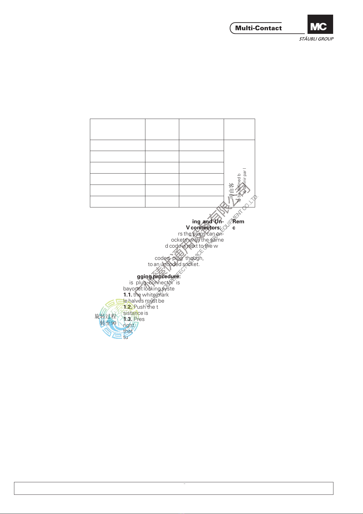
Bezeichnung Symbol Kodier-Nr. Farbe
Designation Symbol Coding-No. Colour
Désignation Symbole No de codage Couleur
Phase 1 L1 C1
Phase 2 L2 C2
Phase 3 L3 C3
Neutral/neutre N C4
Erde/ground/terre PE C5
--C6
Durch Kunden festzulegen
To be defined by the customer
A définir par le client
MA023 (de_en_fr) Änderungen vorbehalten / Subject to alterations / Modifications sous réserve
Copyright by Multi-Contact AG, Switzerland / / 07.2010 / Index gPower
line
www.multi-contact.com
Advanced Contact Technology
编
码:(...仅用于NS系列)
᳔໮6⾡㓪ⷕˈৡ⿄ҢC1ࠄC6。
ϟ߫㓪ⷕ㹿᥼㤤⫼ҹᅝܼѦᤶ
名称
符
号编码 颜
色
相
1
相
2
相
3
中线
接地
ৃ⬅ᅶ᠋ᣛᅮ
cn_en_fr 保留修
改
权利
ᇍѢ%9䖲᥹఼ᦦܹᢨߎ⿟ᑣⱘ䞡㽕ᦤ
⼎˖
ᏺ㓪ⷕⱘ䖲᥹఼ᦦ༈া㛑ᦦܹᏺⳌৠ㓪ⷕ
োⱘᦦᑻᣛ⼎㓪ⷕ೼ⱑ㡆ϝ㾦ⱘᮕ䖍
⊼ᛣʽᏺ㓪ⷕⱘᦦ༈ৃҹᦦܹϡᏺ㓪ⷕⱘ
ᦦᑻDŽ
ᦦܹ⿟ᑣ˖
ℸᦦ༈䖲᥹఼ᏺ󰶈䫕㋻㋏㒳DŽ
ᦦ༈ᦦᑻϞⱘⱑ㡆󰵼䆄ᖙ乏ᇍ唤
ᇚᦦ༈ᦦᑻ᥼೼ϔ䍋Ⳉ㟇ᅠܼ䌈ড়
㒻㓁৥䞠᥼䖯ᑊ৥েᮟ䕀DŽ೼ᮟ䕀䖛⿟
Ёذℶᮑࡴ࡯ˈ󰶈䫕㋻㺙㕂೼ᮟ䕀㟇
ᑺᯊӮ㞾ࡼ䫕㋻ୂড়DŽ
⊼ᛣ˖䕀䖛󰵼䆄ԡ㕂䍙䖛ᑺᯊӮᓩ䍋ϡ㛑
䫕㋻ⱘᚙމDŽ
⌟䆩⿟ᑣ˖
ᮟ䕀䖲᥹఼ϡ㒻㓁᥼䖯⹂䅸󰶈䫕
㋻㋏㒳Ꮖ㒣䫕㋻ୂড়DŽ
ᇱ䆩ᢨᓔ䖲᥹఼ˈ⹂䅸䖲᥹఼ϡ㛑㹿
ᴎẄഄᢨᓔߚ⾏DŽ
ᢨߎ⿟ᑣ˖
ᇚᦦ༈᥼ܹϔѯˈৠᯊ৥Ꮊᮟ䕀
ᑺˈⳈࠄⱑ㡆ϝ㾦ᔶ󰵼䆄ᇍ唤DŽ
ᢨᓔᦦ༈ᦦᑻDŽ

This manual suits for next models

1

Other Staubli Cables And Connectors manuals

Staubli PV-SSH4 User manual

Staubli

Staubli PV-SSH4 User manual

Staubli PV-KST4 UR Series User manual

Staubli

Staubli PV-KST4 UR Series User manual

Staubli PV-JB/WL-V User manual

Staubli

Staubli PV-JB/WL-V User manual

Staubli MA273 User manual

Staubli

Staubli MA273 User manual

Staubli CombiTac MA213-03 User manual

Staubli

Staubli CombiTac MA213-03 User manual

Staubli 16BL-PP User manual

Staubli

Staubli 16BL-PP User manual

Staubli MA084 User manual

Staubli

Staubli MA084 User manual

Staubli PV-KST4 UR Series User manual

Staubli

Staubli PV-KST4 UR Series User manual

Staubli CombiTac User manual

Staubli

Staubli CombiTac User manual

Staubli CombiTac MA213-09 User manual

Staubli

Staubli CombiTac MA213-09 User manual

Staubli KST10BV-AX/M C Series User manual

Staubli

Staubli KST10BV-AX/M C Series User manual

Staubli PV-KST4 UR Series User manual

Staubli

Staubli PV-KST4 UR Series User manual

Staubli MC4-Evo 2 User manual

Staubli

Staubli MC4-Evo 2 User manual

Staubli PV-KBT4-EVO 2-UR User manual

Staubli

Staubli PV-KBT4-EVO 2-UR User manual

Staubli M220 User manual

Staubli

Staubli M220 User manual

Staubli MC4-Evo 2 User manual

Staubli

Staubli MC4-Evo 2 User manual

Staubli CombiTac MA213-06 User manual

Staubli

Staubli CombiTac MA213-06 User manual

Staubli MA046 User manual

Staubli

Staubli MA046 User manual

Staubli CombiTac User manual

Staubli

Staubli CombiTac User manual

Staubli PV-AZS4 User manual

Staubli

Staubli PV-AZS4 User manual

Staubli MC4-Evo 2 User manual

Staubli

Staubli MC4-Evo 2 User manual

Staubli MA231 User manual

Staubli

Staubli MA231 User manual

Staubli RobiFix User manual

Staubli

Staubli RobiFix User manual

Staubli DuraDock power 550 A User manual

Staubli

Staubli DuraDock power 550 A User manual

Popular Cables And Connectors manuals by other brands

Bosch B99 installation manual

Bosch

Bosch B99 installation manual

DEFA MiniPlug User's installation guide

DEFA

DEFA MiniPlug User's installation guide

Lindy 43098 user manual

Lindy

Lindy 43098 user manual

ELCART 42/12490-00 user manual

ELCART

ELCART 42/12490-00 user manual

National Instruments 9212 CALIBRATION PROCEDURE

National Instruments

National Instruments 9212 CALIBRATION PROCEDURE

ClickTronic active HDMI manual

ClickTronic

ClickTronic active HDMI manual

LIN 43265 user manual

LIN

LIN 43265 user manual

Icom OPC-2350LU instructions

Icom

Icom OPC-2350LU instructions

PCB Piezotronics 010G25 Installation and operating manual

PCB Piezotronics

PCB Piezotronics 010G25 Installation and operating manual

SC&T GL001HP user manual

SC&T

SC&T GL001HP user manual

Hitachi H8S/2212 Series user manual

Hitachi

Hitachi H8S/2212 Series user manual

CONNECTGO CG049M manual

CONNECTGO

CONNECTGO CG049M manual

KVM Discovery SP-116R user manual

KVM Discovery

KVM Discovery SP-116R user manual

CommScope FOSC 450 A Installation instruction

CommScope

CommScope FOSC 450 A Installation instruction

Philips MWS2823T Specifications

Philips

Philips MWS2823T Specifications

National Instruments IMAQ A8055 installation guide

National Instruments

National Instruments IMAQ A8055 installation guide

Multi-Contact FL3-SG-24+PE/ PA Series Assembly instructions

Multi-Contact

Multi-Contact FL3-SG-24+PE/ PA Series Assembly instructions

Toslink 1x2 S/PDIF Quick installation guide

Toslink

Toslink 1x2 S/PDIF Quick installation guide

manuals.online logo
manuals.online logoBrands
  • About & Mission
  • Contact us
  • Privacy Policy
  • Terms and Conditions

Copyright 2025 Manuals.Online. All Rights Reserved.