manuals.online logo
Brands
  1. Home
  2. •
  3. Brands
  4. •
  5. Staubli
  6. •
  7. Cables And Connectors
  8. •
  9. Staubli MA417-1 User manual

Staubli MA417-1 User manual

1 / 24
CTD-NET Coax 1.5 GHz
Coax 2.4 GHz
Coax SMA 6 GHz RJ45
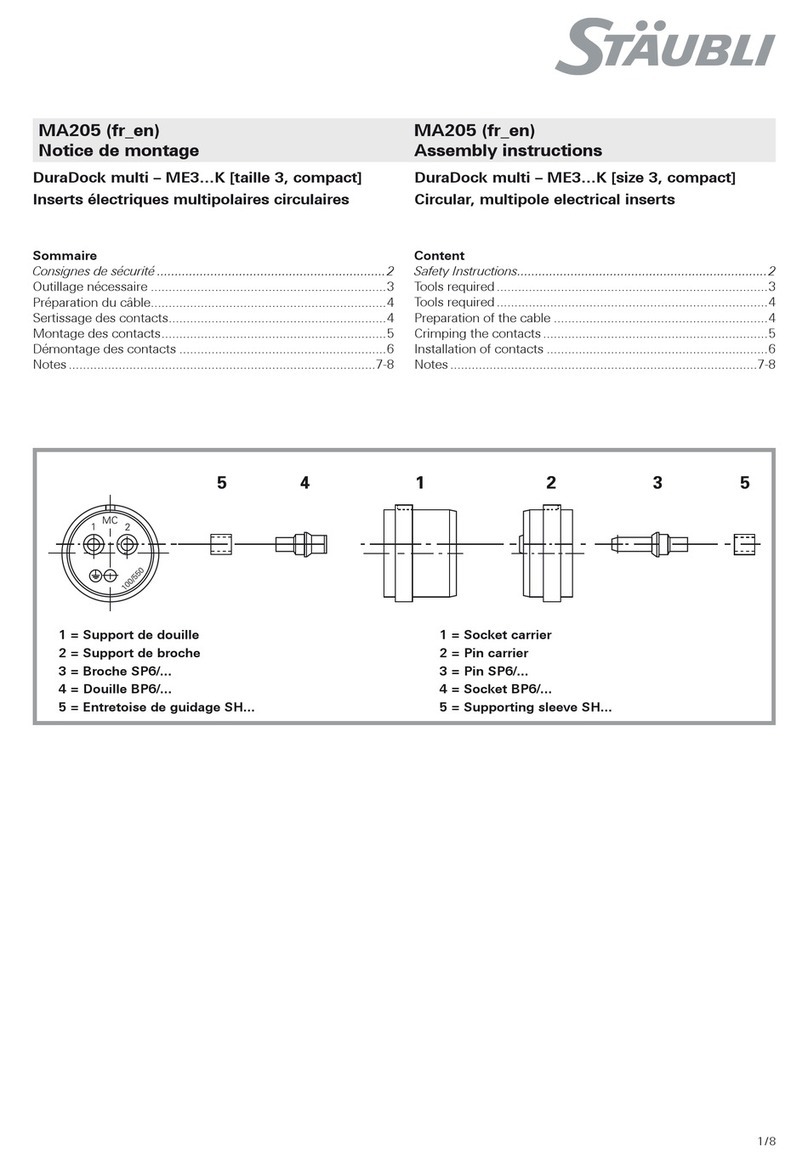
MA417-1 (es_en)
Instrucciones de montaje
Índice
Instrucciones de seguridad����������������������������������������������������������2
Módulo 1 Gbit CTD-NET......................................................4 – 10
RJ45 .........................................................................................11
Módulo coaxial RG58 1,5 GHz ..........................................12 – 14
Módulo coaxial RG316/RG58 2.4 GHz ..............................15 – 20
SMA coaxial 6 GHz ...........................................................21 – 22
Inserción del portador en el marco.............................................23
Extracción del portador del marco .............................................24
CombiTac direqt
Módulos de datos
MA417-1 (es_en)
Assembly instructions
CombiTac direqt
Data Module
Content
Safety Instructions �����������������������������������������������������������������������2
1 Gbit module CTD-NET......................................................4 – 10
RJ45 .........................................................................................11
Coaxial module RG58 1.5 GHz..........................................12 – 14
Coaxial module RG316/RG58 2.4 GHz .............................15 – 20
Coaxial SMA 6 GHz...........................................................21 – 22
Insertion of carrier in frame.........................................................23
Removing of carrier from frame..................................................24
2 / 24 MA417-1
Instrucciones de seguridad Safety instructions
Use solo los componentes y las herramientas que especifica
Stäubli. Si realiza usted mismo el montaje, siga todas las ins-
trucciones de preparación y montaje tal y como se especifican
aquí. De lo contrario, Stäubli no puede garantizar la seguridad ni
la conformidad con los datos técnicos. No modifique el producto
de ninguna forma.
Use only the components and tools specified by Stäubli. In
case of self-assembly, do not deviate from the preparation and
assembly instructions as stated herein, otherwise Stäubli cannot
give any guarantee as to safety or conformity with the technical
data. Do not modify the product in any way.
Los conectores no fabricados por Stäubli, que pueden acoplarse
a elementos de Stäubli y que en algunos casos los fabricantes
incluso describen como «compatibles con Stäubli» no cumplen
con los requisitos de conexión eléctrica segura con estabilidad a
largo plazo y, por motivos de seguridad, no deben conectarse a
elementos de Stäubli. Por lo tanto, Stäubli no se responsabiliza-
rá si se producen daños como consecuencia de acoplar dichos
conectores (es decir, que no tengan la aprobación de Stäubli) a
elementos de Stäubli.
Connectors not originally manufactured by Stäubli which can be
mated with Stäubli elements and in some cases are even de-
scribed as ”Stäubli-compatible” by certain manufacturers do not
conform to the requirements for safe electrical connection with
long-term stability, and for safety reasons must not be plugged
together with Stäubli elements. Stäubli therefore does not
accept any liability for any damages resulting from mating such
connectors (i.e. lacking Stäubli approval) with Stäubli elements.
Stäubli Electrical Connectors (Stäubli) no se responsabilizará en
caso de que no se cumpla con estas advertencias.
Stäubli Electrical Connectors (Stäubli) does not accept any
liability in the event of failure to observe these warnings.
IEC 60417-6182
Instalación, conocimientos electrotécnicos Installation, electro technical expertise
Los individuos que pueden montar e instalar estos productos son
personas capacitadas o con conocimientos en electricidad que
deben cumplir con todas las normas de seguridad pertinentes.
The products may be assembled and installed by electrically
skilled or instructed persons duly observing all applicable safety
regulations.
IEC 60417-6042
Precaución, riesgo de descarga eléctrica Caution, risk of electric shock
Trabaje sin electricidad
Al trabajar en instalaciones eléctricas, siga las cinco reglas de
seguridad.
Tras identificar las respectivas instalaciones eléctricas, deben
seguirse los siguientes cinco requisitos esenciales en el orden
especificado, a menos que haya razones importantes para no
hacerlo:
•desconectar completamente;
•asegurarse de que no se produzca una reconexión;
•verificar la ausencia de voltaje operativo;
•realizar puesta a tierra y cortocircuito;
•proporcionar protección contra las piezas conductoras adya-
centes.
Cualquier persona que realice esta actividad debe estar capaci-
tada o debe poseer conocimientos en electricidad. De lo contra-
rio, debe hacerla bajo la supervisión de una que sí esté capacita-
da o cuente con dichos conocimientos.
Fuente: EN 50110-1:2013
Work in a de-energized state
Follow the five safety rules, when working on electrical installa-
tions.
After the respective electrical installations have been identified,
the following five essential requirements shall be undertaken in
the specified order unless there are essential reasons for doing
otherwise:
•disconnect completely;
•secure against re-connection;
•verify absence of operating voltage;
•carry out grounding and short-circuiting;
•provide protection against adjacent live parts.
Any person engaged in this work activity shall be electrically
skilled or instructed, or shall be supervised by such a person.
Source: EN 50110-1:2013
La protección contra descargas eléctricas también se debe veri-
ficar en las aplicaciones finales.
Protection against electric shock shall be checked in the end-use
applications too.
IEC 60417-6070
No conectar y desconectar bajo carga Do not connect and disconnect under load
La conexión y desconexión bajo tensión solo está permitida si la
tensión nominal no supera los 1000 V CA/1500 V CC .
Para tensiones nominales superiores a 1000 V CA/1500 V CC,
la tensión solo debe aplicarse en estado acoplado, desconectar
bajo carga
o conectar bajo tensión no está permitido. Esto también se apli-
ca a las conexiones eléctricas que se encuentran cerca de las
conexiones de fluidos y gases.
Connecting and disconnecting when live is only permitted if the
rated voltage does not exceed AC 1000 V/DC 1500 V .
For rated voltages over AC 1000 V/DC 1500 V, the voltage must
only be applied in mated condition, disconnecting under load
or connecting when live is not permitted. This also applies for
electrical connections in close proximity to fluid and gas con-
nections.
MA417-1 3 / 24
Instrucciones de seguridad Safety instructions
ISO 7000-0434B
Precaución Caution
Cada vez que se use el conector, se debe inspeccionar previa-
mente si hay defectos externos (particularmente el aislamiento).
Si hay problemas de seguridad, debe consultarse a una persona
con conocimientos en electricidad o reemplazarse el conector.
Each time the connector is used, it should previously be inspect-
ed for external defects (particularly the insulation). If there are any
safety concerns, an electrically skilled person must be consulted
or the connector must be replaced.
Protección IP según 60529:2013 IP protection according to 60529:2013
Los conectores no acoplado debe protegerse contra la humedad
y el polvo. Las partes macho y hembra no deben conectarse
cuando estén sucias.
Unmated plug connectors must be protected from moisture and
dirt. The male and female parts must not be plugged together
when soiled.
Examinar; comprobar Examine; Check
Señalar el examen o la comprobación To indicate examination or checking
Consejo útil Useful hint or tip
Para obtener más datos técnicos, consulte el catálogo de pro-
ductos.
For further technical data please see the product catalog.
4 / 24 MA417-1
1245
6
3
6542
1
3
Módulo 1 Gbit CTD-NET
Pos. Descripción/Description
1 Portador para módulo/Module carrier
2 Contacto pantalla macho/Pin body
3 Clip de retención/Retaining clip
4 Portacontactos/Contact carrier
5 Anillo de fijación/Clamp ring
6 Tuerca/Nut
Pos. Descripción/Description
1 Portador para módulo/Module carrier
2 Contacto pantalla hembra/Socket body
3 Clip de retención/Retaining clip
4 Portacontactos/Contact carrier
5 Anillo de fijación/Clamp ring
6 Tuerca/Nut
Lado hembra Lado macho
1 Gbit module CTD-NET
Socket side Pin side
MA417-1 5 / 24
1
2
3
4
(fig. 4)
Destornillador
Tamaño 2 y 3
(para reparar/retirar los portadores del
bastidor).
(fig. 3)
Cinta de conducción CU para módulos
de 1 Gbit, n.º de pedido 11012526.
(fig. 2)
Herramientas de extracción
CT-NET-AWZ, N.º de pedido 33.3048
(Solo para fines de reparación).
Nota:
Instrucciones de funcionamiento
MA079, www.staubli.com/electrical
o
Crimpadoras CT-M-CZ
N.º de pedido 33.3800
y posicionador MES-CZ,
N.º de pedido 18.3801
Nota:
Instrucciones de funcionamiento
MA419, www.staubli.com/electrical
(fig. 1)
Crimpadoras CTD-M-CZ
N.º de pedido 33.3900
y posicionador MES-CZ-CTD1NET,
N.º de pedido 33.3913
Herramientas necesarias Tools required
(ill. 1)
Crimping pliers CTD-M-CZ
Order No. 33.3900
and locator MES-CZ-CTD1NET,
Order No. 33.3913
Note:
Operating instructions MA419,
www.staubli.com/electrical
or
Crimping pliers CT-M-CZ
Order No. 33.3800
and locator MES-CZ,
Order No. 18.3801
Note:
Operating instructions MA079,
www.staubli.com/electrical
(ill. 2)
Extraction tool
CT-NET-AWZ, order No. 33.3048
(For repair purposes only).
(ill. 3)
CU conductive tape for 1 Gbit
moduls, order No. 11012526.
(ill. 4)
Screwdriver
Size 2 and 3
(for repair/removal of carriers from
frame).
6 / 24 MA417-1
6
4,5
5
Tabla 1/Tab. 1
Pasos
Steps Cable 1 Cable 2
1
18 18
2
33.1 3.2 3.3
4
(fig. 6)
Despliegue los distintos cables y pélelos
a 4,5 mm.
(Tabla 1)
Sin dañar la protección, retire con cuidado 18 mm del aislamiento
del cable exterior.
•Para el cable de tipo 1, tire de los cables de protección hacia
atrás sobre el cable de aislamiento exterior y asegúrelos con 2
vueltas de cinta conductora.
•Para el cable de tipo 2, corte el papel de protección. Aplique
una vuelta de cinta conductora sobre el aislamiento exterior
(3.1). Tire hacia atrás del cable de drenaje sobre la cinta de
conducción (3.2) y finalmente asegure el cable de drenaje con 2
vueltas de cinta de conducción (3.3).
(fig. 5)
Deslice la tuerca My el anillo de suje-
ción Zen la secuencia indicada en el
cable.
Diámetro del cable:
mín. 5,5 mm
máx. 7,5 mm
Preparación del cable Cable preparation
(ill. 5)
Slip nut Mand clamp ring Zin the indi-
cated sequence onto the cable.
Cable diameter:
Min. 5.5mm
Max. 7.5mm
(Tab. 1)
Without damaging the shielding, carefully strip 18 mm of outer
cable insulation.
•For type 1 cable, pull the shield wires back over the outer insu-
lation cable and secure with 2 turns of conductive tape.
•For type 2 cable, cut o the shield paper. Place one turn of
conductive tape over outer insulation (3.1). Pull back the drain
wire over the conductive tape (3.2) and finally secure the drain
wire with 2 turns of conductive tape (3.3).
(ill. 6)
Fan out single wires and strip them to
4.5mm.
MA417-1 7 / 24
7
8
B
S
9
Orificio de inspección
(fig. 9)
El inserto hembra está marcado con
una B, el inserto macho está marcado
con una S.
Los números del contacto se encuen-
tran en la parte trasera.
Los contactos se introducen por la
parte trasera.
Tabla 2/Tab. 2
Sección transversal del conductor
Conductor cross section Posición del selector
Selector position
mm² AWG
0.14 26 1
0.25 24 2
0.34 22 3
0.51) 20 4
0.751) 18 5
1) Máximo cuatro cables por conector
1) Maximal four wires per connector
(fig. 8)
Consulte la tabla 2 para la posición
del selector según la sección del con-
ductor.
(contactos con un Ø de1, 1,5y
3mm)
Nota:
Los cables introducidos deben que-
dar visibles en el orificio de inspec-
ción antes y después del engastado.
(fig. 7)
Introduzca el cable en el manguito de
engastado hasta el tope.
Crimpado Crimping
(ill. 7)
Insert wire into the crimping sleeve as
far as it will go.
(Ø 1 mm, 1.5 mm, 3 mm contacts)
Note:
Wire must be visible in the sight hole
before and after crimping.
(ill. 8)
See Tab. 2 for selector position
according to conductor cross section.
(ill. 9)
The female insert is marked with a B,
the pin insert is marked with an S.
The contact numbers are on the back
side.
The contacts will be inserted from back
side.
Sight hole
8 / 24 MA417-1
10
Ethernet/Profinet
CAT5
CAT5e
Interbus
Profibus
Ethernet/Profinet
11
Interbus
DO 1
/DO 2
DI 3
/DI 6
COM 4
Profibus
Línea A/
Line A 1
Línea B/
Line B 2
GND 4
Ethernet 100 MBit & Profinet
TX+ 1
TX- 2
RX+ 3
RX- 6
CANbus
Configuración individual según las
especificaciones del BUS
Individual configuration according to
BUS specifications
Lado macho Lado hembra
Atención
Las cámaras de contacto no usa-
das deben cerrarse con tapones
ciegos CT-NET-BS, n.º de pedido
33.9589
(fig. 11)
Introduzca los contactos por en el lado
y el número indicados hasta que que-
den encajados.
Tabla 4/Tab. 4
N.º de contacto
Contact No.
N.º de par
Pair No. Color Colour
1 1 blanco/naranja white/orange
2 1 naranja orange
3 2 blanco/verde white/green
4 3 azul blue
5 3 blanco/azul white/blue
6 2 verde green
7 4 blanco/marrón white/brown
8 4 marrón brown
Configuración de Ethernet y Profi-
net hasta 1 GBit con 4 pares T568B
Tabla 3/Tab. 3
N.º de contacto
Contact No.
N.º de par
Pair No. Color Colour
1 1 blanco/verde white/green
2 1 verde green
3 2 blanco/naranja white/orange
4 3 azul blue
5 3 blanco/azul white/blue
6 2 naranja orange
7 4 blanco/marrón white/brown
8 4 marrón brown
Configuración de Ethernet y Profi-
net hasta 1 GBit con 4 pares T568A
(fig. 10)
(Vista desde el lado de la terminación)
Disposición de los contactos del portacontactos Contact arrangement of the contact carrier
(ill. 10)
(Seen from the termination side)
Ethernet & Profinet up to 1 GBit
configuration with 4 pairs T568A
Ethernet & Profinet up to 1 GBit
configuration with 4 pairs T568B
(ill. 11)
Push the contacts through the number
indicated side until they lock into place.
Attention
Unused contact chambers should
be closed with blind plugs
CT-NET-BS, order No. 33.9589
Pin side Socket side
MA417-1 9 / 24
12
A
13
B
C
D
14
MB
15
M
•Compruebe que los contactos estén bien insertados en el por-
tador tirando suavemente del cable.
Atención
Después de crimpar y montar en los portacontactos, y
antes de la primera conexión, compruebe que los contactos
macho no están dañadas (dobladas, rotas...)
Atención
Apriete la tuerca solo a mano (sin herramienta). La cantidad
de rosca que queda visible después de apretar la tuerca
depende del diámetro exterior del cable.
(fig. 15)
•Inserte toda la unidad en el portacontactos.
Asegúrese de que la posición de la parte plana es correcta.
•Apriete la tuerca Mmientras sujeta el cable para evitar cual-
quier rotación del mismo.
(fig. 14)
•Introduzca la tuerca Msobre el anillo de fijación B.
(fig. 13)
Conecte el anillo de fijación Bal portacontactos C.
Coloque la parte delantera Dsobre la zona plana del portacon-
tactos C.
(fig. 12)
Monte el clip de retención Aen la ranura del cuerpo del contacto
macho e introduzca todo en el portacontactos.
Se escucha un sonido de “clic” una vez que se inserta completamente.
Nota:
Consulte las páginas 23 – 24 para la correcta inserción
y extracción del soporte en el marco.
Montaje en portacontactos
Nota:
Si el soporte universal se utiliza en combinación con la
carcasa de tamaño 4 con entrada de cable lateral, por ejemplo,
CT-CH4-S (Nº de pedido 33.2404), póngase en contacto con
nosotros para obtener más información.
Assembly in contact carrier
Note:
Please refer to pages 23 – 24 for correct insertion and
removing of carrier in frame.
(ill. 12)
Mount retaining clip Ain the groove of the pin body and push
everything into contact carrier.
A “click” sound is heard once fully inserted.
(ill. 13)
Connect the clamp ring Bto the contact carrier C.
Place the leading part Dover the flat area of the contact
carrier C.
(ill. 14)
•Push nut Mover the clamp ring B.
(ill. 15)
•Insert the whole unit in the contact carrier.
Ensure that the position of the flat part is correct.
•Tighten nut Mwhile holding the cable to avoid any cable rota-
tion.
Attention
Tighten the nut only by hand (without tool). The amount of
thread that is visible after tightening the nut depends on the
outside diameter of the cable.
Attention
After crimping and assembly into the contact carriers, and
before first connection, check that the plugs are not dam-
aged (bent, broken…)
•Check that contacts are securely inserted in the carrier by gen-
tly pulling the cable.
Clic
Note:
If the universal carrier is used in combination with the size4
housing with side cable entry, for example CT-CH4-S (Order
No. 33.2404), please contact us for clarification.
10 / 24 MA417-1
17
CT-NET-AWZ D
16
1
2
3
4
(fig. 17)
•Introduzca la herramienta de extrac-
ción CT-NET-AWZ por la parte delan-
tera en el inserto de contacto hasta
que oiga un clic.
•A continuación, con la deriva Dem-
puje hacia fuera el contacto.
Extracción de los contactos
(fig. 16)
1. Aplique una ligera fuerza continua
sobre el tubo CT-Net.
2. Utilice el destornillador para presionar
el primer clip.
3. Presione el segundo clip con el
destornillador.
4. Extraiga el inserto de contacto
Extracción de CTD-NET del
portador
Extraction of CTD-NET from
carrier
(ill. 16)
1. Apply a slight continuous force on
the CT-Net tube.
2. Use the screwdriver to press the first
clip.
3. Press the second clip with the
screwdriver.
4. Pull out the contact insert
Extraction of contacts
(ill. 17)
•Insert the extraction tool CT-NET-AWZ
from the front side into the contact
insert until you hear a click.
•Then with the drift Dpush out the
contact.
MA417-1 11 / 24
RJ45
Lado hembra Lado macho
Nota:
Consulte las páginas 23 – 24 para la correcta inserción
y extracción del soporte en el marco.
Nota:
Si el soporte universal se utiliza en combinación con la car-
casa de tamaño 4 con entrada de cable lateral, por ejemplo,
CT-CH4-S (Nº de pedido 33.2404), póngase en contacto con
nosotros para obtener más información.
Note:
If the universal carrier is used in combination with the size4
housing with side cable entry, for example CT-CH4-S (Order
No. 33.2404), please contact us for clarification.
Socket side Pin side
Note:
Please refer to pages 23 – 24 for correct insertion and
removing of carrier in frame.
12 / 24 MA417-1
2
12 133
1
2
3
(fig. 3)
Ajuste la herramienta de pelado de cables CT-AIWZ/COAX según
las dimensiones indicadas y pele el cable.
Preparación del cable
(fig. 2)
Crimpadoras de uso CT-CZ/COAX
N.º de pedido 33.3010
(fig. 1)
Herramienta de pelado de cables
CT-AIWZ/COAX
N.º de pedido 33.3011
Herramientas necesarias
Pos. Descripción/Description
1 Portador para módulo/Module carrier
2 Clip de retención/Retaining clip
3 Contacto hembra/Socket body
Pos. Descripción/Description
1 Portador para módulo/Module carrier
2 Clip de retención/Retaining clip
3 Contacto hembra/Socket body
Lado macho
Lado hembra
Coaxial RG58 1,5 GHz
Coaxial RG58 1.5 GHz
Pin sideSocket side
(ill. 1)
Insulation stripper CT-AIWZ/COAX
Order No. 33.3011
(ill. 2)
Crimping pliers CT-CZ/COAX
Order No. 33.3010
Cable preparation
(ill. 3)
Adjust the insulation stripper CT-AIWZ/COAX according to the
indicated dimensions and strip the cable.
Tools required
MA417-1 13 / 24
5
6
7
8
9
4
A
C
Nota:
Consulte las páginas 23 – 24 para la correcta inserción
y extracción del soporte en el marco.
(fig. 9)
•Crimpe el manguito de crimpado en
la posición requerida
RG58 = 5,41 mm o
RG59 = 6,48 mm.
(fig. 8)
•Deslice el manguito de crimpado
sobre la malla.
(fig. 7)
•Empuje los hilos de la malla sobre la
carcasa de crimpado.
(fig. 6)
•Introduzca el cable en la carcasa de
crimpado hasta que el contacto enca-
je en el cuerpo aislante interior.
(fig. 5)
•Deslice el manguito de crimpado C
en el cable.
Nota:
Los cables introducidos deben
quedar visibles en el orificio de inspec-
ción antes y después del engastado.
(fig. 4)
•Introduzca un solo conductor en di-
rección axial en el manguito de crim-
pado del contacto hasta el tope.
•Colóquelo en las crimpadoras de uso.
•Realice el proceso de crimpado.
Nota:
Los procedimientos de montaje de
los contactos macho y hembra son
idénticos.
Montajes de cables Cable assembly
Note:
The assembly procedures for
sockets and plugs are identical.
(ill. 4)
•Insert single conductor in axial direc-
tion into crimping sleeve of contact as
far as it will go.
•Place in crimping pliers.
•Perform crimping process.
Note:
Wire must be visible in the sight
hole before and after crimping.
(ill. 5)
•Slip crimp sleeve C onto the cable.
(ill. 6)
•Insert the cable into the crimp hous-
ing until the contact engages in the
inner insulator.
(ill. 7)
•Push the shield wires over the crimp
housing.
(ill. 8)
•Slip the crimp sleeve over the shield.
(ill. 9)
•Crimp the crimp sleeve in the re-
quired position RG58 = 5.41 mm
or RG59 = 6.48 mm.
Note:
Please refer to pages 23 – 24 for correct insertion and
removing of carrier in frame.
14 / 24 MA417-1
A
1
2
3
4
10
11
Klick
(fig. 11)
1. Aplique una ligera fuerza continua
sobre el tubo CT-Net.
2. Utilice el destornillador para presionar
el primer clip.
3. Presione el segundo clip con el
destornillador.
4. Extraiga el inserto de contacto
Extracción de los contactos
(fig. 10)
Monte el clip de retención Aen el
contacto macho e introduzca todo en el
portacontactos.
Se escucha un sonido de “clic” una vez
que se inserta completamente.
(ill. 10)
Mount retaining clip Aon pin body and
push everything into contact carrier.
A “click” sound is heard once fully
inserted.
Extraction of contacts
(ill. 11)
1. Apply a slight continuous force on
the CT-Net tube.
2. Use the screwdriver to press the first
clip.
3. Press the second clip with the
screwdriver.
4. Pull out the contact insert
Clic
MA417-1 15 / 24
1
3456789 2
13456789 2
Pos. Descripción/Description
1 Contacto hembra/Socket
2 Clip de retención/Retaining clip
3 Cuerpo aislante/Insulator
4 Contacto hembra/Socket
5 Espaciador/Spacer
6 Manguito/Sleeve
7 Goma/Rubber
8 Anillo/Ring
9 Tuerca/Nut
N.º de pedido
Order No.
Tipo
Type
33.0230 CT-B-COAX-RG316/U
33.0231 CT-B-COAX-RG58
Lado hembra
Pos. Descripción/Description
1 Contacto macho/Pin
2 Clip de retención/Retaining clip
3 Cuerpo aislante/Insulator
4 Contacto macho/Pin
5 Espaciador/Spacer
6 Manguito/Sleeve
7 Goma/Rubber
8 Anillo/Ring
9 Tuerca/Nut
N.º de pedido
Order No.
Tipo
Type
33.0630 CT-S-COAX-RG316/U
33.0631 CT-S-COAX-RG58
Lado macho
Coaxial RG316/RG58 2,4 GHz
Coaxial RG316/RG58 2.4 GHz
Pin side
Socket side
16 / 24 MA417-1
3
4
5
2
1
6
(7)
(6)
(8)
Tuerca
Anillo
Goma
Cable
(fig. 6)
Primero coloque las piezas individuales (tuerca 8, anillo 7y goma
6) en el cable como se muestra. La goma se encuentra en el lado
más cercano al extremo del cable.
Nota:
El procedimiento de montaje en el lado del contacto macho
y hembra es idéntico.
Preparación del cable
(fig. 5)
Alicates de corte lateral
(fig. 4)
Destornillador tamaño 0
Tipo crimpado llave: 9 mm, 10 mm
Tipo SMA llave: 8 mm, 11 mm
(fig. 3)
Herramienta de pelado de cables.
Utilice una herramienta de pelado de
cables apta para RG58, RG316/U,
RG174, RG188.
(fig. 2)
Posicionador MES-CZ-CTD0,6-COAX-RG,
N.º de pedido 33.3914
Nota:
Instrucciones de funcionamiento
MA419
www.staubli.com/electrical
(fig. 1)
Crimpadoras CTD-M-CZ,
N.º de pedido 33.3900
Herramientas necesarias Tools required
(ill. 1)
Crimping pliers CTD-M-CZ,
Order No. 33.3900
Note:
Operating instructions MA419
www.staubli.com/electrical
(ill. 2)
Locator MES-CZ-CTD0,6-COAX-RG,
Order no. 33.3914
(ill. 3)
Insulation stripper.
Use a suitable insulation stripper for
RG58, RG316/U, RG174, RG188.
(ill. 4)
Screwdriver size 0
Open-end wrench crimp: 9 mm, 10 mm
Open-end wrench SMA: 8 mm, 11 mm
(ill. 5)
Side cutting pliers
Cable preparation
Note:
Pin and socket side assembly procedure is identical!
(ill. 6)
First place single parts (nut 8, ring 7and rubber 6) on the cable as
shown. The rubber is on the side closest to the cable end.
Cable
Rubber
Ring
Nut
MA417-1 17 / 24
7
10 0/-0.2 (mm)
8
(6)
7 0/-0.2 (mm)
9
Cuerpo aislante
dieléctrico
(fig. 9)
Pele el cuerpo aislante dieléctrico hasta 7 0/-0,2 mm.
Preparación del conductor interno
Goma
Malla de
apantallamiento
(fig. 8)
Despliegue la malla trenzada. Mueva la goma 6hacia delante
hasta que quede a ras del recubrimiento. Coloque la malla trenza-
da alrededor de la goma.
Preparación de la malla de apantallamiento
Atención
No dañe la malla trenzada de protección.
Recubrimiento exterior
Malla de
apantallamiento
(fig. 7)
Pele el cuerpo aislante (recubrimiento exterior) hasta 10 0/-0,2
mm. Esto se aplica a todos los tipos de cables.
(ill. 7)
Strip the insulator (outer sheath) to 10 0/-0.2 mm. This applies to
all cable types.
Shielding braid Outer sheath
Attention
Do not damage the shielding braid.
Shielding braid preparation
(ill. 8)
Fan out shielding braid. Move rubber 6forward until it is flush with
the sheath. Place shielding braid around the rubber.
Shielding braid
Rubber
Inner conductor preparation
(ill. 9)
Strip the dielectric insulator to 7 0/-0.2 mm.
Dielectric insulator
18 / 24 MA417-1
10
(5)
11
(3)
(4)
12
Área de crimpado
Orificio de inspección
Cuerpo aislante dieléctrico
Malla de apantallamiento
Manguito
Nota (fig. 12):
El conductor debe quedar visible en el orificio de inspección
antes y después del proceso de crimpado.
(fig. 11)
Primero empuje el espaciador 4sobre el conductor interior hasta
el cuerpo aislante dieléctrico. A continuación, coloque el conector
macho o hembra 3sobre el conductor interior y empuje hacia
atrás hasta que llegue al anillo.
Por último, utilice la crimpadora de uso CT-MC-Z (33.3380) para
engarzar según las instrucciones de uso de la MA079.
Utilice el posicionador MES-CZ-CT0,6-COAX-RG (18.3808) para
el correcto posicionamiento del crimpado.
Para los cables RG58 ajuste la posición de la crimpadora de uso a
“SEL n.º 4”, y “SEL n.º 2” para los cables RG174, RG188, RG316/U.
Espaciador
Conductor interior
Contacto macho o hembra
Cuerpo aislante dieléctrico
Terminación del conductor interno
(fig. 10)
Empuje el manguito 5sobre el cuerpo aislante dieléctrico hasta
que toque la malla de apantalliento.
Montaje del manguito de protección Shielding sleeve assembly
(ill. 10)
Push the sleeve 5over the dielectric insulator until it touches the
shielding braid.
Inner conductor termination
Dielectric insulator
Pin or socket
Inner conductor
Spacer
(ill. 11)
First push the spacer 4over the inner conductor until the dielec-
tricum insulator. Then place the pin or socket 3over the inner
conductor and push back until it reaches the ring.
Finally, use the crimping pliers CT-MC-Z (33.3380) to crimp ac-
cording to MA079 operating instructions.
Use locator MES-CZ-CT0,6-COAX-RG (18.3808) for correct
crimp positioning.
For RG58 cables adjust crimping pliers position to “SEL No. 4”,
and “SEL No.2” for RG174, RG188, RG316/U cables.
Note (ill. 12):
The conductor must be visible in the sight hole, before and
after the crimping process.
Sleeve
Shielding braid Dielectric insulator
Sight hole
Crimp area
MA417-1 19 / 24
13
14
(2) (3) (4)
15
(2)
(1)
(8) SW, A/F 10 mm
SW, A/F 9 mm
max. 1 mm
Tuerca
Cuerpo aislante
Cuerpo macho/hembra
(fig. 15)
Coloque el conector macho/hembra 1sobre el cuerpo aislante
2, y enrósquelo en la tuerca 8. Al enroscarse, se admite una
separación máxima de 1 mm entre el conector macho/hembra y
la tuerca.
(fig. 14)
Empuje el cuerpo aislante 2sobre el conector macho o hembra 3
y en el espaciador 4.
EspaciadorContacto macho o hembra
Cuerpo aislante
(fig. 13)
Utilice los alicates de corte lateral para cortar los hilos del trenza-
do que sobresalgan del manguito. Para evitar el contacto entre
los hilos del trenzado y el conductor interno.
Los hilos trenzados no deben sobresalir del
manguito.
Hilos trenzados
Montaje del cuerpo aislante del conector macho/
hembra y del conector macho/hembra
Assembly of insulator and pin/socket
Braid wires
Braid wires should not project beyond the sleeve.
(ill. 13)
Use the side cutting pliers to cut o any braid wires that project
beyond the sleeve. To prevent contact between braid wires and
inner conductor, braid wires must not project beyond the sleeve.
Insulator Pin or socket Spacer
(ill. 14)
Push the insulator 2over the pin or socket 3and onto the spacer
4.
(ill. 15)
Place the pin/socket 1over the insulator 2, and screw it onto
the nut 8. When screwed, a maximum 1 mm gap is permitted
between the pin/socket and nut.
Pin/socket
Insulator
Nut
20 / 24 MA417-1
16
(fig. 16)
Inserte los contactos y bloquéelos con el clip de retención.
Montaje de los contactos macho y hembra crim-
pados en el portador
Nota:
Consulte las páginas 22 - 23 para la correcta inserción y
extracción del soporte en el marco.
Note:
Please refer to pages 23 – 24 for correct insertion and
removing of carrier in frame.
Assembly of crimped pin and socket contacts in
carrier
(ill. 16)
Insert contacts and lock with the retaining clip.

Other manuals for MA417-1

2

Other Staubli Cables And Connectors manuals

Staubli PV-KST4 UR Series User manual

Staubli

Staubli PV-KST4 UR Series User manual

Staubli PV-AZS4 User manual

Staubli

Staubli PV-AZS4 User manual

Staubli CombiTac User manual

Staubli

Staubli CombiTac User manual

Staubli PV-ADB4-EVO 2 UR Series User manual

Staubli

Staubli PV-ADB4-EVO 2 UR Series User manual

Staubli DuraDock multi ME3 K Series User manual

Staubli

Staubli DuraDock multi ME3 K Series User manual

Staubli MA273 User manual

Staubli

Staubli MA273 User manual

Staubli PV-KST4 UR Series User manual

Staubli

Staubli PV-KST4 UR Series User manual

Staubli PV-KST4 UR Series User manual

Staubli

Staubli PV-KST4 UR Series User manual

Staubli MC4-Evo 2 User manual

Staubli

Staubli MC4-Evo 2 User manual

Staubli CombiTac User manual

Staubli

Staubli CombiTac User manual

Staubli PV-KST4 UR Series User manual

Staubli

Staubli PV-KST4 UR Series User manual

Staubli ID/S21-C Series User manual

Staubli

Staubli ID/S21-C Series User manual

Staubli KBT16BV-NS/M Series User manual

Staubli

Staubli KBT16BV-NS/M Series User manual

Staubli MC-K PV-ADSP4-S2-UR Series User manual

Staubli

Staubli MC-K PV-ADSP4-S2-UR Series User manual

Staubli ID/B16BV-NS-A User manual

Staubli

Staubli ID/B16BV-NS-A User manual

Staubli MA273 User manual

Staubli

Staubli MA273 User manual

Staubli MA231 User manual

Staubli

Staubli MA231 User manual

Staubli PV-BVK4 User manual

Staubli

Staubli PV-BVK4 User manual

Staubli MC SLS425-SE/M User manual

Staubli

Staubli MC SLS425-SE/M User manual

Staubli PV-KBT4-EVO ST Series User manual

Staubli

Staubli PV-KBT4-EVO ST Series User manual

Staubli MC4-Evo 2 User manual

Staubli

Staubli MC4-Evo 2 User manual

Staubli MC4-Evo 2 User manual

Staubli

Staubli MC4-Evo 2 User manual

Staubli DuraDock power 550 A User manual

Staubli

Staubli DuraDock power 550 A User manual

Staubli 16BL-PP User manual

Staubli

Staubli 16BL-PP User manual

Popular Cables And Connectors manuals by other brands

Axxess AX-ADVW01 installation instructions

Axxess

Axxess AX-ADVW01 installation instructions

Hioki 9636 instruction manual

Hioki

Hioki 9636 instruction manual

Philips SWA2151W Specifications

Philips

Philips SWA2151W Specifications

ABSINA 52-231-1001 operating manual

ABSINA

ABSINA 52-231-1001 operating manual

Simplified MFG RSP1:2 manual

Simplified MFG

Simplified MFG RSP1:2 manual

Eaton COOPER POWER SERIES Assembly/installation instructions

Eaton

Eaton COOPER POWER SERIES Assembly/installation instructions

Spector SPECTECH NATHAN T997 user manual

Spector

Spector SPECTECH NATHAN T997 user manual

CYP CLUX-12E Operation manual

CYP

CYP CLUX-12E Operation manual

Beta 1843BM Instructions for use

Beta

Beta 1843BM Instructions for use

tellur green TLL155501 user manual

tellur green

tellur green TLL155501 user manual

RTS ACS-101 instruction sheet

RTS

RTS ACS-101 instruction sheet

CLAS OP 1115 manual

CLAS

CLAS OP 1115 manual

Wöhner QUADRON 185Power manual

Wöhner

Wöhner QUADRON 185Power manual

Monoprice 10249 quick start guide

Monoprice

Monoprice 10249 quick start guide

OUNEVA VC02-0003 installation guide

OUNEVA

OUNEVA VC02-0003 installation guide

ZiLOG ZUSBOPTSC01ZACG user manual

ZiLOG

ZiLOG ZUSBOPTSC01ZACG user manual

Celerity CT Fiber Optic HDMI Detachable Connector user guide

Celerity

Celerity CT Fiber Optic HDMI Detachable Connector user guide

AV Access 4KSP14-P user manual

AV Access

AV Access 4KSP14-P user manual

manuals.online logo
manuals.online logoBrands
  • About & Mission
  • Contact us
  • Privacy Policy
  • Terms and Conditions

Copyright 2025 Manuals.Online. All Rights Reserved.