Contents
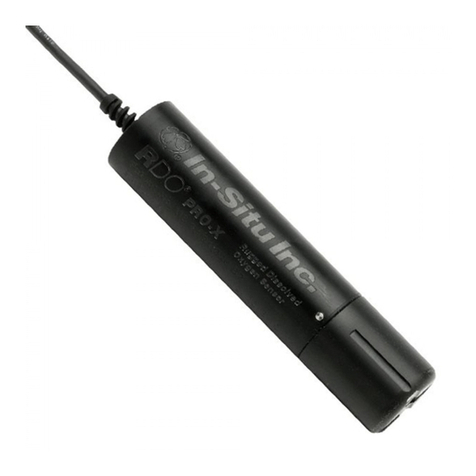
Optical RDO PRO-X Dissolved Oxygen Probe Specications���������������������������������������������������������������������� 5
Optical RDO PRO-X Dissolved Oxygen Probe...................................................................................................................... 5
Introduction���������������������������������������������������������������������������������������������������������������������������������������������������� 6
System Description ....................................................................................................................................................................... 6
Serial Numbers................................................................................................................................................................................ 7
Unpack the Probe .......................................................................................................................................................................... 7
Calibrate the RDO PRO-X Probe �������������������������������������������������������������������������������������������������������������������� 9
1-Point Calibration......................................................................................................................................................................... 9
2-Point Calibration.......................................................................................................................................................................10
Probe Deployment ��������������������������������������������������������������������������������������������������������������������������������������� 11
Care and Maintenance ��������������������������������������������������������������������������������������������������������������������������������� 12
Clean the Sensor Cap..................................................................................................................................................................12
Clean the Optical Window ........................................................................................................................................................12
Clean the Probe ............................................................................................................................................................................12
Sensor Cap Storage.....................................................................................................................................................................12
Replace the Sensor Cap .............................................................................................................................................................12
Maintain Desiccant......................................................................................................................................................................13
Controller Requirements and Connections������������������������������������������������������������������������������������������������ 14
Wire Diagram.................................................................................................................................................................................14
Power Connections .....................................................................................................................................................................15
Communications..........................................................................................................................................................................15
Enabling analog output.............................................................................................................................................................15
Analog (4-20 mA) wiring diagram..........................................................................................................................................15
SDI-12 wiring diagram ...............................................................................................................................................................16
Modbus (RS485) wiring diagram............................................................................................................................................17
Modbus (RS232 with converter) wiring diagram .............................................................................................................18
Converter ........................................................................................................................................................................................18
Conguring SDI-12 Settings������������������������������������������������������������������������������������������������������������������������ 19
About SDI-12 .................................................................................................................................................................................19
Congure SDI-12 Settings in VuSitu......................................................................................................................................19
Modbus PLC Interface ���������������������������������������������������������������������������������������������������������������������������������� 19
Overview.........................................................................................................................................................................................19
Setting Up Instrument ...............................................................................................................................................................20
Programming the PLC ................................................................................................................................................................20
1-970-498-1500 3www.in-situ.com


