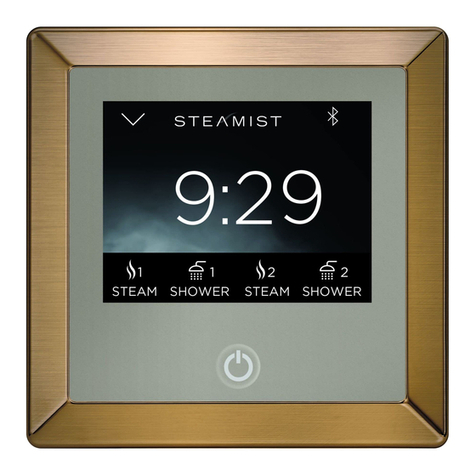
Steamist TSC User manual

SELECT
1½“ Hole
located four feet
from the floor
Double-Sided
Adhesive Pad
IMPORTANT: Run the
Control Cable through
a ¾” conduit.
Coupler
To Steam Generator
^
^
MENU
^
^
^
^
12
®
110°F
STEAM
112°
03 : 38 : 17 112
°
2
1
3
4
5
6
7
®
C US
®
LISTED 995C
WARNING: Elderly persons, pregnant women, or those suffering from heart disease, high blood pressure, diabetes, or
who are otherwise not in good health, do not use this device unless directed to do so by a physician. Also, do not use
steambath while under the influence of alcohol.
!
IMPORTANT: The TSC Control will only function with one of the following Steamist Generator models: TSG-7, TSG-10 or TSG-15
steam generators.
Installation Instructions
Steambath Control
Installation Instructions
Model: TSC
Control Features
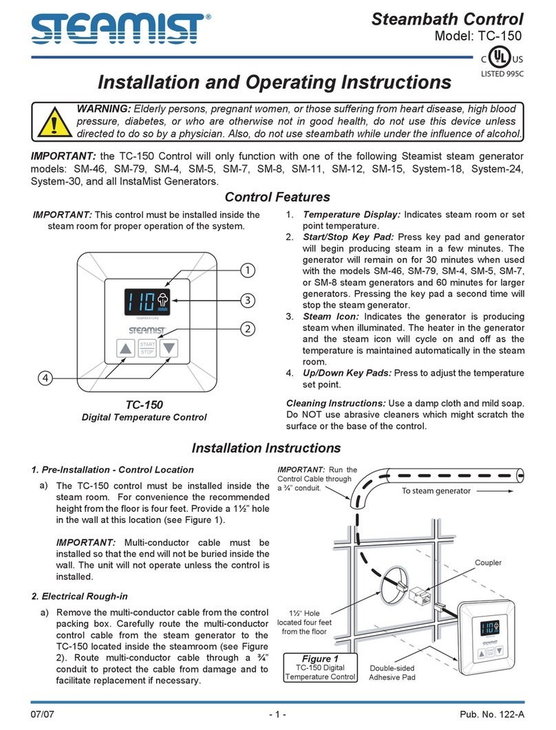
1.Set Point: Indicates steamroom setpoint temperature.
2. Temperature Display: Indicates ambient room temperature.
3. ON/OFF Keypad: Press keypad to start the system as a
guest user. Press the Keypad any time the system is on to
turn it off.
4. Navigation Keys: UP/Down Arrows, Menu, and Select.
5. User 1 / User 2: Press to select Pre-Set user settings.
6. Clock: Displays current time.
7. Duration: Remaining time of the system cycle.
IMPORTANT: Control must be installed inside the steam- room
for proper operation of the system.
Cleaning Instructions: Use a damp cloth and mild soap. Do
NOT use abrasive cleaners which might scratch the surface or
the base of the control.
1.Pre-Installation - Control Location
The TSC Control must be installed inside the steam- room.
For convenience the recommended height from the floor is
four feet. Provide a 1½" hole in the wall at this location (see
Figure 1).
IMPORTANT: Multi-conductor cable must be installed so
that the end will not be buried inside the wall. The unit will
not operate unless the control is installed.
2. Electrical Rough-in
Remove the multi-conductor cable from the control packing
box. Carefully route the multi-conductor control cable from
the steam generator to the TSC located inside the steam-
room (see Figure 1). Route multi-conductor cable through a
¾" conduit to protect the cable from damage and to facilitate
replacement if necessary.
Total Sense Digital Control
Figure 1
02/09 Pub. No. 202-A
- 1 -
®

ENOCILIS
R
AE
LC
.
Z
O.
LF
2
/
1
t
eN 025
13
.
oNm
e
t
I
.
A
.S
.U
NI
E
D
A
M
Knockouts for
Strain Relief
Clamps
¾" Conduit
To Control
Coupler
Control Cable
to Generator
Adhesive Liner
®
Relay
Board Power
Board
Fuses Ground
Connection
Modular Jacks:
All four modular jacks are
identical and will work in
any combination.
Connect into any jack.
3. Control and Cable Installation
a) Locate the previously installed cable and black plastic
strain relief clamp which is in the control packing box.
Locate the knockout on the steam generator for the
control cable (see Figure 1).
b) Place strain relief around cable about seven inches from
the end and insert into the hole. Remove the protective
covering labeled “Remove Before Installation” from the
modular jack found on the PC board.
c) Remove the protective cap from the multi-conductor
cable plug. Connect the cable to the modular jack.
d) Close and secure generator cover.
e) Locate Telco Jack at female coupler, on back of the
TSC control. Remove the protective covering labeled
“Remove Before Installation”. Remove protective cap
from cable and plug into jack. Check that the orientation
of the plug properly aligns with the jack. A snap will
indicate the plug is installed correctly (see Figure 2).
WARNING: Test the control for operation before
continuing on to the next step.
f) Peel adhesive liner from back of the control. Apply the
control to the wall. Press firmly and hold for a few
seconds.
g) After the control is in place, apply silicone (supplied)
around the control to form a watertight seal.
IMPORTANT: The adhesive on the back of the TSC control
will NOT seal this control. It is the responsibility of the
installer to seal this control to the wall with the supplied
silicone. Water damage to the control is not covered by
the warranty.
Figure 4
Figure 3
Figure 2 - Cable Installation on Steam Generator
02/09 Pub. No. 202-A
- 2 -
Installation Instructions
Installation Instructions Model: TSC
®®

1/2"
Aromatherapy
Reservoir
Back Plate
O-Ring MUST
seal to inside of
the Back Plate
Cover Plate
Center Hub
3/4" NPT (Brass Pipe)
Must use sealant tape
Apply silicone around
the back edge of Back
Plate to seal and
prevent movement
3/8" Hex Key
Hole
Apply silicone around
the steam pipe to form a
watertight seal
Apply a small
amount of
silicone to
prevent
movement
IMPORTANT:
Install top first
MUST be vertical
After inserting the top,
snap in the bottom
®
Installation Instructions for Steamhead &
Center Hub
1. Make sure the 3/4" nipple protrudes beyond the tile
approximately 1/2" (see Figure 5).
2. Wrap the nipple with pipe sealant tape.
3. Put a bead of silicone around the outer edge of the Back
Plate (see Figure 5) and center the Back Plate over the pipe
in an upright position. While holding it in place screw the
Center Hub onto the nipple, using a ⅜" Hex Key to tighten.
4. The Center Hub MUST be aligned with the four walls in the
vertical and horizontal position (see Figure 6). Make sure the
steamhead O-ring is fully seated into the Back Plate. If the
nipple is sticking out too far the O-ring will not make a proper
seal and the nipple must be adjusted.
5. Apply a small amount of silicone at the back center point of
the Cover Plate. This will aid in preventing movement of this
plate (see Figure 6).
6. Place the Cover Plate over the Center Hub. This is accom-
plished by first hooking the top and then snapping the bottom
into place.
7. Adjust the Back Plate and Cover Plate to line up squarely,
and clean excess silicone with rubbing alcohol.
Figure 6 - Center Hub Installation
Figure 5 - Steamhead Installation
02/09 Pub. No. 202-A
- 3 -
Installation Instructions
Installation Instructions Model: TSC
®®

®
Steamhead Installation
Steamhead should be mounted
18" above the finished floor or 6"
above the rim of the tub as far
from the bather as possible
Required Inside Installation
TSC Control. Locate away
from the direct line of shower
spray and do NOT locate
above steamhead.
^
^
MENU
^
^
^
^
12
®
All Instructions must be given to the homeowner for future use.
Figure 7 - Installation Suggestions
Installation Instructions Model: TSC
The Total Sense Control (TSC) has a built in temperature
sensor and therefore requires the TSC control to be installed
inside the steam room.
Max Temperature setting: 120°F
Max Time setting: 60 Minutes
02/09 Pub. No. 202-A
- 4 -
Installation Instructions
East Coast Office: 25 E. Union Ave., East Rutherford, NJ 07073 • Tel: 800-577-6478 • Fax: 201-933-0746
West Coast Office: 315 W. Pondera St., Suite F, Lancaster, CA 93534 • Tel: 800-355-6478 • Fax: 661-940-1617
®

^
^
MENU
^
^
^
^
12
®
110°F
STEAM
112°
03 : 38 : 17 112
°
SELECT
iPod
^
^
^
^
Cycle Timer
Audio Input Selected
Dual function keys are used
to start user 1 or 2 programs
and to skip forward or
backward on the iPod playlist.
Menu navigation keys
Room Temperature
User 2 indicator shown, one
icon indicates user 1 and
no icon indicates the guest.
Clock
Temperature Setting
Temperature Setting
Power ON/OFF button and
Guest Setting
User 1 Icon
70°F
STEAM
112°
03 : 38 : 17 112
°
STEAM
112°
03 : 38 : 17 112
°
:59
Remaining
Cycle Time
Figure 3Figure 2
C US
®
Operation Model: TSC
Programming and Operating Instructions
Operation Model: TSC
Figure 1: Total Sense Digital Control
02/08 Pub. No. 207-A
- 1 -
The Total Sense Control (TSC) has a built in temperature sensor and therefore MUST be installed inside the steam room.
Programming the User Settings
To program User 1, press the user 1 select button. The display
will show the User one icon. It will also show the steam bath
temperature settings, as shown in Figure 2. In the steam
mode the set temperature is easily adjusted with the Up and
Down arrows (Figure 2).
WARNING: Elderly persons, pregnant women, or those suffering from heart disease, high blood pressure, diabetes, or
who are otherwise not in good health, do not use this device unless directed to do so by a physician. Also, do not use
steambath while under the influence of alcohol.
!
Press the Select button and the remaining cycle time is shown.
The time may be adjusted up or down from 0-60 minutes.
Adjusting the time in this window only alters the current cycle
(Figure 3).
®

®
Total Sense Control
Cycle Timer
System Settings
Control Settings
Figure 4
Cycle Timer (mins)
60
Figure 5
70°F
AudioSense
VOLUME
03 : 38 : 17 112
°
MUSIC B
Figure 6
AudioSense
VOLUME
BASS
TREBLE
BALANCE
INPUT
MUSIC B
Figure 7
70°F
ChromoSense
WHITE
03 : 38 : 17 112
°
Figure 8
70°F
AromaSense
PUMP 2
03 : 38 : 17 112
°
Off
Figure 9
02/08 Pub. No. 207-A
- 2 -
Operation Model: TSC
To adjust the default cycle time, press and hold the MENU
button until the setup window is displayed. This displays the
system setting discussed later in this document and also is
where the default timer is changed (Figure 4).
With the CYCLE TIMER highlighted, Press select. Use the
arrow Up or Down buttons to adjust the default time cycle for
that current user (Figure 5).
Press the MENU button to back out of the current display
which will bring you back to the TOTAL SENSE CONTROL
screen, Press the MENU button again to return to the USER 1
STEAM screen. Press the MENU button a third time and if the
AudioSense option is installed the display will show the
AudioSense Mode. In this mode pressing the Up or Down
arrows changes the volume. The bottom of the display shows
the selected audio input (Figure 6).
Pressing the SELECT button while in AudioSense mode, gives
you more options to adjust you music settings. Press the select
button again until the setting you want to adjust is highlighted.
Then use the Up or Down arrow buttons to adjust that setting.
High light INPUT to select between iPod, Music A and Music
B. Music A is the 3.5 mm phone jack input on the left side of
the TSC control module. Music B is the RCA jacks on the side
of the TSC control module (Figure 7).
Programming and Operating Instructions
Press the MENU button to return to the previous AudioSense
Mode.
Press the MENU again to switch to ChromaSense mode.
While in the ChromaSense mode, use the select button to
toggle between the different ChromaSense mood lights. Use
the arrow keys to adjust the light intensity (Figure 8).
Press the MENU button to toggle the AromaSense mode. The
selected pump either 1 or 2 is shown. To change the selected
pump, press the select button. Pressing the select button
toggles between pump 1 and 2. To adjust the intensity of the
oil press the Up or Down button. The lowest ON setting is
slightly less than one drop per minute and the highest setting is
about 5 drops per minute. To turn the selected pump off press
the down button until the word OFF is displayed (Figure 9).
Press the MENU button again to return to the Steam mode.
This completes all the user settings for User 1. To set up
USER 2 press the power OFF button to turn the power off.
Then press USER 2 and repeat the above steps for the custom
settings for User 2.
NOTE: 2 user icons will be shown in the display. The guest
setting which is selected by pressing the power button when
the control is off and indicated by no user icons in the display
programs the same as User 1 and 2. The guest setting works
as a third user setting.

®
Off
InstaMist
Figure 11
AudioSense Input
MUSIC A
MUSIC B
iPod
Figure 12
F
Temperature Units
Figure 13
NO
Restore Defaults
Figure 14
Figure 15
Gen 1 YES
Gen 3 NO
AudioSense
ChromoSense
AromaSense
Outside Control
Wireless Remote
NO
NO
v10
v10
v10
NO
NO
Gen 2
Gen 4
Total Sense Control
Cycle Timer
System Settings
Control Settings
Figure 10
02/08 Pub. No. 207-A
- 3 -
Programming the System Settings Model: TSC
Programming and Operating Instructions
Programming the System Settings
Power on TSC control by pressing either USER 1, USER 2 or
the power button. Press and hold the MENU button to enter
the setup window. You will see the Cycle timer that was
programmed earlier and the "System Settings." Highlight
"System Settings" using the Up or Down arrows and press
select (Figure 10).
The first system setting is INSTAMIST. This selects the instant
on feature which keep the water hot and ready for your next
steam bath. This feature uses an average of 60 watts of
electricity to keep the water hot. If the steam bath is not used
for long periods of time you may prefer to turn this setting off.
When this feature is turned on you may hear a slight rumbling
sound occasionally as the heater is periodically cycled on for a
few seconds.
With Instamist highlighted in the display press select. The
INSTAMIST is turned on and off with the Up or Down arrows
(Figure 11).
Press MENU to return to the previous display. The next system
setting is AudioSense Input. Highlight AudioSense and press
select. This setting allows you to further adjust the volume
based on the input level of the audio source connected to the
TSC Control Module. Use the SELECT button to toggle
between the three input choices. These settings should start at
the lowest settings. Use the arrow Up or Down buttons to
increase or decrease the input volume boost. The iPod setting
should be set at the lowest setting. Depending on the audio
source connected to the Music A and B you may need to
increase the input boost to get a more acceptable volume
level. This is a global setting for all users. After making
changes to these settings you will need to re adjust the volume
for each user (Figure 12).
Press MENU to return to the previous display. The next system
setting is Temperature Fahrenheit or Celsius setting. Select
this setting and change between the F and C with the Up or
Down arrows (Figure 13).
Press MENU to return to the previous display. The next system
setting is Restore Defaults setting. This setting is intended to

return the control to the factory setting. Select this setting and

change between yes and no with the arrow Up or Down
arrows. If yes is selected the defaults will be restored when the
Menu button is pressed after yes is selected (Figure 14).
Press MENU to return to the previous display. The next system
setting is Connected Devices. Selecting this displays a list of
the connected devices. This is used for troubleshooting
purposes to determine if all the devices are properly connected
and communicating with the control (Figure 15).

®
Total Sense Control
Cycle Timer
System Settings
Control Settings
Figure 16
Total Sense Control
Set Time
Clock Display
Display Contrast
Display Backlight
Keypad Backlight
Figure 17
03:14
Figure 18
ON
Clock Display
Figure 19
LCD CONTRAST
Figure 20
LCD BACKLIGHT
Figure 21
KEY LIGHTING
Figure 22
Programming the Control Settings Model: TSC
02/08 Pub. No. 207-A
- 4 -
Programming and Operating Instructions
Press the MENU button twice to enter the setup window.
Highlight Control Settings and press the select button (Figure
16).
Set Time is already highlighted press the select button to
change the time (Figure 17).
Change the hour with the Up or Down arrow. Press SELECT to
toggle between hours and minutes. Use the arrow buttons to
change the minutes. The clock will keep time even with a brief
power interruption of less than a day (Figure 18).
Press MENU to return to the previous display. The next control
setting is the clock display. This setting turns the clock function
on or off. With the clock display highlighted press select and
use the arrow buttons Up or Down to turn the clock function on
or off (Figure 19).
Press MENU to return to the previous display. The next control
setting is the display contrast. If necessary this setting adjusts
the contrast for optimum viewing. With the LCD Contrast
highlighted press select and use the arrow buttons Up or Down
to adjust the contrast (Figure 20).
Press MENU to return to the previous display. The next control
setting is the LCD Display Backlight adjustment. If desired to
adjust the LCD backlight, highlight this selection and press
select. Use the arrow buttons Up or Down to adjust the
Backlight (Figure 21).
Press MENU to return to the previous display. The next control
setting is the Keypad Backlight adjustment. If desired to adjust
the Keypad backlight, highlight this selection and press select.
Use the arrow buttons Up or Down to adjust the backlight
(Figure 22).
Press the power button to exit and turn off.
East Coast Office: 25 E. Union Ave., East Rutherford, NJ 07073 • Tel: 800-577-6478 • Fax: 201-933-0746
West Coast Office: 315 W. Pondera St., Suite F, Lancaster, CA 93534 • Tel: 800-355-6478 • Fax: 661-940-1617
®

4"
5⅝"
SELECT
^
^
MENU
^
^
^
^
12
®
110°F
STEAM
112°
03 : 38 : 17 112
°
ENOCILIS
R
A
ELC
.
Z
O.
LF
2
/
1
te
N0
2
51
3
.
oNm
e
t
I
.
A
.
S
.U
NI
E
D
A
M
25-Ft. Multi-Conductor Cable
Strain Relief Clamp
Silicone Sealant
360-Degree Diffusing
Steamhead
6-Pin Coupler
®
®
®
Specications
02/09 Pub. No. 214-A
Steambath Control Model: TSC
- 1 -
TSC
Product Information – TSC
5-years parts warranty
Programmable Time and Temperature.
Operates AromaSense, AudioSense and ChromaSense options.
Digital display of ambient and set temperature.
Icons for system status - heating and set temp.
Dimensions: 4" x 5⅝"
Package Includes: Control, 25-Ft. Multi-Conductor Cable,
6-Pin Coupler, Steamhead (Delivers 360-Degree Steam Disper-
sion), Strain Relief Clamp, Silicone Sealant, Installation and
Operating Instructions.
Required Electrical Service:
Low-voltage connection from
TSG generator via multi-conductor cable (supplied).
Notes
Package Contents
Installation Notes:
Surface Mount - 1½" hole required.
Mounts inside the steam room.
Steamist recommends that the multi-conductor cable be run
through ¾" conduit to protect cable from damage and to facilitate
easy replacement.
Mount control near seating area and not above steamhead.
Rough-in Notes:
Control should be mounted 48" above the floor.
Steamhead to be mounted 18" above the finished floor or
6" above the rim of the tub and as far from the seating area
as possible.
Product No. - Finishes:
TSC-PC - Polished Chrome
TSC-PN - Polished Nickel
TSC-BN - Brushed Nickel
TSC-AB - Antique Brass
TSC-PB - Polished Brass
TSC-PG - Polished 24K Gold
TSC-ORB - Oil-Rubbed Bronze
®

®
Special Light Cable
StandardSpeakerWire
Control Cable
120V
120V
Category 5 Cable
Tube
StandardSpeakerWire
Tube
Control Cable
®
START
1START
2
STOP
TSR
Remote
Control
Wireless
Receiver
..
.
.
.
..
.
.
.
.
...
..
.
.
.
..
.
.
.
.
...
..
.
.
.
..
.
.
.
.
...
..
.
.
.
..
.
.
.
.
...
..
.
.
.
..
.
.
.
.
...
..
.
.
.
..
.
.
.
.
...
..
.
.
.
..
.
.
.
.
...
..
.
.
.
..
.
.
.
.
...
..
.
.
.
..
.
.
.
.
...
..
.
.
.
..
.
.
.
.
...
..
.
.
.
..
.
.
.
.
...
..
.
.
.
..
.
.
.
.
...
..
.
.
.
.
.
.
.
.
..
.
.
.
..
.
.
.
.
...
..
.
.
.
..
.
.
.
.
...
..
.
.
.
.
.
.
.
.
.
.
.
.
.
.
.
.
.
..
.
.
.
..
.
.
.
.
...
..
.
.
.
..
.
.
.
.
...
..
.
.
.
..
.
.
.
.
...
..
.
.
.
..
.
.
.
.
...
..
.
.
.
..
.
.
.
.
...
..
.
.
.
..
.
.
.
.
...
..
.
.
.
..
.
.
.
.
...
..
.
.
.
..
.
.
.
.
...
..
.
.
.
..
.
.
.
.
...
..
.
.
.
..
.
.
.
.
...
..
.
.
.
..
.
.
.
.
...
..
.
.
.
..
.
.
.
.
...
..
.
.
.
.
.
.
.
.
..
.
.
.
..
.
.
.
.
...
..
.
.
.
..
.
.
.
.
...
..
.
.
.
.
.
.
.
.
.
.
.
.
.
.
.
.
.
..
.
.
.
..
.
.
.
.
...
..
.
.
.
..
.
.
.
.
...
..
.
.
.
..
.
.
...
..
.
.
.
.
.
.
.
.
.
..
.
.
..
.
.
.
.
..
..
.
.
.
..
.
.
.
.
...
..
.
.
..
.
.
.
.
...
iPod
Cradle
TSC
Control
®
CONTROL CABLECONTROL CABLE
TSC Digital
Control
Module
Aroma
Box
^
^
MENU
^
^
^
^
12
®
110°F
STEAM
112°
03: 38 :17 112
°
Aroma
Injection Tee
TSS-CL
Invisible
Speakers
TSS-CL
Classic
Speaker
Specications
02/09 Pub. No. 214-A
Wiring Layout
- 2 -
East Coast Office: 25 E. Union Ave., East Rutherford, NJ 07073 • Tel: 800-577-6478 • Fax: 201-933-0746
West Coast Office: 315 W. Pondera St., Suite F, Lancaster, CA 93534 • Tel: 800-355-6478 • Fax: 661-940-1617
®
This manual suits for next models
1
Table of contents
Other Steamist Control Panel manuals
Popular Control Panel manuals by other brands

Vitrum
Vitrum Scene Installation and operation

Grasslin
Grasslin talento 800 Series operating instructions

Honeywell
Honeywell GF505 manual

Matrix Switch Corporation
Matrix Switch Corporation MSC-CP64X1E product manual

DoorHan
DoorHan PCB-SW Programming instructions

Eaton
Eaton COOPER POWER SERIES installation instructions