Steelcase Ology User manual

Ology™Single Sided Bench
888.STEELCASE
X
No children
Sin hijos
Pas d'enfants
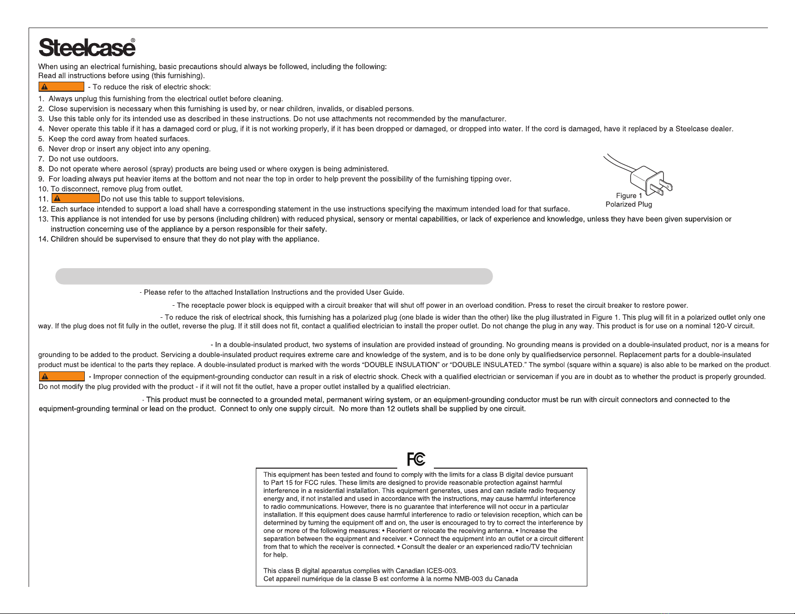
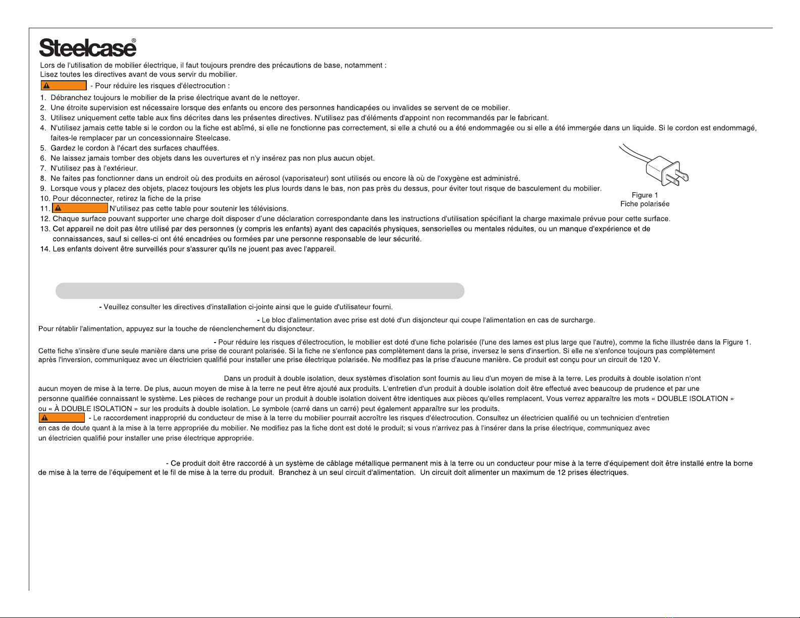
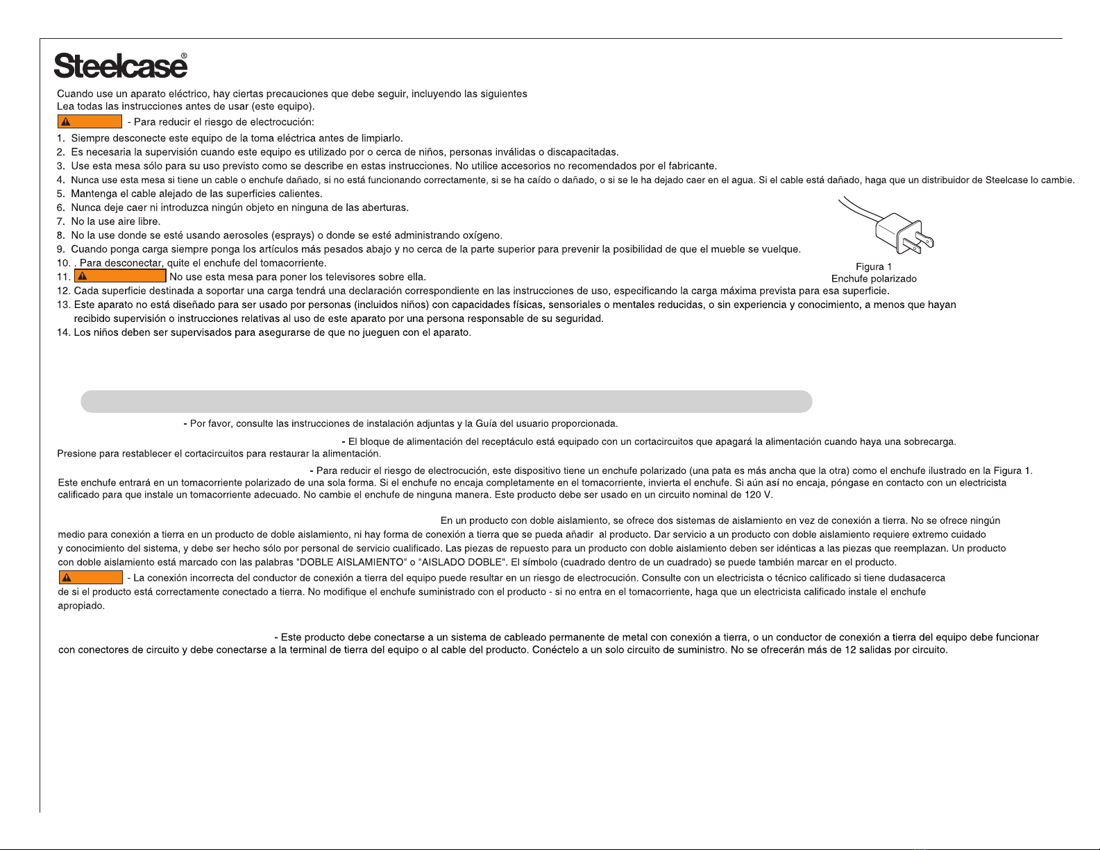
Read Directions and Manual first
Lea primero las instrucciones y el manual
Lisez d'abord les directives et le guide
Leia as Instruções e o Manual primeiro
Crush Hazard - Keep Clear
Peligro de aplastamiento – Manténgase alejado
Risque d'écrasement - Demeurer à l'écart
Perigo de esmagamento - Afaste-se
?
Max.
Min.
X
X
RISK OF DEATH OR SERIOUS INJURY.
DO NOT ALLOW USE BY CHILDREN
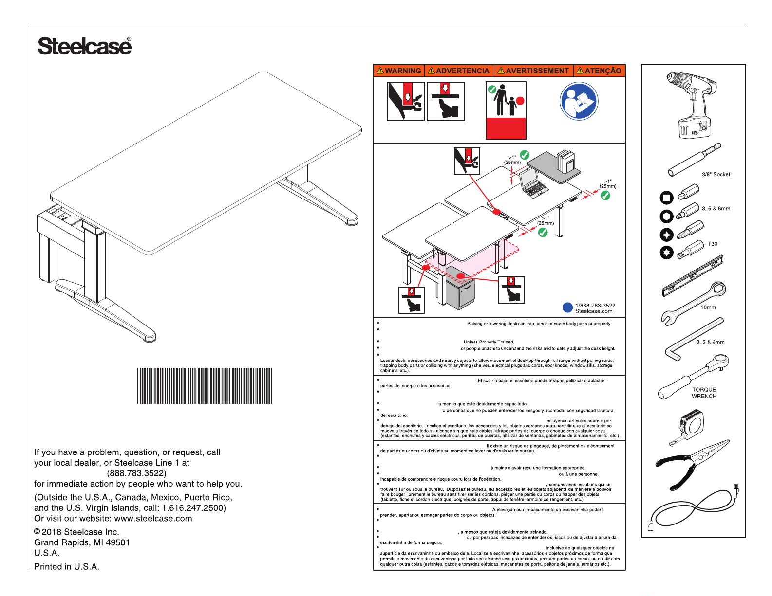
Maintain > 1" (25mm) gap above objects on desk at max. height and between the desk and adjacent objects.
RIESGO DE MUERTE O DE LESIÓN GRAVE.
RISQUE DE DÉCÈS OU DE GRAVE BLESSURE.
ÉVITEZ DE CONFIER LE RÉGLAGE DE LA HAUTEUR DU BUREAU Á UN ENFANT
Conserver un dégagement d'au moins 25 mm (1 po) tout autour du bureau,
NO DEBEN USARLO NIÑOS
Mantenga > 1 pulgada (25 mm) de distancia alrededor de todo el escritorio,
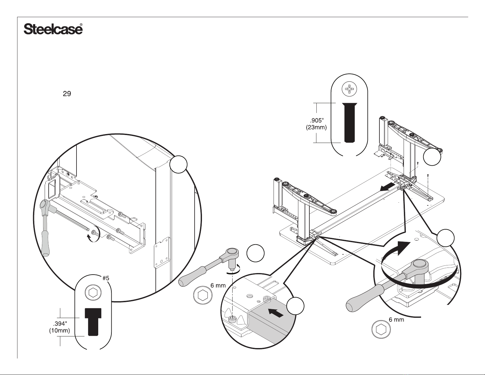
CRUSH HAZARD – DO NOT PLACE FEET OR OTHER BODY PARTS UNDER MODESTY SCREENS,
ON CROSSBAR OR ON OBJECTS PLACED UNDER TABLE TOP.
DO NOT OPERATE THIS EQUIPMENT
PELIGRO DE APLASTAMIENTO - NO COLOQUE LOS PIES U OTRAS PARTES DEL CUERPO DEBAJO DE LAS
PANTALLAS MODESTY, EN LA BARRA TRANSVERSAL O EN OBJETOS COLOCADOS BAJO LA TABLA SUPERIOR.
RISQUE D'ÉCRASEMENT - NE PLACEZ PAS LES PIEDS OU AUTRES PIÈCES DU CORPS SOUS LES ÉCRANS DE
MODESSE, SUR LA BARRE TRANSVERSALE OU SUR LES OBJETS PLACÉS SOUS LE DESSUS DE TABLE.
NO OPERE ESTE EQUIPO
NE PAS FAIRE FONCTIONNER CET ÉQUIPEMENT
RISCO DE MORTE OU DE FERIMENTOS GRAVES.
PERIGO DE CRUSH - NÃO COLOQUE OS PÉS OU OUTRAS PARTES DO CORPO DEBAIXO DO PAINEL
CENTRAL, NO CROSSBAR OU OBJETOS COLOCADOS DEBAIXO DA MESA.
NÃO UTILIZE ESTE EQUIPAMENTO
NÃO PERMITA O USO POR CRIANÇAS
Mantenha um espaço livre de 1 polegada (25mm) em volta da escrivaninha,
Proibidas crianças
X
X
1266052001
Page 1 of 33
1266052001 Rev D
#2

The power socket/outlet shall be installed near the equipment and shall be easily accessible.
IMPORTANT SAFETY INSTRUCTIONS
SAVE THESE INSTRUCTIONS
DANGER
OPERATING INSTRUCTIONS
USER-MAINTENANCE INSTRUCTIONS
POLARIZED PLUG INSTRUCTIONS
No adapter should be used with this product.
SERVICING OF DOUBLE-INSULATED PRODUCTS
DANGER
WARNING
GROUNDING INSTRUCTIONS
Page 2 of 33
1266052001 Rev D

La prise de courant doit être située près du mobilier et doit être facilement accessible.
CONSERVEZ CES DIRECTIVES
MODE D'EMPLOI
DIRECTIVES D'ENTRETIEN À L'INTENTION DE L'UTILISATEUR
DIRECTIVES RELATIVES À LA FICHE POLARISÉE
Aucun adaptateur ne doit être utilisé avec ce produit.
ENTRETIEN DES PRODUITS À DOUBLE ISOLATION -
DANGER
IMPORTANTES DIRECTIVES DE SÉCURITÉ
DANGER
ATTENTION
DIRECTIVES DE MISE À LA TERRE
Page 3 of 33
1266052001 Rev D

El enchufe de alimentación/tomacorriente debe estar instalado cerca del equipo y debe ser fácilmente accesible.
INSTRUCCIONES IMPORTANTES DE SEGURIDAD
GUARDE ESTAS INSTRUCCIONES
INSTRUCCIONES DE USO
INSTRUCCIONES DE MANTENIMIENTO PARA EL USUARIO
PELIGRO
ADVERTENCIA
INSTRUCCIONES PARA EL ENCHUFE POLARIZADO
No se debe utilizar un adaptador con este producto.
PRESTACIÓN DE SERVICIOS A LOS PRODUCTOS CON DOBLE AISLAMIENTO -
PELIGRO
INSTRUCCIONES DE CONEXIÓN A TIERRA
Page 4 of 33
1266052001 Rev D

A tomada/saída de alimentação deverá ser instalada perto do equipamento e estar facilmente acessível.
IMPORTANTES INSTRUÇÕES DE SEGURANÇA
GUARDE ESTAS INSTRUÇÕES
INSTRUÇÕES DE OPERAÇÃO
INSTRUÇÕES DE MANUTENÇÃO PARA O USUÁRIO
PERIGO
INSTRUÇÕES SOBRE O PLUGUE POLARIZADO
Nenhum adaptador deve ser usado com este produto.
PERIGO
ATENÇÃO
MANUTENÇÃO DE PRODUTOS COM ISOLAMENTO DUPLO
INSTRUÇÕES DE ATERRAMENTO
Page 5 of 33
1266052001 Rev D

®
23” 1
2x
2x
2x
2x
2x
2x
2x
2x
2x
2x
2x
29”
1
35”
Page 6 of 33
1266052001 Rev D

®
FRONT
.905"
(23mm)
3x
3
10x
Optional Grommets
NOTE: Thicker edgeband is front of worksurface.
NOTE: Attach one leg only
Page 7 of 33
1266052001 Rev D

2X
7b
6
5b
2X
7a
NOTE: Steps 4a, 4b, and 6 not required
for fixed height legs.
4b
4a
4a
Longer cable - 2 M
Shorter cable - 1 M
FRONT
5a
Loosen
Bolts
Tube Orientation:
Hole on tube can be placed on the
Left or Right Hand side depending
on User Preference.
Hole on tube can face front or back.
Place towards back if there is no
Cable Tray or Basket. Page 8 of 33
1266052001 Rev D

8X
25 Nm
(221 in-lbs)
3x
10a
11
2X
10b
8x
8
9 8X
NOTE: If stabilizer is required and installing at an
end of run or on a standalone bench, follow steps
on page for assembly prior to step 9.
Page 9 of 33
1266052001 Rev D

BACK
FRONT
Placement of Control Box
If you have a Cable Basket or Power Access Door in the Back, place Control Box in the Front of the Frame Tube.
Otherwise, place the Control Box behind the Frame Tube for best knee clearance.
Place Control Box on the same side as the desired User Switch location (Left or Right).
______________________
Page 10 of 33
1266052001 Rev D

12
OR
NOTE: Not required for fixed height legs.
To Strain Relief
Power Cord
Page 11 of 33
1266052001 Rev D

2X
14
13
2X
15
NOTE: Gasket for Simple Touch Only.
See Arrow for correct orientation.
14
NOTE: Steps 13 - 15 not required for fixed height legs.
Page 12 of 33
1266052001 Rev D

Max.
Min.
2X
X
X
15
20
19
1
NOTE: Steps 16 - 20 not required for fixed height legs.
22.6"
or
27.3"
For Active Touch Only:
Extended Leg: 22.6" to 48.7"
Basic Leg: 27.3" to 46.4"
Tap the Switch. Each time it is
pressed, it will toggle between
22.6" and 27.3", the 2 different
starting heights.
22.6" = Extended Legs
27.3" = Basic Legs
Once the desired height is
achieved, let go of the switch for
more than 3 seconds and the
setting will stay permanently.
Press down to initialize the
desk, holding for 3 seconds.
After initialization, the legs will
now adjust vertically.
Page 13 of 33
1266052001 Rev D
Extended Leg
NOTE: Extend to full height
to check cable clearances.
Basic Leg

20
4X
21
NOTE: Step 20 not required for fixed
height legs.
Page 14 of 33
1266052001 Rev D

Power Block Assembly:
Hardwire (continue to Page 16)
1a
Only required if
'High Capacity'
has been ordered.
Standard Capacity = 1 block
High Capacity = 2 blocks
NOTE: For proper fit of
receptacle, remove all
ears on receptacle
BEND DOWN
NOTE: This equipment has been tested and found to comply with the
limits for a Class A digital device, pursuant to part 15 of the FCC rules.
These limits are designed to provide reasonable protection against
harmful interface when the equipment is operated in a commercial
environment. This equipment generates, uses and can radiate radio
frequency energy and, if not installed and used in accordance with the
instruction manual, may cause harmful interference to radio
communications. Operation of this equipment in a residential area
is likely to cause harmful interference in which case the user will be
required to correct the interference at his own expense.
USB RECEPTACLE
OR
OR
Power Block Assembly:
Modular Power
Page 15 of 33
1266052001 Rev D

2
NOTE: Steps 3a through 3c are also
required on all Power-In feeds.
3b
1
3a
3c
Modular Version
NOTE: If receptacles are not
required inside a power block,
make sure to apply a receptacle
cover to ALL open ports.
Two power blocks shown. Single power
block installs in left or right position.
Only on 34" size will it be centered.
Page 16 of 33
1266052001 Rev D

Hardwire Option
1
NOTE: Steps 3a through 3c are also
required on all Power-In feeds.
3b
3a
3c
WARNING: All electrical installations should be done by a qualified
person in accordance with codes and regulations applicable at the
installation site. Circuits should be checked for proper voltage. Note
Chicago Only: Must be hard wired under authority of a permit by a
contractor licensed in the City of Chicago.
2
Two hardwire boxes shown. Single power
block installs in left or right position.
Only on 34" size will it be centered.
Page 17 of 33
1266052001 Rev D

1
2
3
5X
4X
Bench-to-Bench Attachment
4X
4
If stabilizer post is and installing with a
bench-to-bench connector, complete step then
follow steps on page for assembly prior to step .
Used on
connector.
Used for trim
pieces.
2
Page 18 of 33
1266052001 Rev D

Bench-to-Bench Power
3b 3c
3a
1
2
Page 19 of 33
1266052001 Rev D

New York Power In-Feed
4X
2
1
3a
3b
3c
Page 20 of 33
1266052001 Rev D
Other manuals for Ology
13
Table of contents
Popular Tools Storage manuals by other brands

TRINITY Pro
TRINITY Pro 72" 12-DRAWER STAINLESS STEEL ROLLING... owner's manual

Henny Penny
Henny Penny HC-941 user manual

Edsal
Edsal MBI MRWB52COS manual

DIVERSIFIED WOODCRAFTS
DIVERSIFIED WOODCRAFTS WW31-0V SERIES Assembly instructions

Triton
Triton LocBoard LB18-T Installation & assembly instructions

Seville Classics
Seville Classics UltraHD 20283B Assembly instructions