Reference to other information in
the document�
2� General safety notification
• This product must only be installed by a
qualified electrician in accordance with
national wiring regulations as defined in
VDE 08 29 (DIN EN 5000 90).
• Installed improperly, low-voltage products
can cause extremely serious personal injury
or damage to property.
• This product must never be connected to
the mains supply voltage (240 V AC) as it
is intended for connection to an extra-low
voltage power supply.
3� iHF 3D KNX
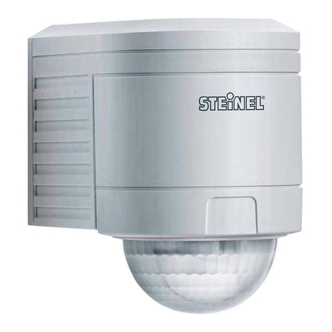
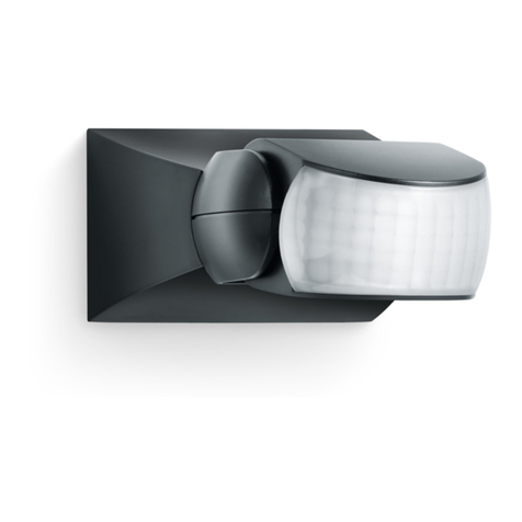
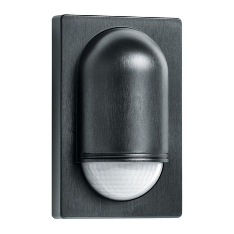
Suitable for wall mounting, the iHF 3D KNX is
an active motion detector for outdoors. The
iHF 3D KNX emits high-frequency electromag-
netic waves (5.8 GHz) and receives their echo.
Any movement by persons in the detection
zone is noticed by the sensor as a change in
echo and triggers a switching signal. Analysing
the signal, the iHF 3D KNX distinguishes
between moving persons and moving objects,
such as bushes or small animals. The 3D
antenna system permits precision adjustment
in three directions. This rules out any inad-
vertent triggering by small animals as well as
!
interference from extreme temperatures. All
function settings can also be made via the
RC9 remote control
(➔"7� Accessories")
Note:
The high-frequency output of the iHF sensor
is approx. 1 mW – that's 1000 times less than
the transmission power of a mobile phone or
the output of a microwave oven.
Package contents (Fig� 3�1)
Product dimensions (Fig� 3�2)
Reach / mounting height (Fig� 3�3)
Product components (Fig� 3�4)
A Wall mount
B Programming button
C KNX bus plug connection
D Designer trim
E 3D reach setting
F Sensor unit
4� Mounting / installation
• Check all components for damage.
• Do not use the product if it is damaged.
Mounting procedure
• Select an appropriate mounting location,
taking the reach and motion detection into
consideration (Fig� 3�3)
• Switch OFF power supply (Fig� 4�1)
• Mark drill holes (Fig� 4�2)
• Drill holes and fit wall plugs
– Concealed wiring (Fig� 4�3)
– With spacers for surface-mounted cables
(Fig� 4�4)
Wiring diagram (Fig� 4�5)
When selecting the wiring leads (Fig� 4�6), it is
important to meet the installation regulations
specified in VDE 08 29 (DIN EN 500090).
• Make plug connection (C) (Fig� 4�7)
• Screw sensor unit (F) into place (Fig� 4�8)
• Switch ON power supply (Fig� 4�9)
• Make settings
➔"6� Operation"
5� Commissioning
Note: to calibrate the presence detector,
please go to www.knx.steinel.de
1. Issue physical address and generate
calibration program in the ETS.
2. Load the physical address and calibration
program into the presence detector. When
you are prompted, press programming
button B.
3. The white LED goes out once programming
has been successfully completed.
6� Operation
Note:
After connecting, the white status LED flashes
for 10 seconds. The sensor is then ready for
operation.
Factory settings
Time setting: install
Reach setting: 3 x 7 m
Light-level setting: 200 lux
Functions
Reach setting (Fig� 6�2 / E 1-3)
The reach can be infinitely adjusted from
1-7 m in three directions (independently of
each other) via 3 control dials. The maximum
detection reach is selected using the control
dials.
Detection diagram (Fig� 6�3)
Note: if the distance to a wall or similar struc-
ture is less than 7 m in any of these directions,
the reach in that direction must still be set to
the maximum reach or detection errors may
occur. The reach settings should only be used
to mask out areas in which you do not want
movement to result in light being switched ON.
7� Accessories
Remote control RC9 (Fig� 7�1)
(EAN 4007841007638)
Any number of iHF 3D KNX sensors can be
controlled via the RC9 remote control. The
status LED on the sensor flashes (once) to
indicate each valid press of the button. The
status LED flashes (twice) to indicate each
invalid press of the button.
Functions:
1
Light-level setting
The chosen response threshold can
be set from approx. 2-2000 lux.
2
Daylight operation
3
Night-time operation
4
Light-level setting via the memory
button / teach mode. This button
must be pressed at the level of light
at which you want the sensor to
respond to movement from now on.
The current value is stored.
5
Time setting
The period of time you want the
light to stay ON for after the last
detected movement can be set to
10 s, 1 min, 5 min or 15 min by
pressing these buttons.
6
Setting the light to stay ON for a
time of your own choice. Each
press of the button increments
the current time setting by 1 min
(up to 30 min).
7
Pressing this button switches the
light ON for 4 hours (status LED
on). The light then returns to sensor
mode automatically. Pressing the
button for a second time (before
the 4 h period expires) returns the
light to sensor mode.
GB
