Stentofon LBB 7026/65 Installation instructions manual

MOUNTING GUIDE
BI-WAY STARTER KIT
LBB 7026/65
2009.09.01
MI 23614 v.1.2

GENERAL DESCRIPTION
The Bi-Way system is designed for hands-free, voice-controlled duplex conversation
between counter personnel (operator) and their customers on the other side of a glass partition.
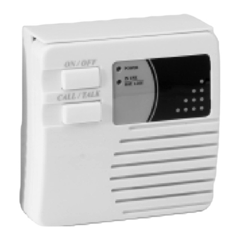
The operator’s unit is easy to fit on the operator’s counter or wall. The operating modes are marked with logical symbols
and indicated by information lights.
The loudspeakers and microphone on the public side can be mounted in alternative ways and are easy to fit on any
surface such as glass, wood, metal or concrete.
In addition to the basic Bi-Way kit there are several optional elements, e.g. operator’s gooseneck microphone, handset or
headset with microphone for noisy areas, flush-mount loudspeakers for public side and hearing aid radiator.
Area of Application
Bi-Way is ideal for areas where security from violence and vandalism is essential or where noise or health problems●
are of importance such as:
Cash counters in banks and post offices–
Embassies–
Petrol stations–
Gates and doors to restricted areas–
Ticket counters in railway stations and airports–
Treatment labs and isolation wards in hospitals–
Bi-Way Units
Bi-Way starter kit, LBB 7026/65
Bi-Way operator’s unit LBB 7026/60●
Bi-Way external microphone LBB 7026/73●
Bi-Way loudspeaker kit LBB 7026/80●
Power supply LBB 7102/60●
Accessories
Bi-Way gooseneck microphone LBB 7026/71●
Bi-Way external microphone LBB 7026/73●
Bi-Way flush-mount loudspeaker kit LBB 7026/81●
Bi-Way hearing aid kit LBB 7026/82●
Headset with microphone LBB 7026/83●
Flush-mount back box - 60 mm LBB 7073/61●
Flush-mount frame LBB 7073/70●
Handset with cradle kit LBB 7073/82●
Cradle bracket LBB 7073/84●
MI 23614 v.1.2 - 2 - GB
2009-09-01

INSTALLATION
General Mounting
The different parts of the Bi-Way system are mounted on either side of a glass partition as shown in the figure below.
Public Side
There are several ways to mount the loud-
speakers and the public microphone.
Some general examples are shown below.
The mounting of accessories such as
gooseneck microphone, hearing aid
radiator and flush-mount loudspeakers are
described in separate instructions packed
together with the items.
These instructions are also found on the
web site
www.stentofon.com
GB - 3 - MI 23614 v.1.2
2009-09-01

www.vingtor.com
STENTOFON and VINGTOR products are developed and marketed by Zenitel Norway AS. The company’s Quality Assurance System is certified to meet the requirements in NS-EN ISO 9001:2002.
Zenitel Norway AS reserves the right to modify designs and alter specifications without prior notice, in pursuance of a policy of continuous improvement. © 2009 Zenitel Norway AS.
support@vingtor.com
DOC NO
A100K10XXX v.1.0
LBB 7026/80 - Bi-way Loudspeaker kit
The kit contains:
2 x loudspeakers in plastic cabinets for surface mounting–
10 m 2-wire cable–
Decide the loudspeaker placement and fastening method.●
The loudspeakers should be mounted on each side of the customer’s area●
with the distance between loudspeakers = 60-100 cm.
They may be mounted in one of the following ways:●
on the glass with self-adhesive tape–
on the frame or wall with screws–
on the counter with self-adhesive tape or screws–
Open the loudspeaker boxes by pressing a thin screwdriver into the
slot at the base or through the holes in the rear.
Drill a hole in the cabinet for the cable according to loudspeaker placement
and fastening method.
Drill a corresponding hole in the wall for the loudspeaker cable.
You may choose to drill one hole for each item or select a convenient place
for a common hole including the microphone cable.
Route the loudspeaker cable through the wall from the operator’s side and
through the hole in the loudspeaker cabinet.
Tie a knot on the cable 15 cm from the end as a strain relief and pull the
cable back.
Mount the cabinet on the surface as decided and ensure there is sufficient
space behind the loudspeakers to open the cabinets for subsequent service
of the elements.
Self-adhesive tape:
Clean the glass screen and loudspeaker cabinet with alco-pad before position-
ing the cabinets.
Screws:
3-4 holes must be drilled in the rear or base of the cabinet. Do not use the holes
for opening the cabinet!
Solder the cable to the loudspeaker terminals making sure the marked
wire is connected to the + terminal.
Mount the loudspeaker front, be sure the logo is horizontal at the bottom
left.
MI 23614 v.1.2 - 4 - GB
2009-09-01

www.vingtor.com
STENTOFON and VINGTOR products are developed and marketed by Zenitel Norway AS. The company’s Quality Assurance System is certified to meet the requirements in NS-EN ISO 9001:2002.
Zenitel Norway AS reserves the right to modify designs and alter specifications without prior notice, in pursuance of a policy of continuous improvement. © 2009 Zenitel Norway AS.
support@vingtor.com
DOC NO
GB - 5 - MI 23614 v.1.2
2009-09-01
LBB 7026/73 - Bi-way Public Microphone
The type number contains a hyper cardioid microphone with base for screw●
mounting and a Velcro pad for mounting on an even surface.
The microphone is delivered with 5m shielded cable prepared for screw●
terminals.
Decide the placement of the microphone.
The microphone front should always point in the direction of the customer, e.g.
an area in the middle of the glass about 1.6 m above the floor.
Never point the microphone towards a loudspeaker.
The distance to the nearest loudspeaker should be at least 150 mm.
The microphone can be mounted in two ways:
1. Use two screws (A) to fix the mounting base to a wooden or concrete
surface. Note the direction of the base!
By using one screw through the middle hole (B) the microphone–
Snap the microphone onto the base.–
2. Attach one part of the Velcro pad to either the base plate or directly on the
microphone base.
- Clean the glass with an alco-pad, and press the other part of the Velcro pad
to the glass.
- Press the microphone on place.
Drill a hole in the wall in a convenient place and route the cable through
the hole into the operator’s room.
Connect the microphone cable to the operator’s unit as explained in “Connections” page .
Options
On the customer’s side optional equipment may be mounted to ease or improve the communication. The mounting of
these items are described separately.
Hearing aid kit, LBB 7026/82
Loop antenna to serve customers wearing a hearing aid.
Description is found in manual 3924 985 24212.
Flush-mount loudspeaker(s), LBB 7026/81
Used for alternative loudspeaker mounting, description is found in manual 3924 985 24412.
Gooseneck microphone, LBB 7026/71
Can be used to reduce extreme background noise. Connect to the public mic. input.
Movement detector
The operator’s unit is prepared for use with a movement detector to automatically switch from standby mode to duplex
mode when a customer is present at the counter.
This item is not included in the Bi-Way range and must be acquired locally.
direction can be adjusted after mounting.

www.vingtor.com
STENTOFON and VINGTOR products are developed and marketed by Zenitel Norway AS. The company’s Quality Assurance System is certified to meet the requirements in NS-EN ISO 9001:2002.
Zenitel Norway AS reserves the right to modify designs and alter specifications without prior notice, in pursuance of a policy of continuous improvement. © 2009 Zenitel Norway AS.
support@vingtor.com
DOC NO
MI 23614 v.1.2 - 6 - GB
2009-09-01
Mounting the movement detector
The physical mounting depends on local circumstances and detector type.
Typical mounting would be above the counter glass or in the ceiling. Be sure the
detector does not react on incidental bystanders or persons at a neighboring
counter.
Connections
Route the switch/power cable(s) from the detector through one of the sta-
tion breakouts and secure by a strain relief.
Connect the n.o. switch cable to P12-1(+) and P12-4 and the detector
power cable to P1-5(+) and P1-6(–)
Operation
Place the operator’s unit in standby mode (push the green button). The●
movement detector will switch to operating mode when activated.
The standby mode must be reestablished by pushing the green button once●
when the customer leaves.
The sound damping on the operator’s side is -6 dB in standby mode. If●
more damping is required the value of R39 (3K3) could be lowered.
Operator’s Side
Basically the operator’s unit and the
power supply are the only units on the
operator’s side.
The operator’s unit can be●
placed freestanding on the desk,
fastened to the wall by screws or
flush-mounted in the desk or wall
Alternative microphones and●
handset may be connected to the
station.

www.vingtor.com
STENTOFON and VINGTOR products are developed and marketed by Zenitel Norway AS. The company’s Quality Assurance System is certified to meet the requirements in NS-EN ISO 9001:2002.
Zenitel Norway AS reserves the right to modify designs and alter specifications without prior notice, in pursuance of a policy of continuous improvement. © 2009 Zenitel Norway AS.
support@vingtor.com
DOC NO
GB - 7 - MI 23614 v.1.2
2009-09-01
LBB 7026/60 - Operator’s Unit
Decide where to place the unit for ease of operation. The distance to the built-in microphone should normally be less than
50 cm2to ensure safe voice switching. Consider the necessity for optional microphone types to reduce the influence of
background noise. Consult your dealer for advice. The optional microphones may be mounted at a later stage.
Desk Mounting
The unit has rubber feet for stable placement on any horizontal surface. Allow sufficient length of cable to the unit from the
public loudspeaker, microphone and power for alternative positions on the desk.
Wall Mounting
There are two keyhole openings in the station’s rear cover.
Use screws through these holes to mount the station to the wall.
Flush Mounting
Mount the flush mount frame LBB 7073/70 to the station front and make a cut-out in the desk or wall as described in the
instruction.
The station may be mounted with or without the 60 mm flush-mount back box LBB 7073/61.
Connections
Open the station by inserting a thin object, e.g. paper
clip, through the small holes at the microphone end.
Separate the front and rear covers.
All connections are made to terminals on the board in the
front cover.
Remove the right breakout in the rear cover.
Route the loudspeaker, microphone and power cables
through the breakouts and leave 15 cm of cable inside
the station.
Secure the cables with the cable clamp.
Connect the cables to the screw terminal according to
drawing (also found under the rear cover).
Please note the polarization!
The screw terminal is plugable and may be removed●
from the board at any time.

www.vingtor.com
STENTOFON and VINGTOR products are developed and marketed by Zenitel Norway AS. The company’s Quality Assurance System is certified to meet the requirements in NS-EN ISO 9001:2002.
Zenitel Norway AS reserves the right to modify designs and alter specifications without prior notice, in pursuance of a policy of continuous improvement. © 2009 Zenitel Norway AS.
support@vingtor.com
DOC NO
MI 23614 v.1.2 - 8 - GB
2009-09-01
Power supply, LBB 7102/60
The power supply is connected to a 230 V a.c. mains power outlet. This supply cannot be set for other mains voltages. A
12 V d.c. /500 ma supply must then be obtained locally.
The 12 V d.c. is connected to a screw terminal inside the station.
Up to 5 operator’s units can be powered from one supply.
Gooseneck microphone, LBB 7026/71
Mount the optional gooseneck microphone to improve the signal/
noise level on the public side.
Break out the tinted field between the buttons and the loud
speaker.
Route the microphone cable through the opening, the spacer,
lock washer and nut. Tighten the nut on the microphone
threaded stud.
Insert the microphone plug in connector P9.
Close the solder-split N3 to activate the gooseneck microphone
function.
By pushing the yellow button you can toggle between built-in•
and gooseneck mic. The LED is lit when gooseneck is selected.
The gooseneck mic. can also be mounted on a separate stand.•
The cable is then routed through the left breakout in the
station’s rear cover.
Further instructions are given in the manual MI 23813.
Handset with cradle kit, LBB 7073/82
The standard intercom handset with cradle kit can be connected to
obtain low-speaking open duplex in heavy noise environments or for
confidential conversation on the operator’s side.
Mount the cradle to the wall by two screws or to the station by
using a cradle bracket LBB 7073/84, see instruction.
Remove the left breakout in the station rear cover.

www.vingtor.com
STENTOFON and VINGTOR products are developed and marketed by Zenitel Norway AS. The company’s Quality Assurance System is certified to meet the requirements in NS-EN ISO 9001:2002.
Zenitel Norway AS reserves the right to modify designs and alter specifications without prior notice, in pursuance of a policy of continuous improvement. © 2009 Zenitel Norway AS.
support@vingtor.com
DOC NO
GB - 9 - MI 23614 v.1.2
2009-09-01
Route the cradle cable through the opening and secure with a cable clamp.
Connect the 4-pin plug to P9 and the 2-pin plug to P10.
Open the solder-split A to activate the reed switch.
Close the solder-split N1 to set the handset microphone level.
The station will switch to low-speaking mode on lifting handset.•
Headset with microphone, LBB 7026/83
A headset with microphone is available as an alternative to the normal handset..
An optional switch will toggle between high- and low speaking mode.●
Further instructions are found in manual MI 24413.
External microphone, LBB 7026/73
A freestanding microphone with flexible mounting may substitute the built-in microphone where the distance to the opera-
tor’s unit is too far.
This microphone is plugged into connector P4.●
Further instructions are found in manual MI 23914.
ADJUSTMENTS
The volume in the operator’s unit and on the public side can
be adjusted individually without opening the station.
The volume controls are accessed by means of a small
screwdriver through an opening under the station. The
potentiometers are clearly marked.
Adjust the sound volume to a suitable level on both
sides of the partition.
Simplex Mode Setting
By default the station is set for duplex operation with the possibility to force the speech direction towards the public side
amplified by +6 dB. Solder split N4 is closed on delivery.
It is possible to set the system to push-to-talk / release-to-listen simplex mode with normal amplification both ways.•
Open solder split N4 situated in the middle of the station board.

www.vingtor.com
STENTOFON and VINGTOR products are developed and marketed by Zenitel Norway AS. The company’s Quality Assurance System is certified to meet the requirements in NS-EN ISO 9001:2002.
Zenitel Norway AS reserves the right to modify designs and alter specifications without prior notice, in pursuance of a policy of continuous improvement. © 2009 Zenitel Norway AS.
support@vingtor.com
DOC NO
MI 23614 v.1.2 - 10 - GB
2009-09-01
TECHNICAL SPECIFICATIONS
LBB 7026/65 - Bi-Way Starter Kit
LBB 7026/60 - BI-WAY OPERATOR’S UNIT
Dimensions (WxHxD) 93 x 65 x 224 mm
Weight (net) 350 g
Environmental condition cat. T1, CE requirements
Supply voltage 12.0 V d.c. ±0.5 V
Current consumption typ. 100 ma
min. 42 ma, max. 180 ma
Output power, public side max. 500 mW
Output power, operator’s unit max. 350 mW
LBB 7026/73 - BI-WAY EXTERNAL MICROPHONE
Type AKG C 400 BL Hypercardioid, electret
Frequency range 150 - 12000 Hz ± 6dB
Dimensions (L x H x D) 43 x 24 x 12 mm
Sensitivity at 1000 Hz 13.5 mV/Pa, -37 dBV
Shielded cable 5 m
LBB 7026/80 - BI-WAY LOUDSPEAKER KIT
2 cabinets silver brown ABS plastic
Dimensions (WxHxD), each 105 x 106 x 62 mm
Weight, each 180 g
Loudspeaker element Philips AD 3071/Y50
Power capacity 2 W max.
Impedance 50 ohms
Cable length, total 10 m
LBB 7102/60 - POWER SUPPLY
Dimensions (WxHxD) 100 x 51 x 63 mm
Weight 450 g
Input voltage 230 V a.c. +6/-10%, 50-60 Hz
Mains connection EURO PLUG
Output voltage standard 12 V d.c. ±0.5 V
adjustable range 5-15 V d.c.
Output current at 12 V max. 500 mA (8 W)
Protection Double insulated housing
Thermal fuse in trafo, Thermal protected regulator
OPTIONAL EQUIPMENT
Gooseneck microphone 220 mm, Electret, 7.2 mV, 1 Kohm
Handset LBB 7073/82
Headset with microphone LBB 7072/26
Headset/mic. kit LBB 7072/25
External microphone Electret, 0.5-1.0 mV
Flush mount loudspeaker > 2 W, 16 - 50 ohms
Hearing aid kit max. 15 m2 area coverage
Movement detector I.R., 12 V d.c., N.O. switch contact
Further data are found in the instructions packed with the products.

www.vingtor.com
STENTOFON and VINGTOR products are developed and marketed by Zenitel Norway AS. The company’s Quality Assurance System is certified to meet the requirements in NS-EN ISO 9001:2002.
Zenitel Norway AS reserves the right to modify designs and alter specifications without prior notice, in pursuance of a policy of continuous improvement. © 2009 Zenitel Norway AS.
support@vingtor.com
DOC NO
GB - 11 - MI 23614 v.1.2
2009-09-01
USER GUIDE
Normal Mode
Default setting
ON / OFF
Push the blue button once to turn ON the station LED is lit●
Push once to turn OFF an active station LED is off●
MICROPHONE SELECTOR
The button is active only when a gooseneck microphone is mounted.
Push the yellow button to toggle between built-in and gooseneck micro-●
phones. LED is lit when the gooseneck microphone is selected
STANDBY
The sound is reduced by -6 dB
Push the green button once to force speech direction towards the•
operator, LED is lit
Push again to return to duplex operation mode, LED is off•
SIMPLEX (in STANDBY mode)
’Standby’ is selected, LED is lit
Push and hold the pink button to make an announcement to the public•
side. The sound is increased by +6dB, LED is off
Release the button to return to standby mode•
PUSH-TO-TALK (in DUPLEX mode)
The sound is increased by +6 dB
Push and hold the pink button to force the speech direction towards the●
public side, LED is off
Release the button to return to duplex mode, LED is off●

www.vingtor.com
STENTOFON and VINGTOR products are developed and marketed by Zenitel Norway AS. The company’s Quality Assurance System is certified to meet the requirements in NS-EN ISO 9001:2002.
Zenitel Norway AS reserves the right to modify designs and alter specifications without prior notice, in pursuance of a policy of continuous improvement. © 2009 Zenitel Norway AS.
support@vingtor.com
DOC NO
ON / OFF
Push the blue button once to turn ON the station LED is lit●
Push once to turn OFF an active station LED is off●
MICROPHONE SELECTOR
The button is active only when a gooseneck microphone is mounted
Push the yellow button to toggle between built-in and gooseneck microphones.●
LED is lit when the gooseneck microphone is selected
STANDBY
The sound is reduced by -6 dB
Push the green button once to force speech direction towards the operator,•
LED is lit
Push again to return to duplex operation mode, LED is off•
SIMPLEX (in STANDBY mode)
’Standby’ is selected, LED is lit
Push and hold the pink button to make an announcement to the public•
side. The sound is increased by +6dB, LED is off
Release the button to return to standby mode•
USER GUIDE - SIMPLEX MODE
SIMPLEX (from DUPLEX mode)
’Standby’ LED is off
Push and hold the pink button to force speech direction towards public side,•
normal sound level, LED is lit
Release to listen, LED is still lit•
Push the green standby button twice to return to duplex mode, LED is off•
DOC NO
MI 23614 v.1.2
www.stentofon.com Zenitel Norway AS - P.O. Box 4498 Nydalen - NO-0403 Oslo - Norway
STENTOFON and VINGTOR products are developed and marketed by Zenitel Norway AS. The company’s Quality Assurance System is certified to meet the requirements in NS-EN ISO 9001:2002. Zenitel
Norway AS reserves the right to modify designs and alter specifications without prior notice, in pursuance of a policy of continuous improvement. © 2009 Zenitel Norway AS.
Other manuals for LBB 7026/65
1
Table of contents
Other Stentofon Intercom System manuals

Stentofon
Stentofon 100 7007 000 User manual
Stentofon
Stentofon 1401110100 Instruction sheet

Stentofon
Stentofon IP Substation User manual
Stentofon
Stentofon Pulse System User manual
Stentofon
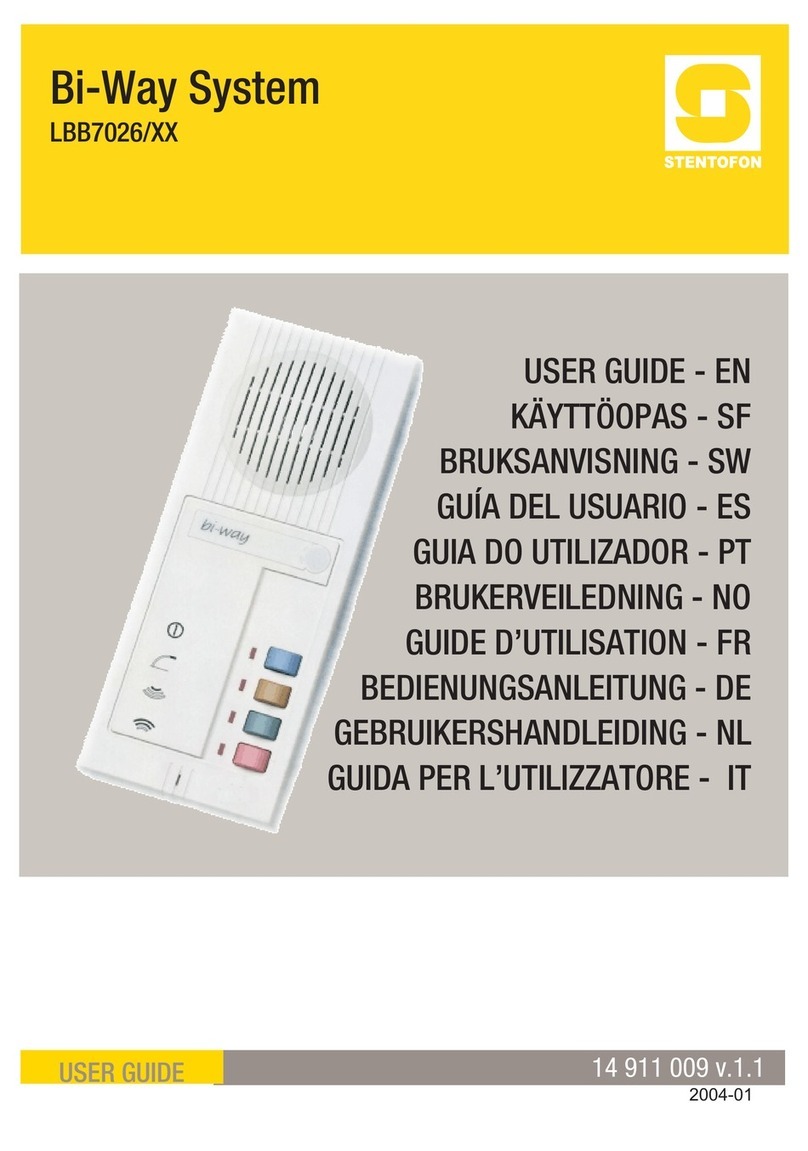
Stentofon LBB 7026/65 User manual
Stentofon
Stentofon ALPHACOM E A100K10602 User manual

Stentofon
Stentofon IP Master Series User manual
Stentofon
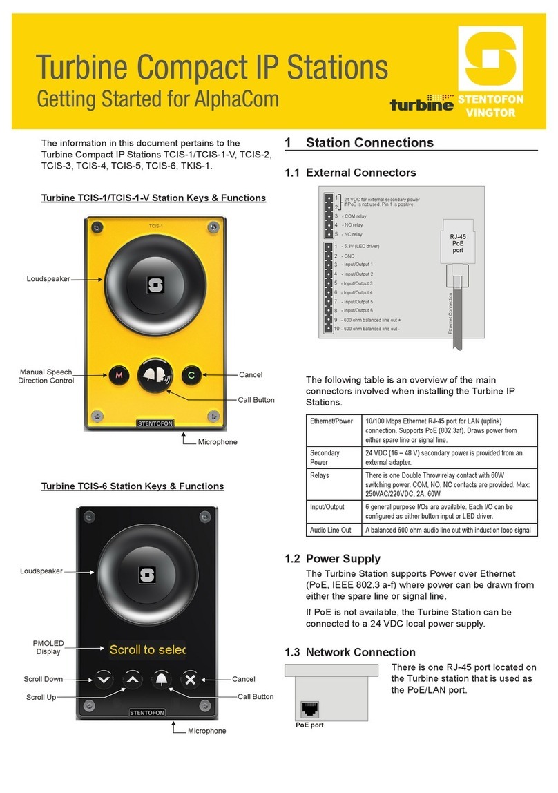
Stentofon Turbine Compact Series User manual

Stentofon
Stentofon Pulse System User manual

