manuals.online logo
Brands
  1. Home
  2. •
  3. Brands
  4. •
  5. STILLA
  6. •
  7. Garden House
  8. •
  9. STILLA S3031 User manual

STILLA S3031 User manual

STILLA
ASSEMBLY INSTRUCTIONS
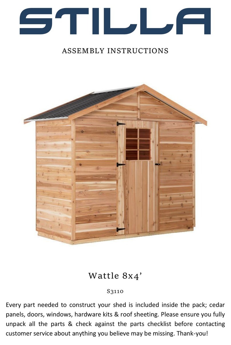
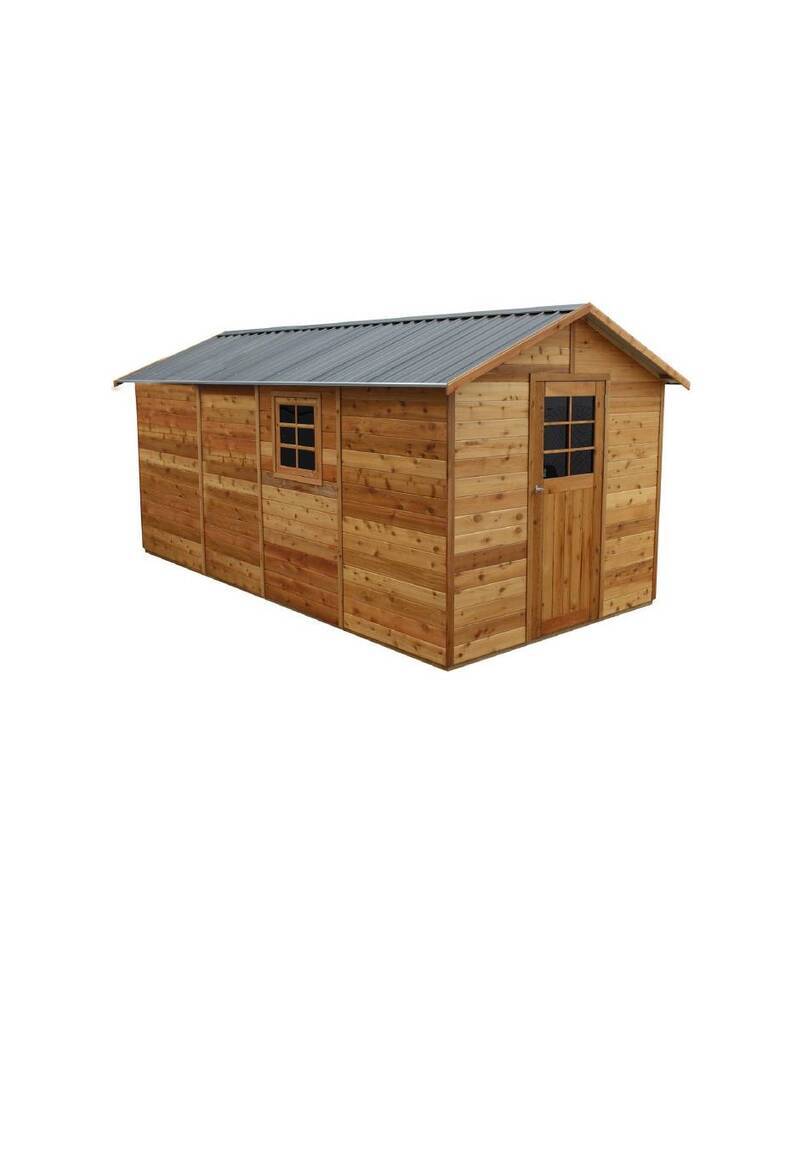
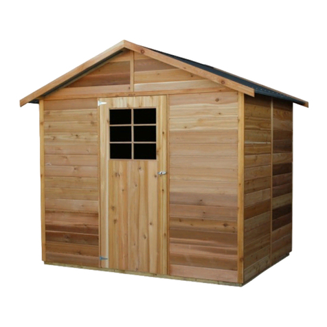
‘Glendale’8x8
S3031
Every part needed to construct your shed is included inside the pack; cedar
panels, doors, windows, hardware kits & roof sheeting. Please ensure you fully
unpack all the parts & check against the parts checklist before contacting
customer service about anything you believe may be missing. Thank-you!
1 | P a g e
Caution
Please be careful when handling all components, some parts have sharp metal edges.
Always wear work gloves, eye protection and long sleeves when assembling or maintaining
your shed.
Tools required for assembly
•Level
•Drill
•Hammer
•Ladder
•12mm Drill bit
•6mm Drill bit
•Phillips head drive
•Hex Head Drive (5/16’)
•Safety glasses
•Gloves
Before assembly
•Before proceeding with installation, we recommend viewing the Cedar Shed video at
www.stilla.com.au/installation/ or search Stilla Classic Cedar Sheds on Youtube. This doesn’t
show the installation in detail however it could give you some handy tips. Please note we
haven’t videoed the assembly of each shed however the video online is the Maple 12x6 and
will give you an overall idea on how the installation process is completed.
•Remove all parts from packages and place in a safe place close to assembly area.
•Review all instructions; continue to refer to instructions throughout assembly –step
by step.
Preparing your site
•If you are installing your shed on the Stilla rebated floor we recommend finding a
place in your yard that is very close to level. Pavers or a solid material that will not be
affected by weather can be used to perfectly level the shed by placing under the
floor frame where required, make sure all members are supported.
•If you are installing your shed on the Stilla heavy duty floor, this can be placed on
unlevelled surfaces and levelled up by using the 100x100 stumps provided.
2 | P a g e
GLENDALE 8x8 PARTS CHECKLIST
Part Code
Checked
Part Description
Qty
P
Cedar Clad Panel 1200x1895mm
6
FP
Cedar Clad Panel 780x1895mm(480x1895mm if Double Doors)
2
CD
Colonial Door 830x1875mm (714x1875mm if double doors)
1
G
8ft Gable (2 x LHS, 2 x RHS)
4
CP
Corner Post 1890x61x18mm
4
CS
Cover Strip 1890x40x7mm
3
F
8ft Fascia Pack (4)
1
R
Roof Rafter 1195x70x45mm
8
CT
Collar Tie
2
DH
Door Head 840x35x42mm (1440mm if double doors)
1
DS
Door Step 840x42x19mm (1440mm if double doors)
1
E
Roof End Piece 203x70x30mm
12
FGS
Front Gable Cover Strip –460mm
1
BGS
Back Gable Cover Strip –490mm
1
SCS
Stilla Cover Strip 2400x40x7mm (1@ 1800mm, 1@ 600mm)
1 & 1
RS
1450mm Roof Sheeting
8
RC
1520mm Ridge Cap
2
C
1360mm Channel
4
HK
8x8 Hardware Kit
1
IM
8x8 Instruction Manual
1
REP
Roof End Plate 1157x70x45mm
8
JP
Joining Plate 712x70x45mm
4
Floor Kit –Option
Floor Frame - 140x38mm
Part Code
Checked
Part Description
Qty
EP
End Plate 1242mm
8
DJ
Double Joist 1124mm
4
SJ
Single Joist 1124mm
12
FN
Floor Nog 376x42x35mm
6
L
Logs 750mm
9
FB
1798mm x 800mm
2
FB
598mm x 800mm
2
FB
1798mm x 711mm
1
FB
598mm x 711mm
1
3 | P a g e
Double Doors –Option –Changes to above kit
Part Code
Part Description
Qty
CD
Colonial Door 714x1875mm
2
FP
Cedar Clad Panel 480x1895mm
2
DH
Double Door Head 1440x42x35mm
1
DS
Double Door Stop 1440x42x18mm
1
DP
Door Leaver Packer 100x100x18mm
1
Annex Kit –Option (add screws)
2720mm x 1400mm
Part Code
Checked
Part Description
Qty
VBJ
Veranda Beam Joiner 700x70x45mm
1
VOBJ
Veranda Outer Beam Joiner 700x140x35mm
1
VB
Veranda Beam 1360x70x45mm
2
VOB
Veranda Outer Beam 1360x140x35mm
2
VR
Veranda Rafter 1320x70x45mm
4
VF
Veranda fascia 1350x75x20 block cedar
2
VRS
1450mm Veranda Roof Sheet
4
VP
Veranda Posts 2400x90x90mm
2
4 | P a g e
If no floor option was purchased, go to step 2.0 (Wall Assembly)
SKIP TO BACK FOR IMAGES TO HELP WITH FLOOR INSTALL
STEP 1.0
FLOOR KIT
1.0 –FLOOR KIT (1 of 4 floor frames)
PART CODE
QTY
DESCRIPTION
EP
2
End Plate 1242mm
SJ
3
Single Joist 1124mm
DJ
1
Double Joist 1124mm
100BS
18
100mm Batten Screw
1.0 –FLOOR FRAME (1 of 4 floor frames)
Fasten floor frame together as indicated in diagram below, using lines and predrilled holes.
Screw through EP into DJ using 3x 100BS.
Screw through EP into SJ using 2 x 100BS per join.
Ensure frame is square by measuring from corner to corner diagonally, frame will be square
when both diagonal measurements equal the same.
REPEAT THIS PROCESS FOR FASTENING 3 MORE FLOOR FRAMES.
ENSURE 42x35 side of the DJ sits at top.
5 | P a g e
STEP 1.1
FLOOR FRAME INSTALLATION
The 8x8 floor frame comes in four parts. Install first floor frame in desired position at
desired height and fasten to logs once level and square, then join and fasten next frame
until all four are joined and secured to logs.
1.1 –FLOOR FRAME INSTALLATION
PART CODE
QTY
DESCRIPTION
L
9
Logs 750x100x100mm
100BS
36
100mm batten screws
65BS
24
65mm Batten Screws
200PB
9
200mm M12 Post Bolt
W
18
M12 Washers
1.1 –FLOOR FRAME INSTALLATION
Repeat the steps below for each floor frame, joining the floor frames together as you go in
order displayed in diagram below.
1. Lay out frame in desired position and mark holes to dig, as indicated on diagram
below (use shovel or marking paint).
2. Dig and place logs in holes (using concrete if you wish).
3. Fasten floor frame to logs at desired height, using 4x 100BS per log, ensuring frame is
level*.
4. Butt next floor frame into last installed frame and join using 6x 65BS evenly spaced
along EP or SJ.
5. Repeat process until all frames are joined.
* Fasten frame to logs when roughly level and then critique by hammering in or adding dirt
(or concrete) to corners until perfectly level at every post.
Once all frames are joined, predrill holes (using a 13mm drill bit) and bolt each log to the
floor frame in spots indicated with 200PB, using washers on both sides.
6 | P a g e
STEP 1.2
FLOOR NOG INSTALLATION
1.2 –FLOOR NOG INSTALLATION
PART CODE
QTY
DESCRIPTION
FN
6
Floor Nog 376x42x35mm
65HHS
12
65mm Hex Head Screws
1.2 –FLOOR NOG INSTALLATION
Mark out measurements shown below (centre of nog). Fasten Floor Nogs (FN) in positions
shown in diagram below using 1x 65HHS per join.
7 | P a g e
STEP 1.3
FLOOR INSTALLATION
1.3 –FLOORING INSTALLATION
PART CODE
QTY
DESCRIPTION
FB
4
Floor Board 1798x800mm
FB
4
Floor Board 598x800mm
FB
1
Floor Board 1798x311mm
FB
1
Floor Board 598x311mm
50PS
116
50mm Philips Screw
1.3–FLOORING INSTALLATION
Fasten floor sheets to floor frame as shown in diagram below using 50PS.
Bring Floor sheets in 43mm on all 4 sides from the outside of the floor frame.
Note- The x marked on the floor sheets do not line up with out joists.
8 | P a g e
STEP 2.0
WALL ASSEMBLY
2.0 - ASSEMBLY PARTS –WALL ASSEMBLY
PART CODE
QTY
DESCRIPTION
FP
1
Front Wall panel
P
1
1200mm Wall panel
65HHS
3
65mm Hex head screw
-If optional window was purchased, it can take the place of any 1200mm (P) panel.
2.0 - ASSEMBLY –WALL ASSEMBLY
Screw through FP into P (top, centre & bottom) using 3 x 65HHS. (Holding studs flush on the
outside)
Note: Ensure tongue on VJ cladding is facing upwards.
P
Screw 3 x 65HHS (Top,
centre & bottom)
FP
Cedar Strip
When screwing the four corners together please make sure the studs are flush on the
outside (not the inside) as per image below.
9 | P a g e
STEP 2.1
WALL ASSEMBLY
2.1 - ASSEMBLY PARTS –WALL ASSEMBLY
PART CODE
QTY
DESCRIPTION
P
1
1200mm Wall panel
65HHS
3
65mm Hex head screw
2.1 - ASSEMBLY –WALL ASSEMBLY
Screw through P into P (Top, centre & bottom) using 3 x 65HHS, holding studs flush on the
inside.
P
Screw 3 x 65HHS (Top,
centre & bottom)
FRONT OF SHED
P
10 | P a g e
STEP 2.2
WALL ASSEMBLY
2.2 - ASSEMBLY PARTS –WALL ASSEMBLY
PART CODE
QTY
DESCRIPTION
P
1
1200mm Wall panel
65HHS
3
65mm Hex head screw
2.2 - ASSEMBLY –WALL ASSEMBLY
Screw through P into P (Top, centre & bottom) using 3 x 65HHS, holding studs flush on the
outside.
P
Screw 3 x 65HHS (Top,
centre & bottom)
FRONT OF SHED
P
11 | P a g e
STEP 2.3
WALL ASSEMBLY
2.3 - ASSEMBLY PARTS –WALL ASSEMBLY
PART CODE
QTY
DESCRIPTION
P
1
1200mm Wall panel
65HHS
3
65mm Hex head screw
2.3 - ASSEMBLY –WALL ASSEMBLY
Screw through P into P (Top, centre & bottom) using 3 x 65HHS, holding studs flush on the
inside.
P
Screw 3 x 65HHS (Top,
centre & bottom)
P
FRONT OF SHED
12 | P a g e
STEP 2.4
WALL ASSEMBLY
2.4 - ASSEMBLY PARTS –WALL ASSEMBLY
PART CODE
QTY
DESCRIPTION
P
1
1200mm Wall panel
65HHS
3
65mm Hex head screw
2.4 - ASSEMBLY –WALL ASSEMBLY
Screw through P into P (top, centre & bottom) using 3 x 65HHS holding studs flush on the
outside.
Screw 3 x 65HHS (Top,
centre & bottom)
P
P
13 | P a g e
STEP 2.5
WALL ASSEMBLY
2.5 - ASSEMBLY PARTS –WALL ASSEMBLY
PART CODE
QTY
DESCRIPTION
P
1
1200mm Wall panel
65HHS
3
65mm Hex head screw
2.5 - ASSEMBLY –WALL ASSEMBLY
Screw through P into P (top, centre & bottom) using 3 x 65HHS holding studs flush on the
inside.
Screw 3 x 65HHS (Top,
centre & bottom)
FRONT OF SHED
P
P
14 | P a g e
STEP 2.6
WALL ASSEMBLY
2.6 - ASSEMBLY PARTS –WALL ASSEMBLY
PART CODE
QTY
DESCRIPTION
FP
1
Front Wall panel
65HHS
3
65mm Hex head screw
2.6 - ASSEMBLY –WALL ASSEMBLY
Screw through FP into P (top, centre & bottom) using 3 x 65HHS holding studs flush on the
outside.
Screw 3 x 65HHS (Top,
centre & bottom)
Cedar Strip
FP
P
15 | P a g e
STEP 2.7
DOOR STEP INSTALL
2.7 - ASSEMBLY PARTS –DOOR STEP INSTALL
PART CODE
QTY
DESCRIPTION
DS
1
840x42x19mm Door Step (Replace with 1440 DS if DD)
DS
1
1440x42x19mm Door Step (ONLY IF DOUBLE DOOR OPTION PURCHASED)
40N
4
40mm Nail
2.7- ASSEMBLY –DOOR STEP INSTALL
Nail Door Step in position using 4x 40N* as seen below. Ensure wall panels are tight against DS.
* This is if floor option was chosen. If you are installing on concrete slab, use small dyno bolts to
fasten (not provided).
16 | P a g e
STEP 2.8
BACK END GABLE ASSEMBLY
2.8 - ASSEMBLY PARTS –BACK END GABLE ASSEMBLY
PART CODE
QTY
DESCRIPTION
G
2
8ft Gable (left and right)
BGS
1
490mm Back Gable Cover Strip
65HHS
2
65mm Hex head screw
40N
5
40mm Nail
2.8 - ASSEMBLY –BACK END GABLE ASSEMBLY
Lay left and right gables (G) on a flat surface with the frame facing upwards, as seen below.
Hold flush at the bottom and screw together in position shown below using 2x 65HHS.
Turn fastened gable over with the cedar now facing upwards. Position BGS over join in gable,
holding bottom flush with bottom of cedar cladding and nail using 5x 40N.
Lay Gables on flat surface
Hold flush at the bottom and
fasten together with 2x 65HHS
Nail BGS on cedar side,
flush with bottom, to
cover join
17 | P a g e
STEP 2.9
BACK END GABLE INSTALL
2.9 - ASSEMBLY PARTS –BACK END GABLE INSTALL
PART CODE
QTY
DESCRIPTION
1
Assembled back end 8ft Gable
65HHS
6
65mm Hex head screw
2.9 - ASSEMBLY –BACK END GABLE INSTALL
Carefully place assembled gable on back wall, ensuring groove on gable slots into the tongue
on the wall, as seen below. Ensure end of gable sits flush with side of back wall panel and
fasten by screwing 6x 65HHS through panels into gable- 3 screws either side of join.
Ensure groove slots into tongue
Screw upwards through
wall panel into gable
18 | P a g e
STEP 3.0
FRONT END GABLE ASSEMBLY
3.0 - ASSEMBLY PARTS –FRONT END GABLE ASSEMBLY
PART CODE
QTY
DESCRIPTION
G
2
8ft Gable (left and right)
SCS
1 & 1
Stilla Cover Strip (1@1800mm, 1@ 600mm)
FGS
1
460mm Front Gable Cover Strip
65HHS
2
65mm Hex head screw
40N
15
40mm Nail
3.0 - ASSEMBLY –FRONT END GABLE ASSEMBLY
Lay left and right gables (G) on a flat surface with the frame facing upwards, as seen
below. Hold flush at the bottom and screw together in position shown below using 2x
65HHS.
Turn fastened gable over with the cedar now facing upwards. Position SCS (1800 & 600
pieces) flush at each end and flush with bottom of gable cedar cladding. Hold in place and
using 10x 40N spaced evenly, nail to gable through cover strip. Position FGS over join in
gable, holding bottom flush with top of SCS and nail using 5x 40N.
Lay Gables on flat surface
Hold SCS flush at each end
and flush with bottom
Position FGS over join and hold
bottom flush with top of SCS
19 | P a g e
STEP 3.1
DOOR HEAD ASSEMBLY
3.1 - ASSEMBLY PARTS –DOOR HEAD ASSEMBLY
PART CODE
QTY
DESCRIPTION
1
Assembled front end 8ft Gable
DH
1
840x42x35mm Door Head (replace with 1440mm DH if DD)
DH
1
1440x42x35mm Door Head (ONLY IF DD OPTION PURCHASED)
65HHS
4
65mm Hex head screw
3.1 - ASSEMBLY –DOOR HEAD ASSEMBLY
Measure and mark middle of Door Head (DH)*. Lay Assembled front end 8ft Gable on a
flat surface with the frame facing upwards, as seen below. Line up middle mark on DH
with gable join centre, hold and screw down through gable into DH using 4x 65HHS- 2
either side of gable join (as seen below).
* 420mm mark for SD / 720mm mark for DD.
Measure and mark middle of
Door Head
Screw through gable frame
into Door Head
Centre Door Head in
middle of Gable

Other manuals for S3031

1

Other STILLA Garden House manuals

STILLA Hyland S3015 User manual

STILLA

STILLA Hyland S3015 User manual

STILLA S3081 User manual

STILLA

STILLA S3081 User manual

STILLA S3071 User manual

STILLA

STILLA S3071 User manual

STILLA Olive S3061 User manual

STILLA

STILLA Olive S3061 User manual

STILLA Alpine User manual

STILLA

STILLA Alpine User manual

STILLA Conifer User manual

STILLA

STILLA Conifer User manual

STILLA Windsor S3008 User manual

STILLA

STILLA Windsor S3008 User manual

STILLA S3041 User manual

STILLA

STILLA S3041 User manual

STILLA Willow 12x8 User manual

STILLA

STILLA Willow 12x8 User manual

STILLA S3031 User manual

STILLA

STILLA S3031 User manual

STILLA Hampton User manual

STILLA

STILLA Hampton User manual

STILLA S3071 User manual

STILLA

STILLA S3071 User manual

STILLA Hyland User manual

STILLA

STILLA Hyland User manual

STILLA Oxford User manual

STILLA

STILLA Oxford User manual

STILLA S3011 User manual

STILLA

STILLA S3011 User manual
STILLA Windsor S3008 User manual

STILLA

STILLA Windsor S3008 User manual

STILLA S3005 User manual

STILLA

STILLA S3005 User manual

STILLA S3005 User manual

STILLA

STILLA S3005 User manual

STILLA Glendale User manual

STILLA

STILLA Glendale User manual

STILLA S3071 User manual

STILLA

STILLA S3071 User manual

STILLA Beech 10x12 User manual

STILLA

STILLA Beech 10x12 User manual

STILLA EASTWOOD 8x12 User manual

STILLA

STILLA EASTWOOD 8x12 User manual

STILLA Maple S3097 User manual

STILLA

STILLA Maple S3097 User manual

STILLA Hideout S2011 User manual

STILLA

STILLA Hideout S2011 User manual

Popular Garden House manuals by other brands
Lemeks Palmako Bret installation manual

Lemeks

Lemeks Palmako Bret installation manual

Palmako FR28-2622 installation manual

Palmako

Palmako FR28-2622 installation manual

Palmako FRE44-4757 installation manual

Palmako

Palmako FRE44-4757 installation manual

Palmako F44-3838 installation manual

Palmako

Palmako F44-3838 installation manual

Lemeks Palmako IRENE FRK34-4040 installation manual

Lemeks

Lemeks Palmako IRENE FRK34-4040 installation manual

Palmako FRT44-5357-2 installation manual

Palmako

Palmako FRT44-5357-2 installation manual

Palmako FRG44-5341 installation manual

Palmako

Palmako FRG44-5341 installation manual

Solid S8980 Assembly instructions

Solid

Solid S8980 Assembly instructions

Palmako EL18-4633 installation manual

Palmako

Palmako EL18-4633 installation manual

Mercia Garden Products 06LOG171SG-V1 General instructions

Mercia Garden Products

Mercia Garden Products 06LOG171SG-V1 General instructions

Décor et Jardin 62525S929 Assembly Notice

Décor et Jardin

Décor et Jardin 62525S929 Assembly Notice

ABSCO SHEDS 30292HK manual

ABSCO SHEDS

ABSCO SHEDS 30292HK manual

Outdoor Life Products 3030 Assembly instructions

Outdoor Life Products

Outdoor Life Products 3030 Assembly instructions

Palmako Lotta FRB34-2940 installation manual

Palmako

Palmako Lotta FRB34-2940 installation manual

Finn Art Blockhaus Grillkota 9 Assembly instructions

Finn Art Blockhaus

Finn Art Blockhaus Grillkota 9 Assembly instructions

finnhaus 440 400 Technical Data/Assembly Instructions

finnhaus

finnhaus 440 400 Technical Data/Assembly Instructions

Palmako FRB28-3532 installation manual

Palmako

Palmako FRB28-3532 installation manual

Palmako Roger 3 installation manual

Palmako

Palmako Roger 3 installation manual

manuals.online logo
manuals.online logoBrands
  • About & Mission
  • Contact us
  • Privacy Policy
  • Terms and Conditions

Copyright 2025 Manuals.Online. All Rights Reserved.