STM NGN-8100 User manual
Solante S-ODU
WITH ALARM MODULE
(VERSION 2.0 JUNE,2005)
NGN-8100
NOTICE
Copyright © 2005 by STM Networks, Inc. All rights reserved. No part of this document may be reproduced
in any form without prior written consent from STM Networks, Inc. The information and specifications in
this document are subject to change without notice. Changes in this document will be incorporated in
future revisions.
The STM logo is a registered trademark of STM Networks, Inc. Other trademarks or registered trademarks
used herein are the property of their respective owners.

Solante S-ODU Model NGN-8100 Users Guide
STM Networks, Inc.
http://www.stmnetworks.com
Proprietary & Confidential
V2.0 6-2005 i
Record of Revisions...................................................................................................................... v
Before You Start ........................................................................................................................... vi
Quick Start.................................................................................................................................... vii
1. Introduction............................................................................................................................ 1
1.1 System Overview............................................................................................................. 1
1.1.1 Solante S-ODU Configuration ................................................................................ 1
1.1.2 The Network Control Center - NCC......................................................................... 3
1.1.3 SNC ......................................................................................................................... 3
1.1.4 SBD.......................................................................................................................... 4
1.1.5 The Solante Gateway .............................................................................................. 6
1.2 The S-ODU Remote Station ............................................................................................ 7
1.2.1 The S-ODU Terminal ............................................................................................... 9
1.2.2 The Outdoor Controller Board - OCB .................................................................... 15
1.2.3 Remote Alarm Module ........................................................................................... 21
2. Installation............................................................................................................................ 24
2.1 General .......................................................................................................................... 24
2.1.1 Site Considerations................................................................................................ 24
2.1.2 Required Mechanical Installation Tools................................................................. 25
2.1.3 Required Station Information................................................................................. 26
2.2 Antenna Installation ....................................................................................................... 28
2.3 S-ODU Installation ......................................................................................................... 29
2.3.1 BUC and LNB Assembly........................................................................................ 30
2.3.2 Cabling Installation ................................................................................................ 31
2.3.3 OCB Cabling.......................................................................................................... 33
2.3.4 Alarm Module Cabling ........................................................................................... 36
2.4 S-ODU Configuration..................................................................................................... 37
2.4.1 Connecting to the Console .................................................................................... 38
2.4.2 Configuration ......................................................................................................... 39
2.4.3 Configuring the Remote Alarm Module ................................................................. 45
2.5 Phone Connection and Final Check .............................................................................. 47
3. Maintenance and Troubleshooting.................................................................................... 48
3.1 Code Check ................................................................................................................... 48
3.1.1 The flinfo command ............................................................................................... 49
Table of Contents

Solante S-ODU Model NGN-8100 Users Guide
STM Networks, Inc.
http://www.stmnetworks.com
Proprietary & Confidential
V2.0 6-2005 ii
3.2 Code Download ............................................................................................................. 49
3.2.1 Downloading new codes to the S-ODU ................................................................. 51
3.3 L-Band Signal Levels..................................................................................................... 54
3.3.1 Control Channel signals......................................................................................... 54
3.3.2 User Channel signals............................................................................................. 54
3.4 Console Commands ...................................................................................................... 54
3.4.1 The advconf Command ......................................................................................... 57
3.4.2 The bucinfo Command .......................................................................................... 58
3.4.3 The burst (ses_burst) Command........................................................................... 59
3.4.4 The burslot Command ........................................................................................... 60
3.4.5 The call Command................................................................................................. 60
3.4.6 The cstatus Command........................................................................................... 60
3.4.7 The cw (ses_cw) Command .................................................................................. 61
3.4.8 The dt_sefreq Command....................................................................................... 62
3.4.9 The dt_sfreq Command......................................................................................... 63
3.4.10 The dt_spar Command.......................................................................................... 63
3.4.11 The dt_sysconf Command..................................................................................... 64
3.4.12 The flinfo Command .............................................................................................. 66
3.4.13 The fscold Command............................................................................................. 66
3.4.14 The fsconv Command............................................................................................ 67
3.4.15 The fswarm Command .......................................................................................... 68
3.4.16 The hwstatus Command........................................................................................ 69
3.4.17 The ipaddr 1 Command......................................................................................... 69
3.4.18 The lnbinfo Command ........................................................................................... 70
3.4.19 The logout Command ............................................................................................ 70
3.4.20 The mcstatus Command........................................................................................ 70
3.4.21 The ocbstatus Command....................................................................................... 71
3.4.22 The po <port #> Command ................................................................................... 71
3.4.23 The showarp 1 Command ..................................................................................... 74
3.4.24 The showburst Command...................................................................................... 74
3.4.25 The showsnumber Command ............................................................................... 75
3.4.26 The status (ses_status) Command........................................................................ 75
3.4.27 The sysconf (ses_sysconf) Command .................................................................. 76
3.4.28 The tbdl Command ................................................................................................ 77
3.4.29 The ttpfreq Command............................................................................................ 79
3.4.30 The ttptdma Command.......................................................................................... 80
3.4.31 The ttpws Command.............................................................................................. 81
3.4.32 The version Command .......................................................................................... 81
3.4.33 The vv Command .................................................................................................. 82

Solante S-ODU Model NGN-8100 Users Guide
STM Networks, Inc.
http://www.stmnetworks.com
Proprietary & Confidential
V2.0 6-2005 iii
3.5 Trace Capabilities .......................................................................................................... 82
3.6 Troubleshooting Chart ................................................................................................... 84
4. Antenna Alignment.............................................................................................................. 85
4.1 Tools Needed ................................................................................................................ 85
4.2 Information Needed ....................................................................................................... 85
4.3 Alignment Setup ............................................................................................................ 85
4.4 S-ODU Solante Alignment and Commissioning Procedure .......................................... 86
4.4.1 Outline.................................................................................................................... 86
4.4.2 Preparation ............................................................................................................ 87
4.4.3 Calculating Antenna Pointing Angles .................................................................... 87
4.4.4 Magnetic Deviation ................................................................................................ 88
4.4.5 Offset Antennas and Elevation Angle.................................................................... 88
4.4.6 Configuring the S-ODU Solante (ses_sysconf) ..................................................... 89
4.4.7 Coordination with the Hub and Satellite Network Control Center ......................... 90
4.4.8 Pre-Alignment ........................................................................................................ 90
4.4.9 Aligning & Commissioning an S-ODU: Spectrum Analyzer Method ..................... 90
4.4.10 Locating the Satellite/Satellite Arc ......................................................................... 91
4.4.11 Verify that it is the proper satellite ......................................................................... 92
4.4.12 Peaking the Antenna ............................................................................................. 93
4.4.13 Adjusting Polarization Angle (Nulling out the Cross-pol)....................................... 94
4.4.14 Aligning & Commissioning an S-ODU: No Spectrum Analyzer ............................. 94
4.4.15 Locating the Satellite/Satellite Arc (composite power) .......................................... 94
4.4.16 Verifying that it is the proper satellite..................................................................... 94
4.4.17 Receive Signal-to-Noise (Rx Eb/No) ..................................................................... 95
4.4.18 Peaking the antenna.............................................................................................. 95
4.4.19 Adjusting Polarization Angle .................................................................................. 95
4.4.20 Nulling out the Cross-pol ....................................................................................... 96
4.4.21 Tightening down the antenna ................................................................................ 97
4.4.22 Re-Checking alignment ......................................................................................... 97
4.4.23 Verifying antenna alignment with Hub personnel or Satellite NCC ....................... 97
4.4.24 Wrapping it up (Sealing cable connections and site clean up).............................. 98
5. Site Survey ......................................................................................................................... 100
5.1 Determine the Site Location ........................................................................................ 100
6. Specifications .................................................................................................................... 103
7. Acronyms and Abbreviations........................................................................................... 105

Solante S-ODU Model NGN-8100 Users Guide
STM Networks, Inc.
http://www.stmnetworks.com
Proprietary & Confidential
V2.0 6-2005 iv
Figure 1: S-ODU VSAT Block Diagram ........................................................................................... 1
Figure 2: The S-ODU Solante site................................................................................................... 2
Figure 3: Network Control Center (NCC) with NCC & GTU Racks (SCT type) .............................. 5
Figure 4: Network Control Center (NCC) with NCC & GTU Racks (SNC/SBD type)...................... 6
Figure 5: Solante Gateway .............................................................................................................. 7
Figure 6: Pole-Mounted, All-Outdoor S-ODU Remote Station ........................................................ 8
Figure 7: S-ODU – Exploded View.................................................................................................. 9
Figure 8: S-ODU Chassis .............................................................................................................. 10
Figure 9: S-ODU – Master & Slave LED Windows........................................................................ 11
Figure 10: S-ODU – The LED Window.......................................................................................... 12
Figure 11: S-ODU – L-Band Signal Connectors & Ground Stud................................................... 14
Figure 12: Remote Alarm Module.................................................................................................. 14
Figure 13: – OCB-Master & OCB-Slave........................................................................................ 15
Figure 14: OCB-Master & OCB-Slave – User Interface Connections .......................................... 16
Figure 15: S-ODU Cable Entries ................................................................................................... 17
Figure 16: Remote Alarm Module.................................................................................................. 22
Figure 17: ODU - System Configuration Sheet ............................................................................. 28
Figure 18 Antenna with mast buried in concrete ........................................................................... 28
Figure 19 S-ODU Mount on Antenna Mast ................................................................................... 29
Figure 20 Ku Band RF Equipment................................................................................................. 30
Figure 21 C Band RF Equipment .................................................................................................. 31
Figure 22 Ku-Band RF Equipment ................................................................................................ 32
Figure 23 C Band RF Equipment .................................................................................................. 33
Figure 24 - OCB Cabling .............................................................................................................. 35
Figure 25 Remote Alarm Module DC Connection ........................................................................ 36
Figure 26 S-ODU Station.............................................................................................................. 37
Figure 27 S-ODU System Configuration Setup............................................................................ 38
Figure 28 Alarm Module Configuration.......................................................................................... 46
Figure 29 Code Identification (Sample)......................................................................................... 50
Figure 30 Console Commands..................................................................................................... 57
Figure 31 Troubleshooting Chart.................................................................................................. 84
Figure 32 Antenna Alignment Setup ............................................................................................. 86
Figure 33 S-ODU Solante Alignment w/Spectrum Analyzer ......................................................... 91
Figure 34 Finding the Azimuth with a Compass.......................................................................... 101
Figure 35 Finding the Elevation................................................................................................... 102
Figure 36 Antenna Interference Sources .................................................................................... 102
Fi
g
ures & Tables
Solante S-ODU Model NGN-8100 Users Guide
STM Networks, Inc.
http://www.stmnetworks.com
Proprietary & Confidential
V2.0 6-2005 v
Record of Revisions
STM Networks, Inc. is constantly improving its products and therefore the information in this
manual is subject to change without prior notice.
Revision Level Date Changes
1.0 05/13/04 Initial Release Includes SNC/SBD support changes
2.0 06/13/05 Addition of support for Alarm module.

Solante S-ODU Model NGN-8100 Users Guide
STM Networks, Inc.
http://www.stmnetworks.com
Proprietary & Confidential
V2.0 6-2005 vi
Before You Start
WARNING!
!
Warning!
Read the following warnings before you do anything else.
The equipment described in this manual is designed to be used by properly trained personnel
only. Only qualified personnel shall carry out adjustment, maintenance and repair of the exposed
equipment.
No operator serviceable parts inside. Refer servicing to customer service or qualified repair
center.
Connect the Solante S-ODU to the power source LAST; after all other cabling has been
connected.
Make sure you have all the necessary information before going to the field to install the Solante
S-ODU system equipment.
Ensure that Solante S-ODU and its antenna are well grounded before beginning operation.

Solante S-ODU Model NGN-8100 Users Guide
STM Networks, Inc.
http://www.stmnetworks.com
Proprietary & Confidential
V2.0 6-2005 vii
Quick Start
Installation involves five steps:
Find a suitable site.
Install the antenna.
Install the Feed/OMT/BUC/LNB assembly, S-
ODU, and cabling.
Align the antenna.
Sweep in 2 increments until carrier is found.°
Configure the S-ODU Solante.
Laptop
+24 Vdc

Solante S-ODU Model NGN-8100 Users Guide
STM Networks, Inc.
http://www.stmnetworks.com
Proprietary & Confidential
V2.0 6-2005 1
1. INTRODUCTION
The Solante S-ODU model NGN-8100 unit is a multi-channel, two-way satellite communication
remote terminal that provides connectivity between user premises equipment (telephone,
payphone, or LAN) and the satellite network.
As part of Solante multi-channel product family, the Solante S-ODU was designed for high quality
voice and data communications with special enhancements for rural environments where an
outdoor installation is required.
Easy to install and maintain, the Solante S-ODU offers rapid deployment in regions where
infrastructure does not exist, offering the fastest way to implement voice and data connectivity.
The Solante S-ODU unit uses multi-frequency TDMA (MF-TDMA) technology to support multiple
voice or data channels on a single terminal, offering:
Voice, Fax and Data services
Low power consumption even with multiple phone line support
Configurable number of phone lines
Compact, all outdoor configuration for easy installation
Modular design to expand number of lines as traffic grows
1.1 System Overview
1.1.1 Solante S-ODU Configuration
The S-ODU unit is mounted on the antenna mast. A typical S-ODU station block diagram is
shown in Figure 1.
LNB
BUC
S-ODU
Line 1 Line 2 Line 8
S-ODU
Line 9 Line 10 Line 16
RF L-Band L-Band
(1) (2)
DC Power
(AC/DC or Solar)
Figure 1: S-ODU VSAT Block Diagram
Cha
p
ter 1

Solante S-ODU Model NGN-8100 Users Guide
STM Networks, Inc.
http://www.stmnetworks.com
Proprietary & Confidential
V2.0 6-2005 2
A single S-ODU unit can house up to two subscriber terminals (Master and Slave), with each
terminal supporting up to 4 voice channels and one LAN connection (total of 8 voice channels
and 2 LAN connections when fully equipped).
Basic configuration (with Master terminal):
Up to 4 voice channels and one LAN connection
Expanded configuration (with Master & Slave terminals)
Up to 8 voice channels and two LAN connections
As the traffic grows, the S-ODU design permits the addition of another S-ODU unit, in either a
basic or expanded configuration, connected to the first unit in a daisy chain, sharing the same
antenna, LNB and BUC. With two S-ODU’s connected together in a daisy chain, the number of
voice channels supported can go up to 16. The first S-ODU unit contains the master terminal and
the first slave terminal, or Slave-1. The second S-ODU contains the Slave-2 and Slave-3
terminals.
The master terminal is connected directly to the BUC, providing the 10 MHz reference and DC
power. The master unit detects DC power from the slave terminal via TX-slave cable to turn on/off
the slave DC and 10MHz reference to the BUC. The master terminal always powers the LNB.
The S-ODU unit uses L-Band to interface with the RF system (both Tx and Rx signals).
An optional Alarm Module can be installed in the S-ODU that uses the Ethernet channel to report
alarms to a monitoring system at the NCC.
A basic S-ODU Solante site is composed of the S-ODU unit, antenna, BUC, LNB, cabling, and a
reliable source of power. Power is typically supplied from solar panels and battery bank. Figure
2shows all the station components used in a typical station.
Phone Lines
& LAN
Battery &
Regulator
S-ODU
LNB
BUC
Antenna
Solar Panels
Figure 2: The S-ODU Solante site

Solante S-ODU Model NGN-8100 Users Guide
STM Networks, Inc.
http://www.stmnetworks.com
Proprietary & Confidential
V2.0 6-2005 3
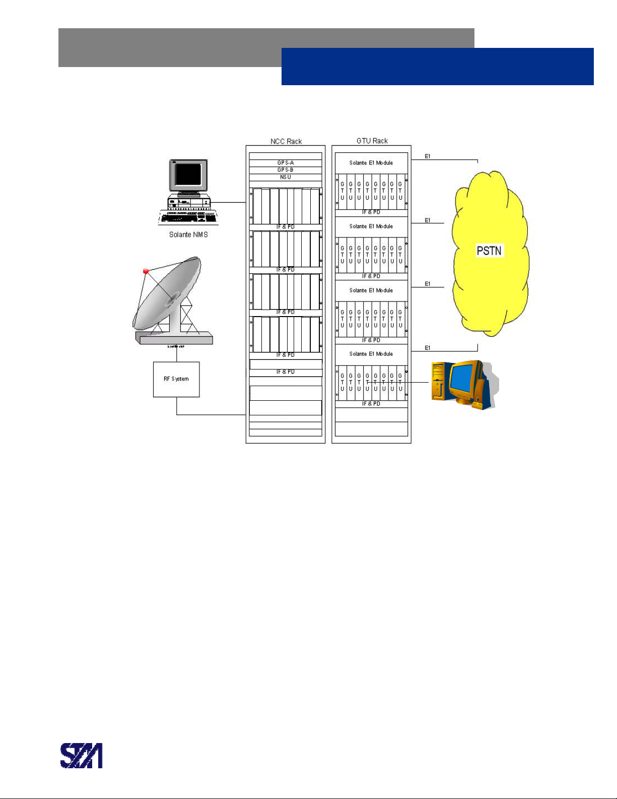
1.1.2 The Network Control Center - NCC
The NCC is the focal point for network control and a possible access to the PSTN. The NCC, at a
minimum, is composed of a Network Management System (Solante NMS), which controls all the
voice & data traffic processing, network configuration, alarms, event logs, etc.; a Network Control
Terminal (NCT), which can have multiple Subnetwork Control Terminals (SCT) or Solante
Network Controllers (SNC) and Solante Burst Demodulators (SBD); and the RF system (antenna,
RF unit, LNA/LNB, etc.)
1.1.3 SNC
The Solante Network Controller (SNC) unit is used in the Solante Network Control Center (NCC)
to transmit command and control messages via a Forward Order Wire (FOW) carrier to the
remote Solante units. See Figure 4. The FOW carrier is transmitted in the L-Band range for use
with RF uplink equipment.
The SNC is normally powered via an IF & Power Distribution unit at the NCC site and accepts an
external 10MHz Reference carrier and a Sync signal from the Network Synchronization Unit
(NSU).
The SNC communicates with the Network Management System (NMS) server using an Ethernet
interface. The SNC units can be configured and connected in redundant fashion. The Solante
system allows M:N redundancy; that is, M number of Backup SNC’s for N number of Primary
SNC’s. The SNC units are typically mounted in 19” wide indoor cabinets with 8-SNC’s per
chassis.
Each chassis has an IF & Power Distribution unit mounted just underneath in order to provide
power to the SNC’s and to combine the L-Band transmit signals into one common path. A rack
mounted Ethernet switch is used to connect all SNC units to a system LAN and then onto the
NMS. Generally, each SNC unit is paired with one or more Solante Burst Demod (SBD) units.
The SBD locks onto the SNC’s FOW carrier and reports back demodulator lock as well as
frequency offset. The SBD also receives inbound bursts from the remote & gateway Solante
units.
When the NCC is also the PSTN point of access, the same station includes one or more gateway
terminal units (GTU Rack), which provide interconnection with the PSTN and Internet back-bone.
The GTU is an indoor unit that communicates with the S-ODU remote station through the satellite
link, in one side, and provides connection with the PSTN on the other side of the network. The
Solante E1 Modules concentrate the E&M trunks from the GTU units and provide E1 trunk
interfaces for PSTN interconnection.
The NCC uses a common 10 MHz reference from a GPS unit to provide accurate frequency
reference to the system. The Network Synchronization Unit (NSU) distributes the 10 MHz

Solante S-ODU Model NGN-8100 Users Guide
STM Networks, Inc.
http://www.stmnetworks.com
Proprietary & Confidential
V2.0 6-2005 4
reference and generates network synchronization timing to all SCTs/SNCs. Figure 1.3 shows
NCC and GTU racks, and typical elements used in a Network Control Center.
GTUs at the NCC provide a communication link between the Alarm module at remote stations
and the Alarm Monitoring System. This provides the capability for multiple alarms from each
remote such as: Equipment door opened, AC Power failure, Battery charger failure, Fan Failure,
Low battery voltage, or Gate opened.
1.1.4 SBD
The Solante Burst Demodulator (SBD) unit is used in the Solante Network Control Center (NCC)
to receive the bursty inbound Return Order Wire (ROW) signals transmitted by the remote
stations. See Figure 4.
Messages passed on through the ROW channels include: Log-in, Status Responses, Call-
Request, and Clear-Confirm. It also receives the outbound FOW carrier as transmitted by its
respective Solante Network Controller (SNC) unit.
This is accomplished through the use of two distinct Receiver sections. The SBD sends
messages to its respective SNC to indicate demodulator lock status as well as frequency offset.
The SBD is normally powered via an IF & Power Distribution unit at the NCC site.
The SBD units can be configured and connected in redundant fashion. The Solante system
allows M:N redundancy; that is, M-number of Backup SBD’s for N-number of Primary SBD’s. The
SBD units are typically mounted in 19”-wide indoor cabinets with 8-SBD’s per rack shelf. Each
shelf has an IF & Power Distribution unit mounted just underneath in order to provide power to
the SBD’s and to divide the common L-Band receive signals for distribution to each SBD. A rack-
mounted Ethernet switch is used to connect all SBD units to a system LAN and then onto the
NMS and the SNC’s.

Solante S-ODU Model NGN-8100 Users Guide
STM Networks, Inc.
http://www.stmnetworks.com
Proprietary & Confidential
V2.0 6-2005 5
Solante E1 Module
IF & PD
Solante E1 Module
IF & PD
Solante E1 Module
IF & PD
Solante E1 Module
IF & PD
G
T
U
G
T
U
G
T
U
G
T
U
G
T
U
G
T
U
G
T
U
G
T
U
G
T
U
G
T
U
G
T
U
G
T
U
G
T
U
G
T
U
G
T
U
G
T
U
G
T
U
G
T
U
G
T
U
G
T
U
G
T
U
G
T
U
G
T
U
G
T
U
G
T
U
G
T
U
G
T
U
G
T
U
G
T
U
G
T
U
G
T
U
G
T
U
GPS-A
GPS-B
NSU
SCT-1
SCT-2
SCT-3
SCT-4
SCT-5
SCT-6
L-Band Dist.
L-Band Conv. - 1
L-Band Conv. - 2
10 Way IF Dist.
Satellite dish
RF System
NCC Rack GTU Rack
Solante NMS
E1
E1
E1
E1
Figure 3: Network Control Center (NCC) with NCC & GTU Racks (SCT type)
A
larm Monitoring System
Solante S-ODU Model NGN-8100 Users Guide
STM Networks, Inc.
http://www.stmnetworks.com
Proprietary & Confidential
V2.0 6-2005 6
S
N
C
S
N
C
S
N
C
S
N
C
S
N
C
S
N
C
S
N
C
S
N
C
S
B
D
S
B
D
S
B
D
S
B
D
S
B
D
S
B
D
S
B
D
S
B
D
S
B
D
S
B
D
S
B
D
S
B
D
S
B
D
S
B
D
S
B
D
S
B
D
S
B
D
S
B
D
S
B
D
S
B
D
S
B
D
S
B
D
S
B
D
S
B
D
Ethernet switch
Figure 4: Network Control Center (NCC) with NCC & GTU Racks (SNC/SBD type)
1.1.5 The Solante Gateway
The station that concentrates the voice/data traffic to and from the remote S-ODU stations and
interconnects with the PSTN is denominated Solante Gateway.
The Solante Gateway is composed of GTU units and Solante E1 Modules, all installed in the GTU
Racks. The RF system is typically equipped with antenna, LNB, and a High Power L-Band Block
Up Converter (BUC); but a regular 70 MHz Transceiver can also be used by the addition of a L-
Band/70 MHz Converter.
The GTU units support E&M trunks and the Solante E1 Modules are optional units to be used
when PSTN requires E1 interface. Similar to the S-ODU unit, the GTU also uses L-Band signals
to interface with the RF equipment.
Multiple GTU Racks can be used at the Solante Gateway station, increasing the number of trunks
available to support a demand for high traffic. Figure 5 shows a typical Gateway GTU rack and
station elements.
A
larm Monitoring System

Solante S-ODU Model NGN-8100 Users Guide
STM Networks, Inc.
http://www.stmnetworks.com
Proprietary & Confidential
V2.0 6-2005 7
Solante E1 Module
IF & PD
Solante E1 Module
IF & PD
Solante E1 Module
IF & PD
Solante E1 Module
IF & PD
G
T
U
G
T
U
G
T
U
G
T
U
G
T
U
G
T
U
G
T
U
G
T
U
G
T
U
G
T
U
G
T
U
G
T
U
G
T
U
G
T
U
G
T
U
G
T
U
G
T
U
G
T
U
G
T
U
G
T
U
G
T
U
G
T
U
G
T
U
G
T
U
G
T
U
G
T
U
G
T
U
G
T
U
G
T
U
G
T
U
G
T
U
G
T
U
Satellite dish
GTU Rack
E1
E1
E1
E1
High Power
BUC
LNB
Figure 5: Solante Gateway
1.2 The S-ODU Remote Station
The S-ODU unit is a multi-channel satellite terminal designed to provide voice services and a low
cost data link.
It is a cost-effective, reliable and extremely rugged satellite terminal designed for rural telephony
and data applications, offering a full range of services:
Voice, FAX and Data
•Low power consumption, even with multiple phone line support
•Configurable from two to eight lines in standard configuration
•Compact, all outdoor configuration; easy to install and rapid to deploy
Rugged ODU design; well suited to harsh rural environments
True modular design that makes it easy to expand to as many as 16 lines as traffic grows
Solante S-ODU Model NGN-8100 Users Guide
STM Networks, Inc.
http://www.stmnetworks.com
Proprietary & Confidential
V2.0 6-2005 8
Alarm system provides alarms to a central alarm monitoring facility
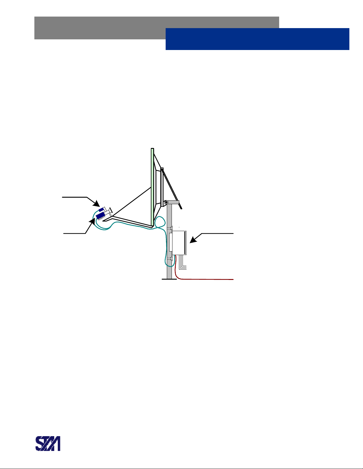
The S-ODU Remote Station is composed of three main electronic components, all in outdoor
packages (see Figure 6). These components are:
•Pole-mounted S-ODU (baseband) terminal (up to 8 channels per unit)
•Feed-mounted Block Up Converter (BUC)
•Feed-mounted Low Noise Block down converter (LNB)
Phone Lines
& LAN
S-ODU
LNB
BUC
Antenna
DC Power
Figure 6: Pole-Mounted, All-Outdoor S-ODU Remote Station
The S-ODU is typically powered by a Solar Panel and Battery Bank system. Optionally, an AC
power source with DC adaptor may be used. The BUC and LNB get power from the S-ODU.
From the LNB, the S-ODU receives, demodulates and processes incoming L-Band signals. On
the transmit path, it modulates baseband signals and transmits L-Band outgoing signals to the
BUC. Internal terminals have up to eight 2-wire loop-start telephone interfaces for easy
connection to regular telephones, payphones, or modems. An RJ-45 Jack connector provides
LAN connectivity (TCP/IP) for the Alarm Module connection.
The equipment is configured from a local console (Hyper Terminal), via RS232 (RJ-45 Jack
connector). Software code upgrades are downloaded via local console, or remotely from the NCC
(NMS).
A complete S-ODU Remote Station is composed of:
, Alarm Inputs,
Solante S-ODU Model NGN-8100 Users Guide
STM Networks, Inc.
http://www.stmnetworks.com
Proprietary & Confidential
V2.0 6-2005 9
•S-ODU terminal
•BUC (Block Up Converter; C or Ku-Band)
•LNB (Low Noise Block down converter; C or Ku-Band)
•Offset Rx-Tx Antenna System (C or Ku-Band)
•IFL (Inter-Facility Link cabling, for Tx and Rx signals)
•Solar Panel and Battery Bank System, or, AC/DC Power Adapter
1.2.1 The S-ODU Terminal
The S-ODU can be configured as a 4-Channel terminal (from 1 to 4 subscriber lines) or an 8-
Channel terminal (up to 8 subscriber lines), depending on the number of components mounted.
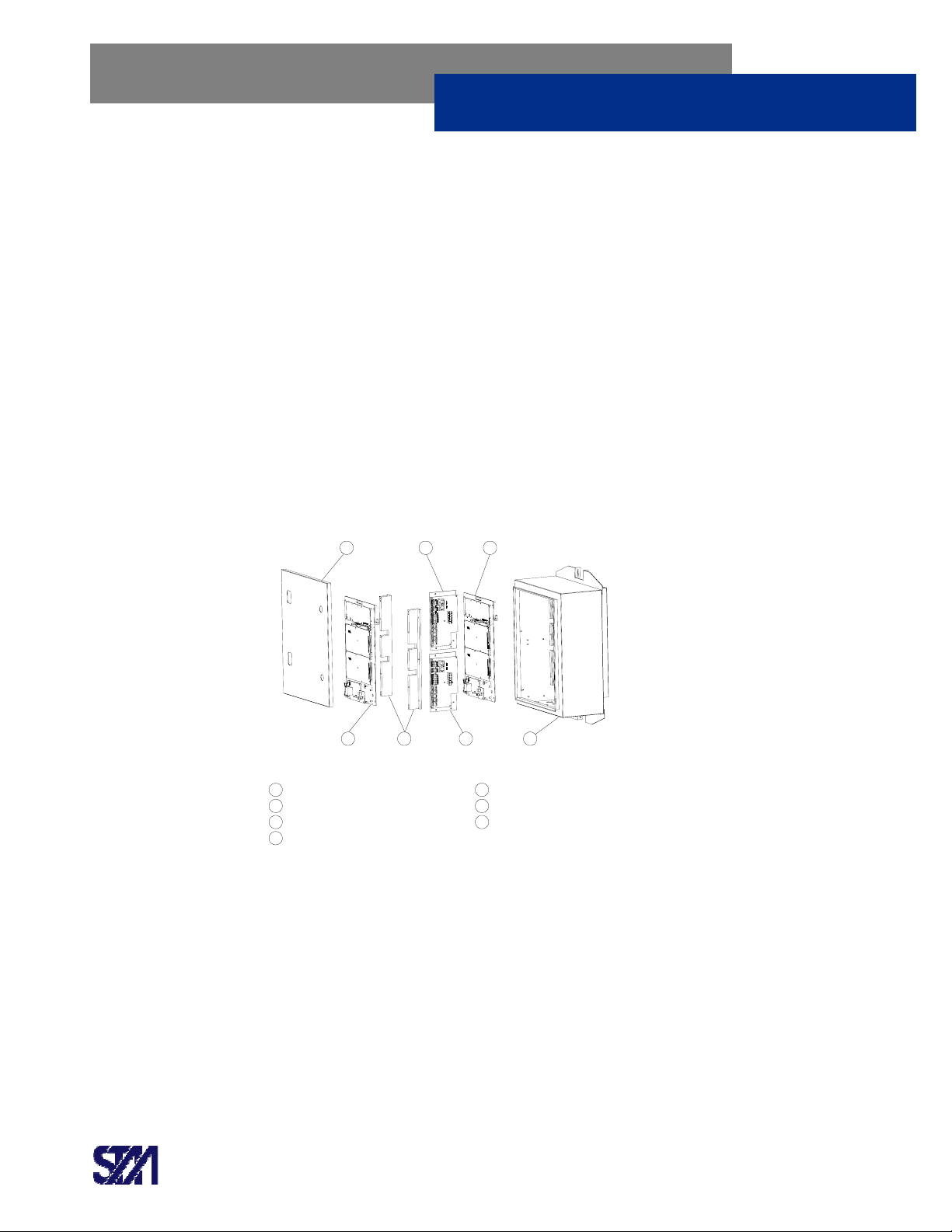
The Figure 7 shows a S-ODU prepared to have up to 8 lines.
12
3 45 6
7
1
2
3
4
5
6
7
Carrier Plate - Master Terminal
OCB Master (Outdoor Controller Board)
Carrier Plate - Slave Terminal
OCB Slave (Outdoor Controller Board)
Support Brackets
Chassis
Lid
Figure 7: S-ODU – Exploded View
The basic S-ODU configuration is a 4-Channel terminal. It includes only one Carrier Plate
(Master) and one OCB (items [1], [2], [6], and [7] – Figure 7). 2-Channel terminals are also
available.
When the S-ODU is expanded to an 8-Channel terminal, a second Carrier Plate (Slave) and OCB
are included in the basic configuration (items [3], [4], and [5] –Figure 7).

Solante S-ODU Model NGN-8100 Users Guide
STM Networks, Inc.
http://www.stmnetworks.com
Proprietary & Confidential
V2.0 6-2005 10
1.2.1.1 Chassis
The S-ODU chassis is made with steel, powder coated in light grey color (RAL 7035), and water
resistant (NEMA 4 Standard). A heat sink (aluminum extrusion) installed at the backside provides
heat transfer from the internal circuits to the outside of the chassis. Internal fan turns ON
automatically when temperature is higher then a certain value and equalizes the internal
temperature inside of the chassis.
Figure 8 shows the chassis and main dimensions.
Dimensions are in millimeters
Figure 8: S-ODU Chassis
1.2.1.2 Indicator LED’s
The Lid of the S-ODU chassis is a moveable cover that contains two transparent windows that
allow the viewing of Status LED’s of Master and Slave terminals. Labels identify the different LED
status. The OCB Master and OCB Slave units provide the LED’s and their functionalities.
Figure 9 shows both Master and Slave LED Windows and their locations.

Solante S-ODU Model NGN-8100 Users Guide
STM Networks, Inc.
http://www.stmnetworks.com
Proprietary & Confidential
V2.0 6-2005 11
LED Window - Master
LED Window - Slave
Figure 9: S-ODU – Master & Slave LED Windows
Both LED windows are identical, providing the same indications for Master and Slave terminals
respectively.
Solante S-ODU Model NGN-8100 Users Guide
STM Networks, Inc.
http://www.stmnetworks.com
Proprietary & Confidential
V2.0 6-2005 12
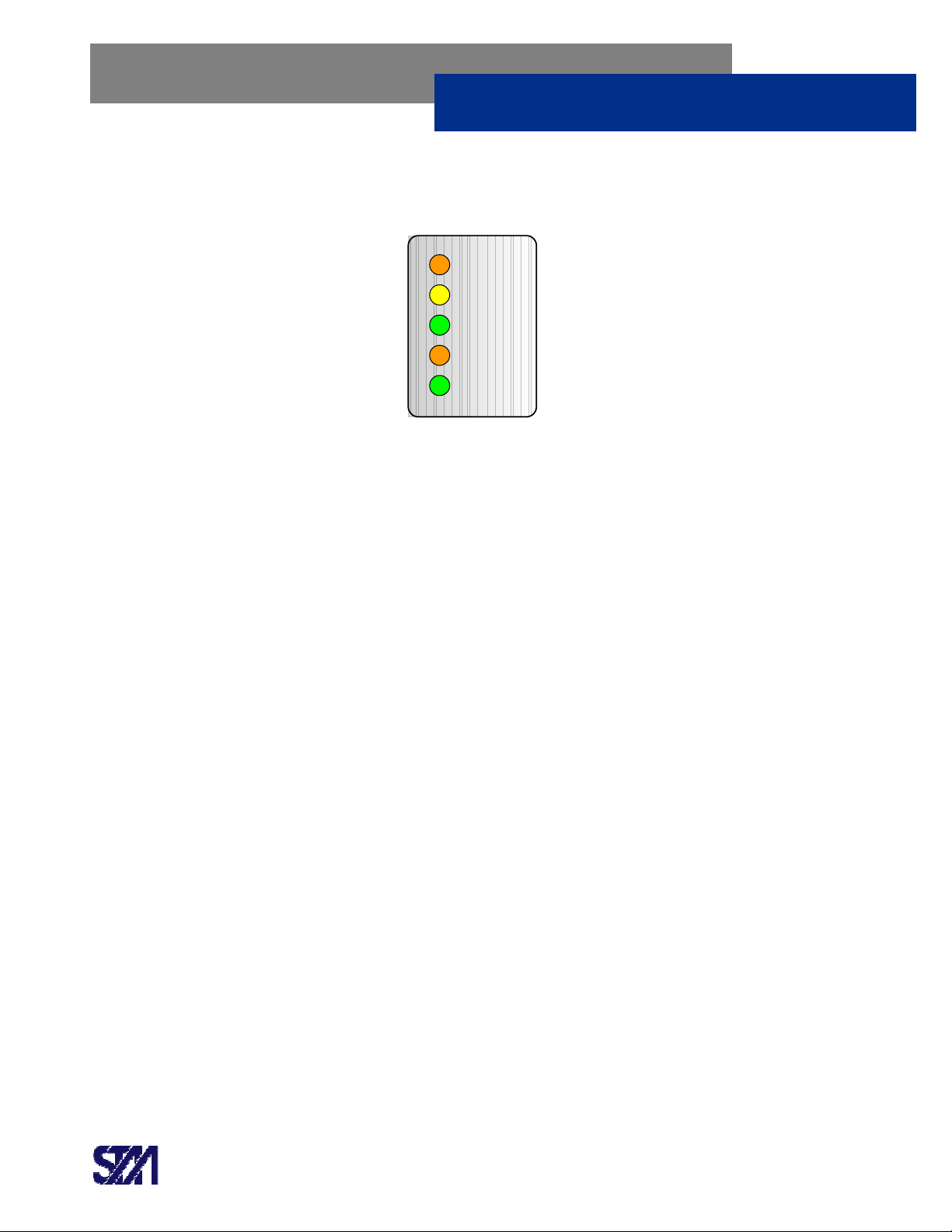
The Figure 10 shows a LED window, with respective labels and colors.
FAULT
LOCK
POWER
BATT
FAN
Figure 10: S-ODU – The LED Window
1.2.1.2.1 FAULT - Orange
It comes on Orange when the S-ODU is not locked on the FOW signal, or when the S-ODU or its
attached BUC is faulted, i.e.,
•The applied DC Voltage is out of nominal range
•The station is in DISABLED state
•The station is in WAIT_BUC_CONFIG state
•The station is in BUC_ABNORMAL state
1.2.1.2.2 LOCK – Yellow
It comes on Yellow when the S-ODU demodulator is locked to the FOW signal. It has 2 stages:
•Flashing Yellow when the station is locked to the FOW signal and ready to transmit, but
not logged in
•Solid Yellow when the station is locked to the FOW signal and is logged in
1.2.1.2.3 POWER – Green
Comes on Green when DC power (+24 VDC) is applied to the S-ODU
1.2.1.2.4 BATT – Orange
Comes on Orange when Battery Voltage is out of the nominal range.
Table of contents
Other STM Industrial Equipment manuals

STM
STM RFA Series Instruction Manual

STM
STM MINI-ROCKETBOX PLUS+ User manual

STM
STM REVOLUTION 2.0 User manual

STM
STM RX Series Instruction Manual

STM
STM ROCKETBOX 2.0 User manual

STM
STM ROCKETBOX User manual

STM
STM MINI-ROCKETBOX CANNA User manual

STM
STM ATOMIC CLOSER User manual

STM
STM ROCKETBOX Installation guide
Popular Industrial Equipment manuals by other brands

Nexen
Nexen AIR CHAMP FC-605 user manual

RIDGID
RIDGID 141 Operator's manual

Allen-Bradley
Allen-Bradley ControlNet Coax Tap 1786-TPR installation instructions

Wittenstein Alpha
Wittenstein Alpha SP+ operating manual

ProMinent
ProMinent CHLORINSITU IIa Maintenance Instruction

GUDEL
GUDEL ZP 3-5 V4 operating manual


