manuals.online logo
Brands
  1. Home
  2. •
  3. Brands
  4. •
  5. Strata
  6. •
  7. Welding System
  8. •
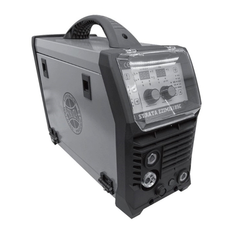
  9. Strata EZIARC 165 User manual

Strata EZIARC 165 User manual

This manual suits for next models

1

Other Strata Welding System manuals

Strata ADVANCETIG 200 User manual

Strata

Strata ADVANCETIG 200 User manual

Strata ADVANCECUT 75 User manual

Strata

Strata ADVANCECUT 75 User manual

Strata ADVANCECUT 45 User manual

Strata

Strata ADVANCECUT 45 User manual

Strata XM255PRO User manual

Strata

Strata XM255PRO User manual

Strata ADVANCEARC 160 User manual

Strata

Strata ADVANCEARC 160 User manual

Strata ADVANCEMIG 200 User manual

Strata

Strata ADVANCEMIG 200 User manual

Strata ADVANCETIG 200AC/DC User manual

Strata

Strata ADVANCETIG 200AC/DC User manual

Strata ADVANCEMIG 350 User manual

Strata

Strata ADVANCEMIG 350 User manual

Strata EZITIG 205DC User manual

Strata

Strata EZITIG 205DC User manual

Strata EZIMIG 205 User manual

Strata

Strata EZIMIG 205 User manual

Strata EZIMIG185C User manual

Strata

Strata EZIMIG185C User manual

Strata ADVANCEMIG 250 User manual

Strata

Strata ADVANCEMIG 250 User manual

Strata EZITIG 180 User manual

Strata

Strata EZITIG 180 User manual

Strata EZIMIG 200 User manual

Strata

Strata EZIMIG 200 User manual

Strata ADVANCECUT 65 User manual

Strata

Strata ADVANCECUT 65 User manual

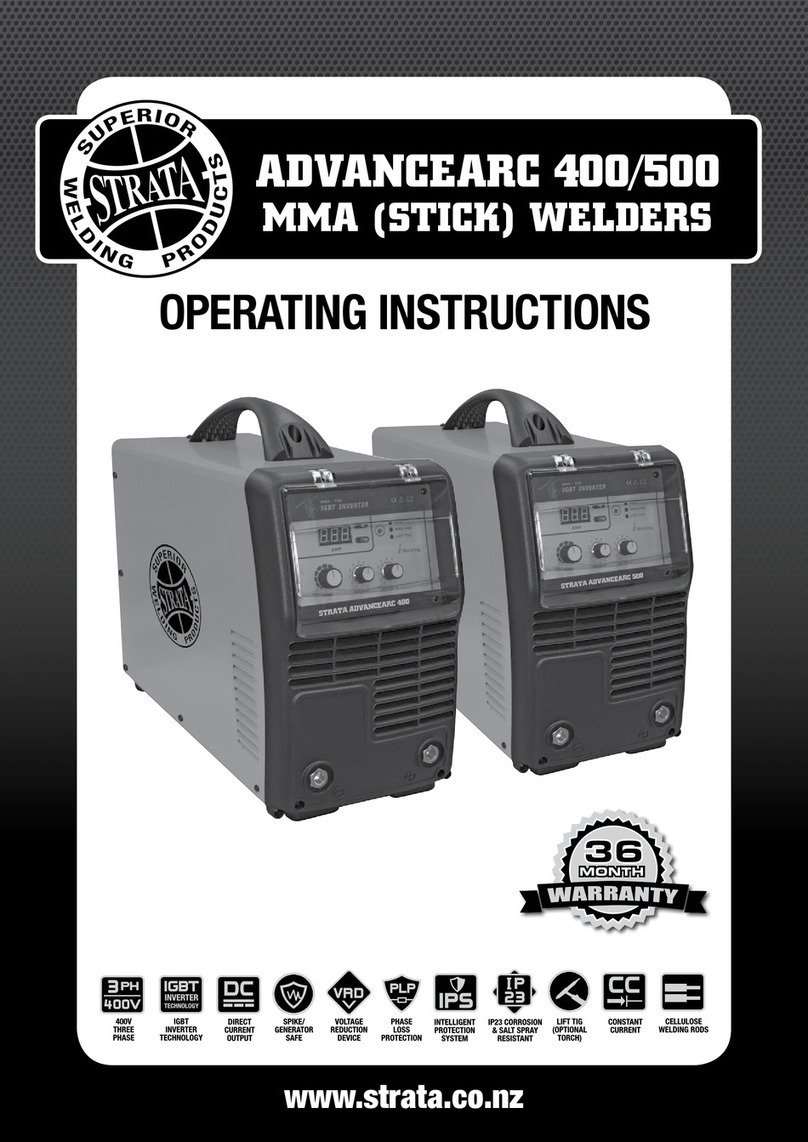
Strata ADVANCEARC 400 User manual

Strata

Strata ADVANCEARC 400 User manual

Strata ADVANCEARC 165 User manual

Strata

Strata ADVANCEARC 165 User manual

Strata ADVANCEMULTI205P User manual

Strata

Strata ADVANCEMULTI205P User manual

Strata ADVANCEMIG 255C User manual

Strata

Strata ADVANCEMIG 255C User manual

Strata ADVANCETIG 320AC/DC User manual

Strata

Strata ADVANCETIG 320AC/DC User manual

Strata EZIARC 160 User manual

Strata

Strata EZIARC 160 User manual

Popular Welding System manuals by other brands

Razorweld RAZORCUT45 instruction manual

Razorweld

Razorweld RAZORCUT45 instruction manual

Lincoln Electric Fleet 500 Operator's manual

Lincoln Electric

Lincoln Electric Fleet 500 Operator's manual

Migatronic OMEGA 220 quick guide

Migatronic

Migatronic OMEGA 220 quick guide

Magmaweld ID 300T DC user manual

Magmaweld

Magmaweld ID 300T DC user manual

Sealey POWERMIG Series instructions

Sealey

Sealey POWERMIG Series instructions

Defort 98291254 user manual

Defort

Defort 98291254 user manual

Hobart Welding Products AirForce 375 owner's manual

Hobart Welding Products

Hobart Welding Products AirForce 375 owner's manual

GF MSA 330 instruction manual

GF

GF MSA 330 instruction manual

Hakko Electronics FX-888D instruction manual

Hakko Electronics

Hakko Electronics FX-888D instruction manual

Abicor Binzel ABIPLAS WELD 100 W operating instructions

Abicor Binzel

Abicor Binzel ABIPLAS WELD 100 W operating instructions

EWM Taurus 355 Basic TDM operating instructions

EWM

EWM Taurus 355 Basic TDM operating instructions

Thermal Dynamics PakMaster 100 XL plus operating manual

Thermal Dynamics

Thermal Dynamics PakMaster 100 XL plus operating manual

Berner PLASMACUT 54 instruction manual

Berner

Berner PLASMACUT 54 instruction manual

Pro Spot PR-155 Assembly instructions

Pro Spot

Pro Spot PR-155 Assembly instructions

Forney 210 operating manual

Forney

Forney 210 operating manual

Thermal Arc 400S operating manual

Thermal Arc

Thermal Arc 400S operating manual

Lincoln Electric HANDYMIG 170I Operator's manual

Lincoln Electric

Lincoln Electric HANDYMIG 170I Operator's manual

GYS PROTIG 201 AC/DC Original instructions

GYS

GYS PROTIG 201 AC/DC Original instructions

manuals.online logo
manuals.online logoBrands
  • About & Mission
  • Contact us
  • Privacy Policy
  • Terms and Conditions

Copyright 2025 Manuals.Online. All Rights Reserved.

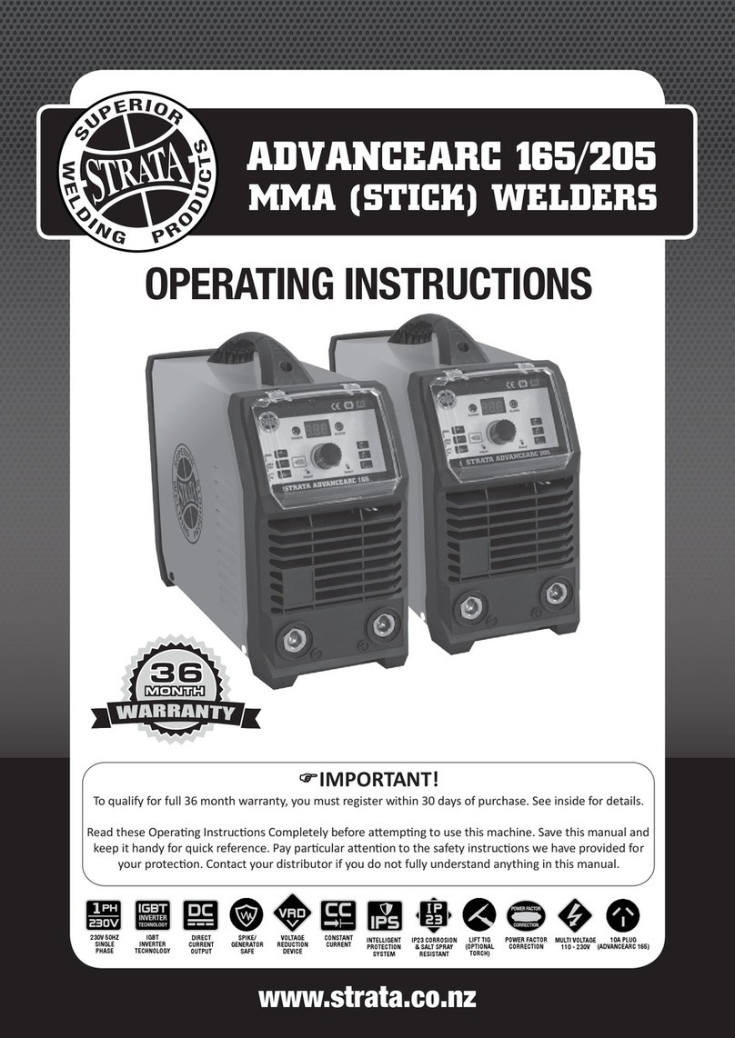
EZIARC 165/205
OPERATING INSTRUCTIONS
MMA (STICK) WELDERS
www.strata.co.nz
230V 50HZ
SINGLE
PHASE
IGBT
INVERTER
TECHNOLOGY
INTELLIGENT
PROTECTION
SYSTEM
DIRECT
CURRENT
OUTPUT
SPIKE/
GENERATOR
SAFE
IP23 CORROSION
& SALT SPRAY
RESISTANT
LIFT TIG
(OPTIONAL
TORCH)
CONSTANT
CURRENT
IMPORTANT!
To qualify for full 24 month warranty, you must register within 30 days of purchase. See inside for details.
Read these Operang Instrucons Completely before aempng to use this machine. Save this manual and
keep it handy for quick reference. Pay parcular aenon to the safety instrucons we have provided for
your protecon. Contact your distributor if you do not fully understand anything in this manual.
2www.strata.co.nz
EZIARC 165 • EZIARC 205
Congratulations on your new Strata product!
The Strata range from Euroquip uses latest technology design and engineering to produce
welding products that combine market leading value and features with durability. Designed
for discerning operators who seek professional results and product quality without the price
tag of a full professional setup. Design emphasis is placed on simple, functional design
and operation. Strata product is subject to stringent quality control and designed and
manufactured to NZ & Australian standards.
Common use of Strata products include:
• Light Engineering
• Automotive
• Home/hobby Engineering
• Farming
• Industrial Maintenance & Repairs
For industrial welding solutions, check out the Strata range from Euroquip:
www.strata.co.nz
Euroquip is a market leading provider of innovative power equipment solutions to a wide
range of industries across New Zealand and Australia. Key product categories are; welding
equipment, air compressors, power generators and cleaning equipment.
Euroquip’s slogan is ‘empowering industries’, find out more about the advantage Euroquip
brings at www.euroquip.co.nz.
Providing exceptional product support is a key component of Euroquip’s market leading
customer advantage focus. As part of this program, it is required for all products to be
registered with Euroquip to qualify for product support. Products not registered with Euroquip
are supported by a base 12 month warranty only. Spare parts and technical support will not
be available for an unregistered product outside of this base warranty period. If a Euroquip
dealer has not already registered your product, please register it online at www.euroquip.
co.nz. To request a physical registration form, please download one at www.euroquip.co.nz
under the ‘Contact Us’ tab.
4
ADVANCEARC 160 • ADVANCEARC 200
EZIARC 165 • EZIARC 205
MMA(STICK) WELDERS
The Advance Series of MMA (Stick) Welders offer the latest IGBT and PFC (Power Factor Correction)
technology for smart operators. Increased reliability, performance for harsh and demanding
voltage technology, giving you piece of mind when operating on generators or long extension cords.
• IGBT Inverter technology for smooth & stable welding output
• Damage resistant industrial casing with front panel protection
• Microprocessor control system for superior and dynamic arc
characteristics
• Lightweight & compact design, ideal for portable applications
• Automatic arc force, hot start & anti-stick for greater control
and ease of use
• Lift TIG welding operation for precision in aesthetically important
welding jobs (torch optional)
• High quality & over specified electronic components for
durability & reliability
EZIARC 165
DIMENSIONS: WEIGHT: INPUT POWER MAX. INPUT GENERATOR MMA CURRENT MMAO/C DUTY CYCLE: STANDARDS:MMA ROD MAX WELD
SUPPLY: CURRENT: CAPACITY: OUTPUT: VOLTAGE: SIZE: THICKNESS
390 x 146 x 278mm 2.6kg 230V AC 15A36A 8.5KVA 10A-160A 60%@114A EN60974-1:2012 1.6 - 4.0mm 8mm
50Hz
EZIARC 205
DIMENSIONS: WEIGHT: INPUT POWER MAX. INPUT GENERATOR MMA CURRENT MMAO/C DUTY CYCLE: STANDARDS:MMA ROD MAX WELD
SUPPLY: CURRENT: CAPACITY: OUTPUT: VOLTAGE: SIZE: THICKNESS
410 x 146 x 278mm 2.8kg 230V AC 15A46A 11KVA 10A-200A 70V 60%@130A EN60974-1:2012 1.6- 5.0mm 10mm
50Hz
70V
230V 50HZ
SINGLE
PHASE
IGBT
INVERTER
TECHNOLOGY
INTELLIGENT
PROTECTION
SYSTEM
DIRECT
CURRENT
OUTPUT
SPIKE/
GENERATOR
SAFE
IP23 CORROSION
& SALT SPRAY
RESISTANT
LIFT TIG
(OPTIONAL
TORCH)
CONSTANT
CURRENT
www.strata.co.nz
4
www.strata.co.nz
EZIARC 165 • EZIARC 205
Contents
Know Your Machine..........................................................5
Quick Start Guide..............................................................6
Available Parts & Accessories...........................................7
Wiring Diagram.................................................................8
Care & Maintenance..........................................................9
Electrodes.........................................................................9
Effects of MMA Welding Various Metals...........................10
Basic MMA Welding Guide..............................................11
Welding Techniques........................................................12
Other Knowledge & Resources........................................15
Troubleshooting..............................................................16
Safety..............................................................................18
Warranty.........................................................................23
5
www.strata.co.nz
EZIARC 165 • EZIARC 205
*Denotes more detailed explanation of function to follow.
1. Power Indicator. Lights when input power
connected and machine switched on
2. Error/ Overload Indicator*
3. Welding Current Control Knob
5. Negative (-) Welding Power Output
Connection Socket
4. Positive (+) Welding Power Output
Connection Socket
6. Welding Output Mode Switch.
Sets Power Source in MMA or Lift Tig Mode*
7. Digital Current Display Meter
1
2
3
4
6
5
7
Know Your Machine
5
www.strata.co.nz
EZIARC 165 • EZIARC 205
Know Your Machine
*Denotes more detailed explanation of function to follow.
1. Power Indicator. Lights when input power
connected and machine switched on
2. Error/ Overload Indicator*
3. Welding Current Control Knob
4. Positive (+) Welding Power Output
Connection Socket
5. Negative (-) Welding Power Output
Connection Socket
6. Welding Output Mode Switch.
Sets Power Source in MMA or Lift Tig Mode*
7. Digital Current Display Meter
1
2
3
4
6
5
7
6www.strata.co.nz
EZIARC 165 • EZIARC 205
Further Controls Explained
Overload/ Error Indicator
Lights when over voltage, over current or electrical
overheating (due to exceeding duty cycle) is detected
and protection is activated.
When protection is activated, welding output will be
disabled until the safety system senses the overload
has reduced sufficiently and indicator lamp goes out.
May also trigger if machine experiences an internal
power circuit failure.
Lift Tig Mode
Lift TIG is an arc ignition system for basic TIG weld-
ing that removes the need to ‘scratch’ start or strike
the tungsten on the work piece to start the arc, which
can have a negative effect on the weld quality due to
tungsten contamination.
Lift arc starting works by gently touching the tungsten
on the work piece and then lifting it off. The control
circuit will sense when the tungsten is removed from
the work piece and send a pulse of electricity through
the torch that will cause the TIG arc to initiate.
Tips & Tricks
Duty Cycle Rating
Welding duty cycle is the percentage of actual weld-
ing time that can occur in a ten minute cycle. E.g.
20% at 160 amps - this means the welder can weld at
160 amps for 2 minutes and then the unit will need to
be rested for 8 minutes.
All duty cycle ratings are based on an ambient air
temperature of 40°C with 50% humidity, which is the
international standard for such a rating. In an envi-
ronment with temperatures exceeding 40°C, the duty
cycle will be less than stated. In ambient temperature
less than 40°C, duty cycle performance will be higher.
7
www.strata.co.nz
EZIARC 165 • EZIARC 205
Electrical Connection
- The EZIARC 165 is designed to operate on a
15A 230V AC power supply.
- The EZIARC 205 is designed to operate on a
15A 230V AC power supply.
It is recom to use the Euroquip industrial
duty 15A extension lead, part number; 16895.
Operating Environment
Adequate ventilation is required to provide proper
cooling for the EZIARC 165/205. Ensure that
the machine is placed on a stable level surface where
clean cool air can easily flow through the unit. The
EZIARC165/205 has electrical components
and control circuit boards which may be damaged
by excessive dust and dirt, so a clean operating
environ-ment is important.
Basic Operation
1. ARC/ MMA Welding Operation
1.1 Connect the earth cable quick connector to the
negative welding power output socket (5) Con-
nect the earth clamp to the work piece. Contact
with the work piece must be firm. Contact with
clean, bare metal, with no corrosion, paint or
scale at the contact point.
1.2 Insert an electrode into the electrode holder and
connect the electrode holder and work lead to
the positive welding power output socket (4).
Quick Start Guide - Welder Installation
Note: This polarity connection configuration is valid for most
GP (General Purpose) MMA electrodes. There are variances to
this. If in doubt, check the electrode specifications or consult the
electrode manufacturer.
1.3 Connect the machine to suitable mains power
using the mains input power lead. Switch the
mains power switch to ‘on’ to power up the ma-
chine. Select MMA welding mode (7) using the
button (8).
1.4 Select the required output current using the
current control knob (3). You are now ready to
weld!
2. Lift TIG Operation
Note: Lift TIG operation requires an optional valve control TIG
torch, and argon gas cylinder.
2.1 Connect the earth cable quick connector to the
positive welding power output socket (4). Con-
nect the earth clamp to the work piece. Contact
with the work piece must be firm contact with
clean, bare metal, with no corrosion, paint or
scale at the contact point.
2.2 Insert TIG torch power connection into the nega-
tive welding power output socket (4). Connect
valve TIG torch gas line to the regulator, ensur-
ing all connections are tight.
2.3 Open gas cylinder valve and adjust regulator,
flow should be between 5-10 l/min depending
on application. Re-check regulator flow pressure
with torch valve open as static gas flow setting
may drop once gas is flowing.
2.4 Connect the machine to suitable mains power
using the mains input power lead. Switch the
mains power switch to ‘on’ to power up the ma-
chine. Select Lift TIG welding mode (6) using the
button (8).
2.5 Select the required output current using the cur-
rent control knob (3). You are now ready to
weld!
mended
8www.strata.co.nz
EZIARC 165 • EZIARC 205
Flat Position,
Down Hand Butt Weld
(Fig 1-11)
Flat Position,
Gravity Fillet Weld
(Fig 1-12)
Horizontal Position,
Butt Weld
(Fig 1-13)
Horizontal-Vertical
(HV) Position
(Fig 1-14)
Vertical Position,
Butt Weld
(Fig 1-15)
Vertical Position,
Fillet Weld
(Fig 1-16)
Overhead Position,
Butt Weld
(Fig 1-17)
Overhead Position,
Fillet Weld
(Fig 1-18)
Joint Preparations
In many cases, it will be possible to weld steel sec-
tions without any special preparation. For heavier
sections and for repair work on castings, etc., it will
be necessary to cut or grind an angle between the
pieces being joined to ensure proper penetration of
the weld metal and to produce sound joints.
In general, surfaces being welded should be clean
and free of rust, scale, dirt, grease, etc. Slag should
be removed from oxy-cut surfaces. Typical joint de-
signs are shown in Figure 1-19.
Open Square Butt Joint (Fig
1-19a)
Gap varies from1.6mm (1/16”)
to 4.8mm (3/16”) depending on plate thickness
Single Vee Butt Joint
(Fig 1-19b)
Not less than 45°
Single Vee Butt Joint (Fig
1-19c)
Not less than 70°
1.6mm (1/16”) max.
1.6mm (1/16”)
Double Vee Butt Joint (Fig
1-19d)
Not less than 70° 1.6mm (1/16”) max.
1.6mm (1/16”)
Basic MMA Welding Guide
9
www.strata.co.nz
EZIARC 165 • EZIARC 205
Lap Joint (Fig 1-19e)
Fillet Joint (Fig 1-19f)
Corner Weld
(Fig 1-19g)
Tee Joints
(Fig 1-19h)
Edge Joint
(Fig 1-19i)
Plug Welds
(Fig 1-19j)
MMAWelding Techniques
A Word for Beginners
For those who have not yet done any welding, the
simplest way to commence is to run beads on a piece
of scrap plate. Use mild steel plate about 6.0mm thick
and a 3.2mm electrode.
Clean any paint, loose scale or grease off the plate
and set it firmly on the work bench so that welding
can be carried out in the down hand position. Make
sure that the Work Lead/Clamp is making good elec-
trical contact with the work, either directly or through
the work table. For light gauge material, always clamp
the work lead directly to the job, otherwise a poor cir-
cuit will probably result.
The Welder
Place yourself in a comfortable position before begin-
ning to weld. Get a seat of suitable height and do as
much work as possible sitting down. Don’t hold your
body tense. A taut attitude of mind and a tensed body
will soon make you feel tired. Relax and you will find
that the job becomes much easier. You can add much
to your peace of mind by wearing a leather apron and
gauntlets. You won’t be worrying then about being
burnt or sparks setting alight to your clothes.
Place the work so that the direction of welding is
across, rather than to or from, your body. The elec-
trode holder lead should be clear of any obstruction
so that you can move your arm freely along as the
electrode burns down. If the lead is slung over your
shoulder, it allows greater freedom of movement and
takes a lot of weight off your hand. Be sure the insula-
tion on your cable and electrode holder is not faulty;
otherwise you are risking an electric shock.
Striking the Arc
Practice this on a piece of scrap plate before going on
to more exacting work. You may at first experience
difficulty due to the tip of the electrode “sticking” to
the work piece. This is caused by making too heavy
a contact with the work and failing to withdraw the
electrode quickly enough. A low amperage will accen-
tuate it. This freezing-on of the tip may be overcome
10 www.strata.co.nz
EZIARC 165 • EZIARC 205
20o
1.6mm (1/16”)
Striking an Arc
(Fig 1-20)
Arc Length
The securing of an arc length necessary to produce a
neat weld soon becomes almost automatic. You will
find that a long arc produces more heat.
A very long arc produces a crackling or spluttering
noise and the weld metal comes across in large, ir-
regular blobs. The weld bead is flattened and spatter
increases. A short arc is essential if a high quality
weld is to be obtained although if it is too short there
is the danger of it being blanketed by slag and the
electrode tip being solidified in. If this should happen,
give the electrode a quick twist back over the weld to
detach it. Contact or “touch-weld” electrodes such as
E7014 Stick electrodes do not stick in this way, and
make welding much easier.
Rate of Travel
After the arc is struck, your next concern is to main-
tain it, and this requires moving the electrode tip to-
wards the molten pool at the same rate as it is melting
away. At the same time, the electrode has to move
along the plate to form a bead.
Making Welded Joints
Having attained some skill in the handling of an elec-
trode, you will be ready to go on to make up welded
joints.
A. Butt Welds
Set up two plates with their edges parallel, as shown
in Figure 1-21, allowing 1.6mm to 2.4mm gap be-
tween them and tack weld at both ends. This is to
prevent contraction stresses from the cooling weld
metal pulling the plates out of alignment.
Plates thicker than 6.0mm should have their mating
edges bevelled to form a 70º to 90º included angle.
This allows full penetration of the weld metal to the
root. Using a 3.2mm E7014 Stick electrode at 100
amps, deposit a run of weld metal on the bottom of
the joint.
Do not weave the electrode, but maintain a steady
rate of travel along the joint sufficient to produce a
well-formed bead. At first you may notice a tendency
for undercut to form, but keeping the arc length short,
the angle of the electrode at about 20º from vertical,
and the rate of travel not too fast, will help eliminate
this.
Tack Weld
Butt Weld
(Fig 1-21)
Electrode
20o- 30o
Tack Weld
by scratching the electrode along the plate surface
in the same way as a match is struck. As soon as
the arc is established, maintain a 1.6mm to 3.2mm
gap between the burning electrode end and the par-
ent metal. Draw the electrode slowly along as it melts
down.
Another difficulty you may meet is the tendency, af-
ter the arc is struck, to withdraw the electrode so far
that the arc is broken again. A little practice will soon
remedy both of these faults.
The electrode is directed at the weld pool at about 20º
from the vertical. The rate of travel has to be adjusted
so that a well-formed bead is produced.
If the travel is too fast, the bead will be narrow and
strung out and may even be broken up into individual
globules. If the travel is too slow, the weld metal piles
up and the bead will be too large.