6www.strata.co.nz
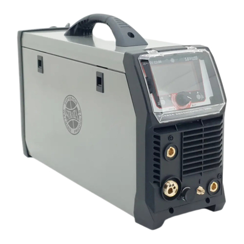
EZIMIG 200
Voltage/ Arc Force Display Meter
In MIG mode, displays welding voltage. In MMA
mode, displays arc force adjustment. The display me-
termodeisshownbytheindicator(9/10)thatislit.
Overload/ Error Indicator
Lightswhenovervoltage,overcurrentorelectrical
overheating(duetoexceedingdutycycle)isdetected
and protection is activated. When protection is acti-
vated, welding output will be disabled until the safety
system senses the overload has reduced sufficiently
andindicatorlampgoesout.Mayalsotriggerifma-
chine experiences an internal power circuit failure.
When protection is activated, welding output will be
disabled until the safety system senses the overload
has reduced sufficiently and indicator lamp goes out.
Mayalsotriggerifmachineexperiencesaninternal
power circuit failure.
Tips & Tricks
Duty Cycle Rating
Welding duty cycle is the percentage of actual weld-
ing time that can occur in a ten minute cycle. E.g.
20%at160amps-thismeanstheweldercanweldat
160ampsfor2minutesandthentheunitwillneedto
be rested for 8 minutes.
All duty cycle ratings are based on an ambient air
temperatureof40°Cwith50%humidity,whichisthe
internationalstandardforsucharating.Inanenvi-
ronmentwithtemperaturesexceeding40°C,theduty
cyclewillbelessthanstated.Inambienttemperature
lessthan40°C,dutycycleperformancewillbehigher.
MIG Voltage & Wire Speed Settings
The voltage control is essentially the power in the
welding arc that sets the heat. The wire speed feed
simply controls the rate at which the welding wire is
fedintotheweldpool.Foranyvoltagepositionset-
ting, there will be a specific corresponding ‘sweet
spot’ in the wire feeding speed that will give the
smoothest and most stable welding arc. The correct
wire feeding speed for a given voltage setting is af-
fected by welding wire type and size, shielding gas,
weldingmaterialand jointtype.It isrecommended
to set the welding voltage as desired and then slowly
adjust the wire speed until the arc is smooth and sta-
ble.Whenreachingthispoint,ifthepenetration/heat
inputistoomuch/notenough,adjustthevoltageset-
tingandrepeattheprocess.Iftheoperatorisnotable
to achieve a smooth and stable arc with the desired
heat input for the weld, it is likely that a change in wire
sizeand/orshieldinggastypeisrequired(assuming
allotherfactorsarecorrect).
Wave Control
ThissettingchangestheMIGwaveformtosimulate
changing the inductance of the welding circuit. In-
ductance controls the rate of the current rise and fall
astheweldingwirecontactstheworkpiece(knownas
ashortcircuit).Moreinductanceincreasestheshort
circuit time and decreases the short circuit frequency
rate. This causes a wider and more penetrating arc,
useful for thicker weld joints. Less inductance will
create a narrow more focused arc. This effect can also
be used to fine tune the arc to produce less splatter.
Wire speed, wire size and type, shielding gas will
all change the effect that the inductance setting has
ontheweldingarc.Inductancechangewillhaveno
practicaleffectonMIGspraytransferprocess(asop-
posedtoshortcircuitprocess),MMAorTIGwelding
process.
Arc Force Control
AnMMAweldingpowersourceisdesignedtopro-
duceconstantoutputcurrent(CC).Thismeanswith
different types of electrode and arc length; the weld-
ing voltage varies to keep the current constant. This
can cause instability in some welding conditions as
MMAweldingelectrodeswillhaveaminimumvoltage
they can operate with and still have a stable arc. Arc
Forcecontrolbooststheweldingpowerifitssenses
the welding voltage is getting too low. The higher the
arc force adjustment, the higher the minimum voltage
that the power source will allow. This effect will also
causetheweldingcurrenttoincrease.0isArcForce
off,10ismaximumArcForce.Thisispracticallyuse-
ful for electrode types that have a higher operating
voltage requirement or joint types that require a short
arc length such as out of position welds.
