Straumann Anthogyr XPERT UNIT 16400X User manual
fr - Manuel d’utilisation
en - User manual
de - Gebrauchsanweisung
es - Manual de uso
it - Manuale d'uso
pt - Manual de utilização
nl - Gebruikershandleiding
zh - 使用说明
- ar
hu - Felhasználói útmutató
pl -
ro - Manual de utilizare
bcdefghij®

22
TABLE OF CONTENTS
Implantology motor
1. DESCRIPTION OF SYMBOLS 22
2. INTRODUCTION 23
3. AREA OF USE 23
4. INDICATIONS AND CONTRAINDICATIONS 23
5. SAFETY 24
6. DESCRIPTION 27
7. CONNECTIONS - INSTALLATION 28
8. INITIALISING THE CONSOLE 30
9. USE 31
10. PARAMETER MANAGEMENT 35
11. CLEANING, DISINFECTING AND STERILISATION 35
12. CONDITIONS OF USE AND STORAGE 36
13. WARRANTY 36
14. MANUFACTURER'S RESPONSIBILITIES 37
15. REGULATIONS 37
16. ANOMALIES AND FAULTS 37
17. TROUBLESHOOTING OPERATIONS BY THE USER 39
18. TECHNICAL SAFETY INSPECTION BY AGENCY 39
19. ELECTROMAGNETIC COMPATIBILITY 39
20. REFERENCE 41
1. DESCRIPTION OF SYMBOLS
n Alternating current hFragile iTransport in standing position; with the top
facing the direction of the arrow
C Type B equipment. ZStore in a dry place Q Sterile device
E Warning : Follow the operating
instructions JMaximum permitted stack
load 50 kg WDo not reuse, single-use device
mProtective earth kHandle with care xDo not place in domestic dustbin
A Manufacturer VDevice expiry date tDo not tilt
MClass IIa device in compliance
with European directive
93/42CEE O Device manufacturing lot
number IP4x Protection against foreign bodies > 1 mm
fThermodisinfectable device P Serial number IPx6 Protection against strong water spurts in all
directions
gSterilisable at a specific tem-
perature DHumidity limit D Follow the operating instructions.
XDo not use if the packaging is
damaged EAtmospheric pressure limit ù Do not sterilise
YProtect from light N Commercial reference num-
ber of the device Refer the instruction manual/brochure
k Permissible temperature
limits Risk of crushing - Do not touch rotating parts with your finger when the pump is on
MD Medical Device

a®- en- USER GUIDE
23
frendeesitptnlzh
arhuplro
2. INTRODUCTION
You have just acquired your new dental implantology motor, XPERT UNIT®.
Anthogyr congratulates you for your choice and thanks you for your confidence in this product.
In order to complete and sustainable benefit from this product, it is recommended that you read this user manual first and perform the
recommended inspection and maintenance tasks.
This Anthogyr product is to be used exclusively with the accessories provided by Anthogyr (micromotor, pedal, power supply cable). The
use of any other accessories is prohibited.
This equipment is compatible with most of the surgical contra-angles and handpieces available on the market. However, the technical
features (torque and speed) of this product can only be used with the Anthogyr Mont Blanc®contra-angle.
It is mandatory to use the irrigation lines supplied by Anthogyr. The use of any other irrigation lines can create malfunctioning for which
Anthogyr cannot be held responsible in any way.
It is essential to take all the precautions mentioned with the symbols Ein order to keep the equipment in optimal condition with total safety.
The manufacturer reserves the right to make changes or improvements in the equipment as a result of from new technical developments.
This does not give retrospective rights to equipment already installed.
To ensure that the Anthogyr product is operational at all times and to maintain it in good working condition, adhere to the maintenance,
disinfection, and sterilisation instructions (see section “11 - Cleaning, disinfecting, and sterilisation”).
Only Anthogyr technicians or those trained by Anthogyr are authorised to repair the medical device (Check your equipment control
parameters after maintenance operations; it is possible that it has been set to default values).
These instructions may not by copied and distributed without the prior written consent the Anthogyr .
The user is under obligation to :
→Use only products that are free of defects.
→Protect patients, third parties, and oneself from any danger.
→Avoid any contamination to spread through the product.
The user is responsible for checking the operating safety and the condition of the equipment before each use.
While using the product, it is essential to adhere to the national legal provisions and particularly :
→Provisions applicable to connecting and starting the MD.
→Provisions applicable to safety at work.
→Provisions for prevention of accidents.
3. AREA OF USE
3.1. PATIENT POPULATION AND CONDITION TO BE TREATED
Patients in need for dental, maxillofacial or implant surgery.
3.2. INTENDED USER
Dental surgeon or Oral and maxillofacial surgeon.
3.3. INTENDED USE
XPERT UNIT®motors are intended to drive dental handpieces equipped with instruments to cut hard and soft tissues in the mouth and to
insert dental implants, with a control of the tool speed and irrigation supply.
The device also provides an indication of the torque applied at implant placement when used in combination with Anthogyr Mont Blanc®
contra-angle handpieces.
An interface (screen or pedal) allows the user to adjust and memorize different settings for the parameters of speed, torque, pump flow,
and reduction gear.
4. INDICATIONS AND CONTRAINDICATIONS
4.1. INDICATIONS
XPERT UNIT®motors are indicated to perform surgeries in patients requiring a dental surgery or dental implant placement.
4.2. CONTRAINDICATIONS
Patient presenting contra-indications to an oral surgical procedure.
24
5. SAFETY
5.1. RESIDUAL RISKS AND SIDE EFFECTS
Surgical motors misuse (error in the selection or tuning of predefined surgical sequence, rotation speed or direction, pre-selection of
operating limits) may lead to patient injury.
5.2. WARNING SIGN
In order to avoid any physical or material damage, this document divides the safety instructions into three levels of danger.
5.3. SAFETY INSTRUCTIONS
5.3.1 - External interference
The equipment is certified to comply with the electromagnetic compatibility standards currently in force.
5.3.2 - Electrical connection
However, the user must ensure that no further risk is created by electromagnetic disturbance.
To avoid disturbing the proper functioning of the electromagnetic equipment, it is recommended to adhere to the stipulated distances
among devices (“see section 19. ”Electromagnetic compatibility”).
ATTENTION
This equipment is not designed to withstand shocks from an electric defibrillator.
WARNING
ELECTRIC SHOCK / ELECTROCUTION
Non-compliant electrical connection
Compulsorily check that the power supply voltage is identical to that whitch is indicate on the control box.
Check the power supply cable before every use.
Never insert or pull the plug from the wall socket with wet hands.
DANGER
To avoid any risk of an electric shock, this equipment must only be connected to a power supply network equipped with protective
earthing.
WARNING
E
Warning sign
Indicates a hazardous situation that may cause material damage or from minor to moderate injuries.
ATTENTION
Indicates a hazardous situation that may cause serious/fatal injuries.
WARNING
Indicates maximum danger created by a situation that may immediately cause serious/fatal injuries.
DANGER

a®- en- USER GUIDE
25
fr
en
de
es
it
pt
nl
zh
ar
hu
pl
ro
5.3.3 - Environment
5.3.4 - Use of the device
5.3.5 - Storage conditions
5.3.6 - Peristaltic pump
5.3.7 - Micromotor and micrometer cable
Recommended conditions : protect from moisture and store at room temperature.
Keep away from sunlight, sparks and other sources of ignition.
Temperature : from -20 °C to +70 °C.
Air humidity level : from 5% to 95%.
Incompatible materials : acids and other solvents.
ATTENTION
Do not operate the pump if the irrigation line is blocked or closed by a clamp.
Always place the fluid to be pumped above the pump, in order to ensure optimal operation of the latter.
Always keep the pump head rollers and all moving parts clean and free of contamination and debris.
ATTENTION
Do not open the guard when the pump is rotating.
Do not touch the rotating parts with your fingers when the pump is in operation.
ATTENTION
Refer to the instructions for use supplied with the micromotor and/or micromotor cable to familiarise yourself with all safety and usage
aspects.
ATTENTION
Never attempt any repair alone.
DANGER
Do not tilt the device.
Ensure that the cords do not obstruct the free movement of persons.
Do not use the device near ionising radiation.
The device must be connected to a nearby wall socket that is easily accessible. The required power cords include a plug that can bear at
least 125% of the rated current of the device.
Use a maximum impedance network of 4Ω.
ATTENTION
Do not use this product in premises with explosion hazards.
Do not expose the equipment to water splashes or water mist.
In order to avoid risk of electric shock, short-circuit, or emission of dangerous substances, do not insert metalic objects into the equip-
ment.
DANGER
ELECTROCUTION
Accidental penetration of liquid in the fuse box.
Before every use, check and ensure impermeability of containers of liquids. If any liquid should penetrate the equipment, do not touch it
and immediately disconnect the power supply cable from the electricity network. Make sure that the surface of the equipment is
completely dry before reconnecting the power supply cable.
DANGER
Do not move the device while in use.
We strongly recommend that the torque be limited so as not to exceed the manufacturers’ recommendations for the instrumentation
used. This is to limit the risk of injury and deterioration of instruments.
ATTENTION
Once the servicing work is completed, switch off the device. Unplug it from the electrical mains in the event of prolonged non-use.
WARNING
26
5.3.8 - Hygiene and maintenance
5.3.9 - Malfunction
In the event of abnormal operation (flickering screen, noisy pump motor, vibrating micromotor) :
→Immediately stop using the device.
→Try to locate or eliminate the problem with the help of the descriptive document (see section 16. "Anomalies and faults").
→If it is not possible to locate or eliminate the problem with the help of the descriptive document, switch off the device and call the
Anthogyr After-Sales Service.
Anthogyr After-Sales Service - Tel. : +33 (0)4 50 58 50 53 - contact@anthogyr.com
Do not use any spray directly on the medical device to clean it; the use of wipes is preferred.
ATTENTION
Refer to the instructions for use supplied with the micromotor and/or micrometer cable to familiarise yourself with all maintenance
aspects.
ATTENTION
Sterilisable products are supplied in non-sterile condition and are required to be decontaminated and sterilised before the first use as
well as immediately after each use.
DANGER
Never attempt any repair alone.
DANGER

a®- en- USER GUIDE
27
frendeesitptnlzh
arhuplro
4 5
6. DESCRIPTION
N° Name
1 Peristaltic pump
2 ON/OFF Button (I/O)
3 Power socket 220V / 110V
4 Touch screen
5 Connector for micromotor cable
Front
N° Name N° Name
A Wireless pedal G Micromotor
B Console H Bracket
C Irrigation line I Micromotor protective casing
D Adapter J Console dust cover
E Power cord K Clips for irrigation line
F Micromotor cord L Micromotor support
3
1 2
Rear
BA
LJ K
C
D
E
I
H
F
G

28
7. CONNECTIONS AND INSTALLATION
It is extremely important to familiarise yourself with all safety instructions before installation and use of the device (see section 5.
"Safety").
Refer to the instructions for use supplied with the micromotor and/or micromotor cable to familiarise yourself with all safety,
maintenance and usage aspects.
7.1. MAINS CONNECTION
Use only the power cable supplied by the manufacturer.
Do not forget to verify that the supply voltage is exactly same as the one mentioned on the
control cabinet and the power switch is in the Position 0.
7.2. CONNECTION / DISCONNECTION OF THE MICROMOTOR
To connect, align the red dot of the micromotor socket to the red dot of the connector on the face of the console and clipper :
Technical Specifications
Dimensions
Console (w x d x h) 243 x 222 x 102 mm
Pedal (l x d x h) 280 x 170 x 70 mm
Micromotor (Ø x l) Ø23 x 115 mm
Micromotor cable (l) 2 m
Console 2.5 kg
Weight Pedal 1 kg
Micromotor 110 g
Micromotor cable 110 g
Electrical
Input power supply from 100 to 240 V (50-60 Hz)
Power consumption 200 to 300W
Input fuse Ø5 x 20 - T5A 250 V
Classification Console IP4X
Pedal IPX6
Electrical classification Class I according to IEC 60601-1
Type B
Bluetooth classification
Group 1
Class B
FCC ID QOQBGM111
IC 5123A-BGM111
Micromotor Rotation speed 100 - 40000 rpm
Motor connection Model with light: TYPE 4-short
Model without light: TYPE 1-short
Peristaltic pump
Maximum flow rate at 100% with Anthogyr line 120 ml/min
Pump pipe Øext Ø7 mm
Pump pipe Øint Ø4 mm
CE classification Directive 93/42/CEE Class IIa conforming to rule 9 for console / pedal / micromotor
cable / micromotor class I conforming to rule 1 for the micromotor
mount / clips / bracket
Display N.cm Torque (Newton.centimetre)
rpm Speed (revolutions per minute)
E
E
E

a®- en- USER GUIDE
29
frendeesitptnlzh
arhuplro
To disconnect,
pull the mobile part of the connection in the direction of the arrow.
Do not try to disconnect the micromotor cable by pulling on the
cable!
7.3. CONNECTION / DISCONNECTION OF A CONTRA-ANGLE ON THE MICROMOTOR
Engage the contra-angle on the motor nose.
Rotate the contra-angle on the motor nose until it is positioned correctly.
On the contra-angle opening, a soft 'snap' sound confirms that the positioning is correct.
7.4. POSITIONING OF THE BRACKET AND THE BAG
Insert the bracket in the rear of the
console.
The positioned bracket must not turn by
itself.
Suspend the bag of physiological liquid on the bracket.
7.5. PLACEMENT OF THE IRRIGATION LINE IN THE PERISTALTIC PUMP
Part to be inserted in the pump
E ✓
Exit Input
21 3
The LED micromotor (Ref XP311L) is not compatible with LED contra-angles.
ATTENTION
30
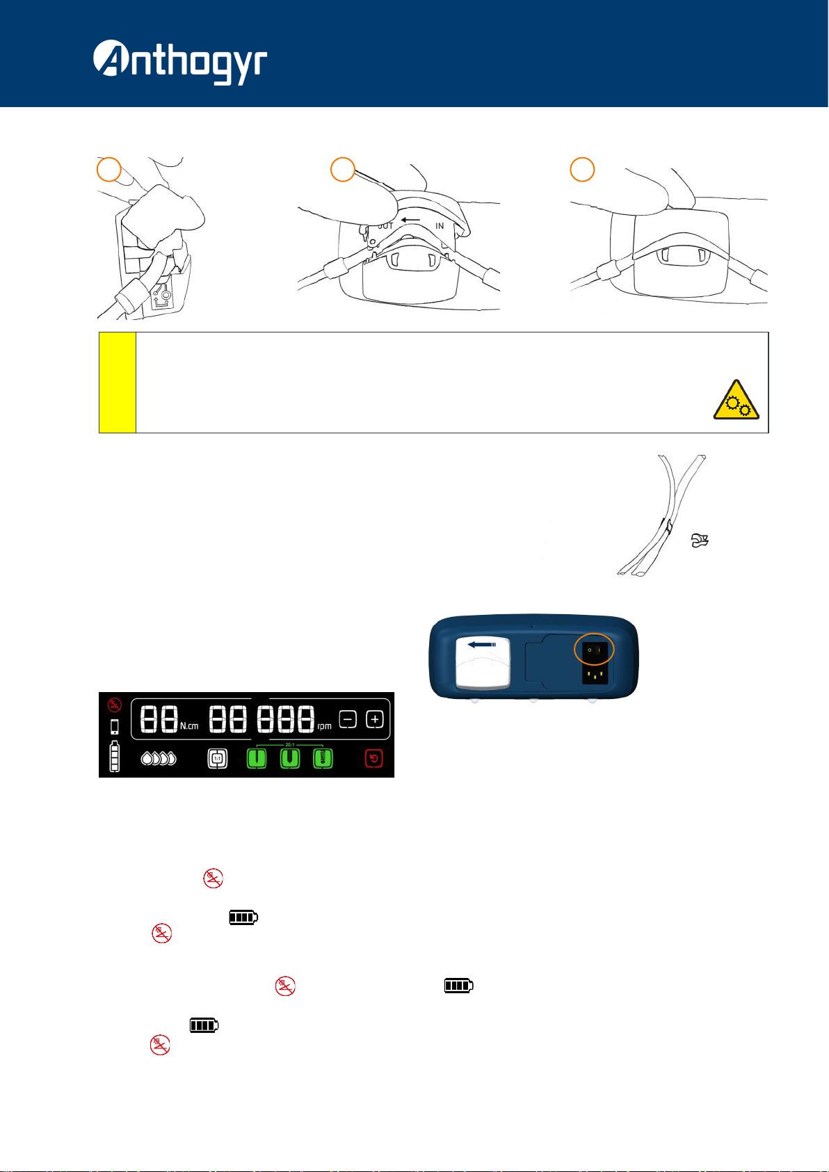
7.6. PLACEMENT OF IRRIGATION CLIPS
Place the irrigation clips on the micromotor cable at regular intervals (between 15-20 cm).
Position the irrigation line along the micromotor cable by inserting it into the clips.
8. INITIALISING THE CONSOLE
8.1. POWER-UP
Set the power switch to position I
At startup, all the symbols on the screen light up and the device emits a
beep.
* The code Er02002 at startup means there is an anomaly with the date and time. The date and time synchronise automatically with the mobile app when you
are connected.
8.2. WIRELESS PEDAL CONNECTION
8.2.1 - On first use
At unit startup, if the symbol is displayed, the pedal is on standby.
Press on the pedal lever to exit standby mode.
→As soon as the symbol is displayed, the pedal is ready to be used.
→If the symbol remains lit up, the pedal needs to be pared with the console (see section 8.2.3).
8.2.2 - When using daily :
At startup, after a few seconds, the symbol disappears and the symbol appears.
If the symbol remains activated after startup, press on the pedal lever exit the standby mode.
→As soon as the symbol appears, the pedal is ready to be used.
→If the symbol remains activated, proceed to pair the pedal with the console (see section 8.2.3).
4 5 6
Do not operate the pump, if the irrigation line is blocked or closed by a clamp.
Always place the fluid to be pumped above the pump, in order to ensure optimal operation of the latter.
Always keep the pump head rollers and all moving parts clean and free of contamination and debris.
Do not open the guard when the pump is rotating.
Do not touch the rotating parts with your fingers when the pump is in operation.
ATTENTION

a®- en- USER GUIDE
31
fr
en
de
es
it
pt
nl
zh
ar
hu
pl
ro
8.2.3 - How to pair the pedal with the console
1 - Press on the pedal lever.
2 - Press the three green buttons on the screen at the same time.
3 - The symbol flashes until pairing is complete (time to achieve pairing = about 30 sec)
4 - Press the two end buttons on the pedal.
5 - A beep at the console confirms the pairing : the symbol disappears and the symbol
is displayed.
→If the symbol remains activated, see section 16.“Anomalies and faults”
8.2.4 - How to place the pedal in extended standby.
If you do not plan to use your motor for an extended period of time (> 30 days), or if you wish to
transport it by air, placing the pedal in extended standby mode is recommended.
To do this, just press on the three pedal buttons simultaneously.
The persistent display of the symbol on the screen confirms that the pedal is on standby.
To exit standby mode, just press on the pedal lever (see section 8.2.1).
9. USE
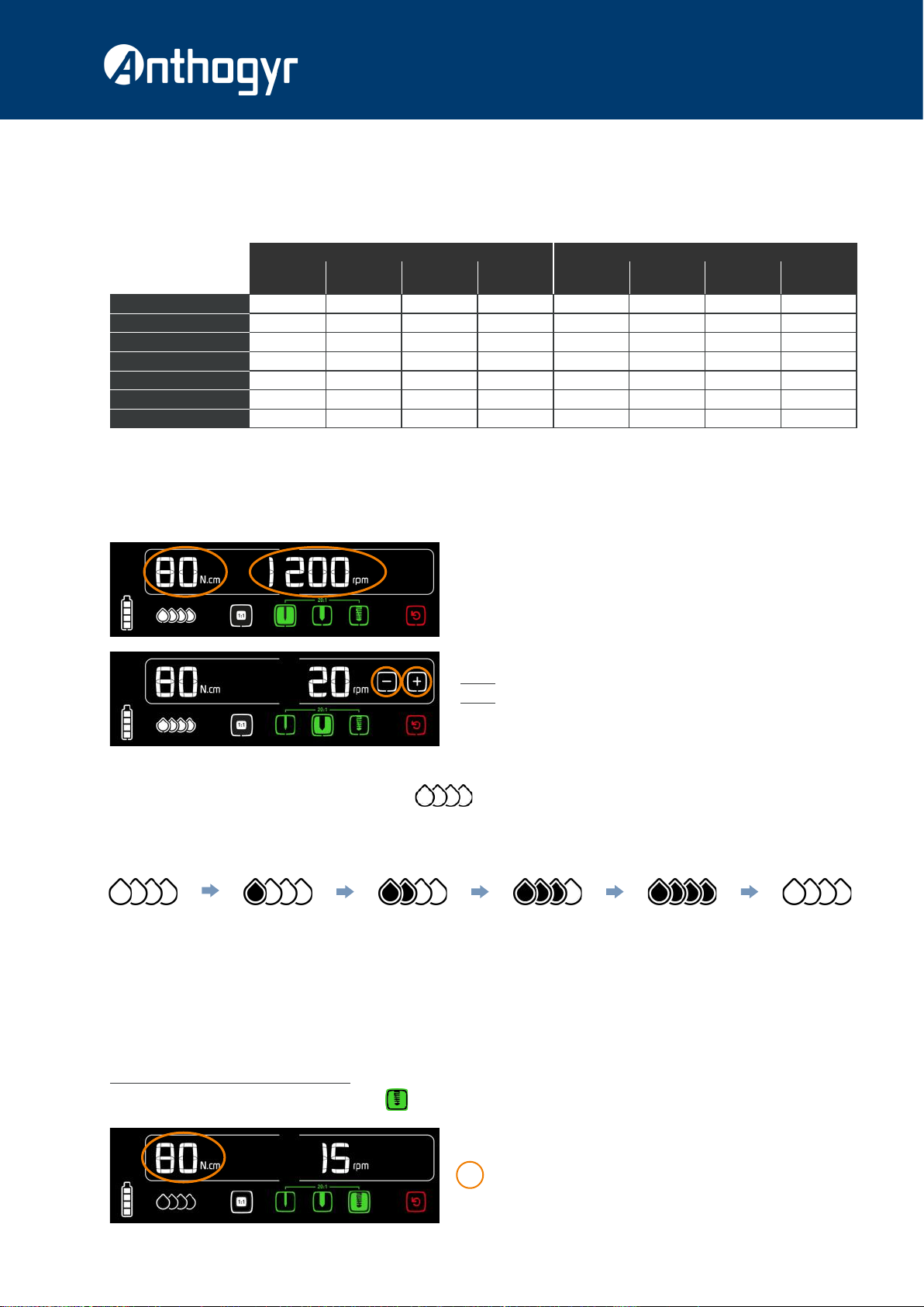
9.1. DEFINITION OF THE DISPLAY
* the coloured square indicates the current program.
Programmed maximum
torque (N.cm)
Programmed maximum
speed (rpm)
Charge level of the
pedal battery
Reverse operation20 :1 Implantology sequence
Drilling / tapping / screwing
1:1 ProgramIrrigation flow rate
Pump
0% 25% 50% 75% 100%
Battery
0% 25% 50% 75% 100%
*
32
9.2 PARAMETERS OF PROGRAMS (FACTORY SETTING)
To select a program on the screen, press on the symbol of the desired program. For navigation to the pedal between the implantology
sequence programs, see section. 9.5. “Use of pedal”
At startup, the "drilling" program is active. The program parameters can be changed by following the instructions given below.
* Setting franges rom 5 to 80 N.cm. These values are valid only for Mont Blanc®contra-angles (10400X-XL / 16400X-XL). With these contra-angles, the
accuracy of torque is ± 10% for 5 to 80 N.cm.
9.3. SETTING SPEED / TORQUE / FLOW RATE VALUES
9.3.1 - Setting rotation speed and maximum torque
1 - Press on the parameter to be changed (speed or torque).
2 - The parameter starts flashing and the +/- buttons appear.
3 - Adjust the value of the parameter with the + or –buttons.
4 - Press on the parameter to validate. The parameter stops flashing.
5 - The parameter automatically stops flashing after 5 seconds and the
set value is saved.
NOTE 1 : The value of the parameter is permanently saved for the program.
NOTE 2 : You cannot operate the pedal during the setting of parameters.
9.3.2 - Setting irrigation flow rate
For setting the irrigation flow rate, press on the symbol
Each press increases the flow rate by 25% (display of an additional drop).
At 100%, pressing the symbol sets the irrigation flow rate to 0%.
To cut off the irrigation and reset to a given flow rate, use the pedal’s ON / OFF function of. (See section 9.5 “Use of the pedal”).
9.4. DISPLAYING THE LAST TORQUE REACHED
The XPERT UNIT®motor allows you to validate the tightening torques to be saved. These torques will be exported with the XPERT UNIT®
mobile app and used on the web portal.
Displaying and saving the tightening torques
When the motor has stopped in tightening mode, ( button lit up), the torque displayed is the maximum torque programmed (image
A).
In normal mode In reverse mode
20 :1
Drilling
20 :1
Tapping
20 :1
Screwing 1:1 Ratio 20 :1
Drilling
20 :1
Tapping
20 :1
Screwing 1:1 Ratio
Speed (rpm) 1200 20 15 40 000 2000 40 30 15 000
Torque * (N.cm) 80 80 80 80 80 80 80 80
Direction of rotation right right right right left left left left
Pump 100% 100% 0% 100% 0% 0% 0% 0%
Display of torque NO YES YES NO NO YES YES NO
Display of speed YES YES YES YES YES YES YES YES
Beep / / / / YES YES YES YES
0% Press 25% Press 50% Press 75% Press 100% Press 0%
A

a®- en- USER GUIDE
33
fr
en
de
es
it
pt
nl
zh
ar
hu
pl
ro
When the motor is rotating, the torque displayed on the screen is the instantaneous torque (Image B).
When the motor stops, the last torque remains displayed for 30 seconds, before the display returns to the maximum torque programmed
(Image A).
* To re-display the last torque, long press on the torque shown on the setpoint screen (Image A).
The last torque obtained is displayed with the active patient number. (Image C).
When long pressing on the value of the torque, the value of the torque is saved (a confirmation beep is heard).
To return to the setpoint screen without saving the torque value with the patient number, press
Patient numbering
To make it easier to identify the saved torques, you can enter the patient number corresponding to the saved torques. This information
will appear in the data exported with the mobile app.
To edit the patient number, press on the PXX area. This area will start flashing and the +and -buttons will appear.
Once adjusted, press on the PXX area to validate or wait 3 seconds without doing anything.
To return to the setpoint screen without saving the torque value with the patient number, press
You may also edit the patient number after the setpoint screen (Image A) by pressing if this is already lit.
To return to the setpoint screen without saving the torque value with the patient number, press
IMPORTANT : EACH TIME THE PEDAL IS PRESSED, THE LAST TORQUE OBTAINED IS ERASED.
IMPORTANT : EACH TIME THE EQUIPMENT IS TURNED ON, THE PATIENT NUMBER RESETS TO P01.
B
C

34
9.5. USE OF THE PEDAL
Description of pressing different buttons and lever
9.6. BACKUP POWER FOR THE WIRELESS PEDAL
This symbol represents the charge level of the pedal battery.
When the battery charge level has reached 25%, at least one day of use of the pedal will remain. The device beeps and the symbol
flashes, indicating the need to recharge soon (see instructions below).
When charge level of the battery reaches 0%, the device will beep every 30 seconds and it will not be possible to use the motor.
Recharge according to the following instructions.
9.7. RECHARGING THE PEDAL BATTERY
Connect the charging adapter to the pedal with the connector located at the rear of the pedal.
Connect the adapter to the mains to power it up.
On screen, symbol is activated to indicate that charging is in progress.
When this symbol is displayed, the battery is fully charged.
→The motor can be used in a normally during the charging of the pedal battery.
9.8 STOPPING THE MOTOR
At the end of the dental procedure :
→Set the switch to position 0.
→Remove the tool fixed to the contra-angle.
→Remove the bottle or the bag of physiological liquid from the bracket.
→Detach the drill from the irrigation line coming from the bottle or the bag of
physiological liquid.
→Remove the clips for irrigation lines.
→Disconnect the contra-angle from the micromotor.
→Lay the micromotor on the micromotor support.
Pressing lever (D) Variation in the rotation speed of the micromotor
Pushing lever (D) Illumination of the light for 3 seconds
Short pressing on the left button (A)Irrigation ON / OFF (the flow rate set on the screen is preserved)
Long pressing on the left button (A)Startup of the pump at the maximum flow rate without the micromotor
rotating (rinsing function)
Short pressing on the middle button (B)Activation / deactivation of reverse mode
Long pressing on the middle button (B)Torque reduced by 5 increments
Short pressing on the right button (C)Moving from one sequence to the next
Long pressing on the right button (C)Torque increased by 5 increments
A B
C
D
a®- en- USER GUIDE
35
fr
en
de
es
it
pt
nl
zh
ar
hu
pl
ro
9.9 MEDICAL DEVICE LIFECYCLE
If used in a proper manner, the micromotor and its cable have a lifecycle corresponding to 250 cleaning and sterilisation cycles; the pedal
has a lifecycle corresponding to 5 years of use.
However, these indications are not a warranty because wear may appear prematurely, depending on how the device is maintained (see
section 11. “cleaning, disinfection and sterilization).
10. PARAMETER MANAGEMENT
ACTIVATION / DEACTIVATION OF AUDIO WARNINGS
List of audio warnings
*To activate/deactivate audio warnings, press
on the button REVERSE on illumination of the
console.
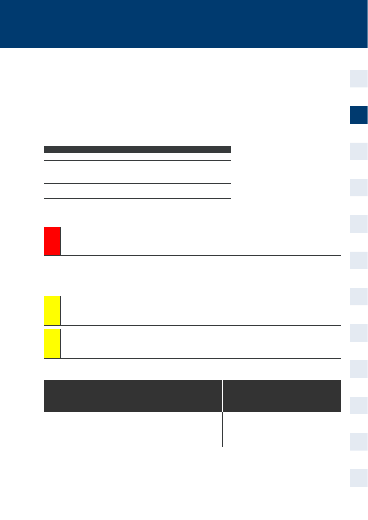
11. CLEANING, DISINFECTING AND STERILISATION
Use disinfectant products in accordance with the instructions given by their manufacturers.
The Medical devices that can be sterilised can withstand a temperature between 134 °C and 137 °C for 3 or 18 minutes in accordance with
current laws of the country.
Remove the irrigation line and place it in a safety container meant for soiled medical items (single-use irrigation line).
OVERVIEW OF MAINTENANCE
Sterilisable products are supplied in non-sterile condition and must be decontaminated and sterilised before the first use as well as
immediately after each use.
DANGER
Single-use Thermodisinfectable Disinfectable by wipes and
non-sterilisable Disinfectable by wipes and
sterilisable (no immersion)
Disinfectable by immersion
(ultrasound) and
sterilisable
W e ù g g
Bags of physiological
liquid
Irrigation lines
Screen Protection
Micromotor protection
casing
Micromotor
Contra-angle
Console
Pedal
Micromotor cable
Micromotor
Bracket
Motor support
Clips for irrigation line
Contra-angles of the
Mont Blanc®
Do not use any spray directly on the medical device to clean it; it is preferable to use wipes.
ATTENTION
Refer to additional instructions on the micromotor and micromotor cable for more information.
ATTENTION
Description Can be deactivated
Weak battery NO
Operating in reverse NO
Programmed maximum torque reached YES*
Validation of sending data to a connected device YES*
Pairing of the pedal to the console NO
Complete integrity at console startup NO

36
CLEANING-DISINFECTION-STERILISATION CYCLE
Throw away single-use consumables
12. CONDITIONS OF USE AND STORAGE
13. WARRANTY
24 MONTH WARRANTY
→This device is guaranteed for parts and labour against any manufacturing defect for a period of 24 months from the date of invoice.
→This warranty does not apply to part wear.
→Any modification or addition to the product without the express consent of the company Anthogyr will nullify this warranty null and void.
→The warranty will lapse in case of non-observance of the technical instructions provided with all our devices.
→Anthogyr cannot be held responsible for damages and consequences resulting or possibly resulting from normal wear and tear,
incorrect use, cleaning or maintenance, non-observance of the instructions regarding use or connection, scaling or corrosion, impurities
in the water supply system, or chemical or electrical influences that are unusual or non-compliant with the user manual, maintenance
and assembly instructions of Anthogyr and other instructions of manufacturers.
→The transport expenses for return of goods for repair at Anthogyr are to be borne by the customer, even if the repair is done under
warranty.
→The warranty covers shipping costs for return of the items to the customer.
→In order to consider warranty claims, please keep a copy of the invoice or a copy of the delivery note along with the device.
→The Medical devices must be returned in cleaned and sterilised condition in a closed bag with proof of passage to the autoclave, the
authentic coloured indicator, with a letter stating the reason for return.
→The renewal of spare parts is assured for 7 years after the commercial stoppage of the product.
W
E
PACKAGING
SURGICAL
PROCEDURE
CLEANING WITH
WIPE
WASHER/
THERMAL
DISINFECTOR
NON-
SUBMERGEABLE
INSTRUMENTS
ASSEMBLY
LUBRICATION*
(cable + micromotor)
DRYING RINSING
ULTRASONIC TANK
RINSING
PRE-DISINFECTION
SUBMERGEABLE
INSTRUMENTS
SELECTION OF
INSTRUMENTS
PURGING THE
IRRIGATION LINES
AND CLIPS
STERILISATION VIA
AUTOCLAVE
* Only for the contra-angles
Conditions of use and operation
Temperature +10°C to +40°C (50°F to 104°F)
Relative humidity 15 to 80 %
Atmospheric pressure 70 to 106 kPa
Conditions of use and storage
Temperature -20°C to +70°C (-4°F to 158°F)
Relative humidity 5 to 95 %
Atmospheric pressure 70 to 106 kPa
ù
e
g
6
5
8
7
9
10
11
12
5a 5b
1
2 3
4a
4b

a®- en- USER GUIDE
37
fr
en
de
es
it
pt
nl
zh
ar
hu
pl
ro
14. MANUFACTURER'S RESPONSIBILITIES
The present instruction does not replace instructions for peripheral products.
Anthogyr reserves the right to modify the device and/or the user manual without prior notice.
The following points, if not followed, will avoid the responsibility of Anthogyr :
→All the recommendations of Anthogyr must be respected during installation (voltage supply, electromagnetic environment, etc.)
→The device must be used in an electrical installation conforming to the regulations in force.
→The use of this device must be restricted to the operation for which it has been designed.
→No subsequent modification, extension or settings , may be made by a third party or any other person.
→Opening and repairs may only be carried out by persons trained by Anthogyr or authorized persons.
→Only original Anthogyr spare parts may be used.
→The product must be used in accordance with the assembly, service and maintenance instructions.
→All the instructions contained in this document must be followed.
15. REGULATIONS
According to the ISO11498 and ISO7494 standards , the device comes under the category of dental treatment devices.
This medical device is classified as IIa according to European directive 93/42/EC.
This equipment is manufactured in conformity with the currently applicable standard pursuant to IEC60601-1.
This equipment has been designed and manufactured according to an ISO 13485 quality assurance system.
As electrical and electronic equipment, disposal of the product must be carried out as per a specialised collection, removal, and recycling
or destruction chain (particularly in the European market, with reference to the directive no. 2002/96/CE dated 23/01/2003).
When the product reaches its end of life, we recommend that you contact your dental equipment reseller to find out, how to proceed.
The box, wireless pedal, micromotor, and the micromotor cable include components that must be treated as non residential waste.
Put the pedal in a special container meant for the treatment of e-waste.
16. ANOMALIES AND FAULTS
This part is intended to help the user in case of problems.
In the event of abnormal operation (flickering screen, noisy pump motor, vibrating micromotor), immediately stop using the device and
call the Anthogyr After-Sales Service. If it is not possible to locate or solve a problem with the help of this descriptive document, or if the
malfunction signals still remain active, switch off the device and call the Anthogyr After-Sales Service. Do not attempt to disassemble the
console, the motor or the pedal.
16.1. ERROR CODES AND MEANINGS
It is possible to remove the error message from the screen by pressing on it. In the event of a major problem, the console restarts. If the
error message reappears, please contact the Anthogyr After-Sales Service.
x It is prohibited to throw the pedal into a domestic bin.
ATTENTION
Never attempt to carry outrepairs alone.
DANGER
Error code Description of the fault Possible solutions
Er 02 001 Torques as well as the system parameters (setting, error file) are no longer saved.
Check the different parameters of the sequences (speed, torque, flow rate) The assembly can
still be used.
Contact the Anthogyr
After-Sales Service
for more
information.
Er 02 002
The date and time are incorrect
The date and time can be updated using the mobile application.
Attention : if the date and time are not correct, the retrieval of information using the mobile applica-
tion will be inaccurate.
Er 05 001 The motor is still usable, but the pump runs the risk of not operating.
Er 02 004
The screen encounters operating problems
The micromotor/pedal/micromotor assembly can still be used safely with the pedal to complete the
treatment in progress. If the problem per-
sists, do not use the
motor / pedal / micro-
motor any longer.
Contact the Anthogyr
After-Sales Service
for more infor-
mation.
Er 02 005
The touch bar encounters operating problems
The micromotor/pedal/micromotor assembly can still be used safely with the pedal to complete the
ongoing care.
Er 02 006
Er 02 007 Update the console software using the mobile application
Er 04 006 Overheating of the micromotor.
Let the micromotor be idle for 30 minutes to 1 hour so that it cools.

38
If it is not possible to locate or solve the problem with the help of different descriptive documents, switch off the device and call the
Anthogyr After-Sales Service.
Depending on the error code, it is also possible to use the mobile application to send information to the Anthogyr After-Sales Service.
16.2. MALFUNCTION
*The use of "compatible" or "adaptable" lines may generate malfunctions. The use of irrigation lines supplied by Anthogyr is preferable.
If it is not possible to locate or eliminate the problem with the help of above different descriptive documents, switch off the device and call
the Anthogyr After-Sales Service.
Anthogyr After-Sales Service
Tel. : +33 (0)4 50 58 50 53
contact@anthogyr.com
E
Malfunction Probable causes Possible solutions
The micromotor does not rotate
The micromotor is not connected to the console
The micromotor is jammed
The pedal is not detected and no longer allows
interaction with the console.
Ascertain that the cable is connected to the cabinet
Mount a contra-angle with a tool of large diameter and
try to rotate it
See pedal problems below.
The pedal is not detected by the console
The pedal is not (or longer) paired with the
cabinet / the pedal is of
The battery is completely discharged
Proceed to the pairing of the pedal (see section 8.2.3)
Turn on the pedal (see section 8.2.1)
Put the pedal for recharging
The battery symbol indicates that re-
charging is not taking place (no activa-
tion)
The battery does not get charged
The charger is defective or assembled incur-
rectly
Contact the After-Sales Service
After setting the pedal battery for charg-
ing, the battery symbol is always con-
stantly and the level has remained at
25%
The battery does not get charged Contact the After-Sales Service
No spray or low flow rate, or leakage
problem
The flow rate of the pump is 0% or too low
The irrigation line has not been placed correctly
The irrigation line is defective or has been
pinched*
Adjust the flow rate of the pump on the screen
Check the positioning of the line in the pump.
Check the mounting direction of the line in the pump
Change the irrigation line
Use the Anthogyr irrigation line
The tool of the contra-angle does not
turn
Bad connection of the tool in the contra-angle
The contra-angle has been damaged
The motor is jammed
Check the tool and its placement
Change of contra-angle
Check the integrity of the motor, if the cable is con-
nected properly to the console
The screen does not light up
The power to the device has been switched off
The fuses have blown
The power socket is defective
The differential circuit breaker of the electrical
installation is OFF
The power cord is defective
The electronic card and/or the screen are out
of service
Ascertain that the console is attached properly to the
mains and/or that the (I/O) button is on position I
Replace the fuses (see section §17)
Change the wall socket
Reset the differential circuit breaker of the electrical
installation
Replace the power cord
Contact After-Sales Service
Error code Description of the fault Possible solutions
Er 02 005 - Er 02 006
Er 02 007 - Er 04 001
Er 04 002 - Er 04 003
Er 04 004 - Er 04 005
Er 04 006 - Er 04 007
Er 04 008 - Er 04 009
Er 04 010 - Er 04 011
Er 04 012 - Er 05 001
The electronics have encountered a hardware or software failure
Do not use the motor/
pedal/micromotor any
longer
Return to the Antho-
gyr After-Sales Ser-
vice is mandatory

a®- en- USER GUIDE
39
fr
en
de
es
it
pt
nl
zh
ar
hu
pl
ro
17. TROUBLESHOOTING OPERATIONS BY THE USER
Inspecting and replacing of fuses.
→Switch off the console with the ON / OFF button (I/O).
→Unplug the power cord from the wall socket.
→Unplug the power cord from the console.
→Remove the fuse box located between the (I/O) switch and the power socket with a flat screwdriver.
→Take out the two fuses.
→Check the status of the fuses and, if necessary, change them (SPT Ø5x20-T5A-250 V with a breaking capacity of 1500A)
→Replace the two fuses in the fuse box.
→Replace the fuse box.
18. TECHNICAL SAFETY INSPECTION BY AGENCY
The XPERT UNIT®motor for implantology and dental surgery must undergo technical inspection by a regular agency at least once every
three years (unless current country legislation indicates otherwise).
The technical safety inspection must be carried out by an agency authorised by Anthogyr.
Anthogyr After-Sales Service
Tel. : +33 (0)4 50 58 50 53
contact@anthogyr.com
19. ELECTROMAGNETIC COMPATIBILITY
→This product requires special precautions to be taken regarding electromagnetic compatibility. It must be installed and initialised
according to the instructions given in the section 7."Connections/ and installation".
→Certain types of mobile telecommunication devices, such as mobile phones, are likely to interfere with this product. Therefore, it is not
recommended to use them during the use of this devices.
→The separation distances recommended in this paragraph must therefore be followed.
→This product must not be used near or on another device. If this cannot be avoided, it is necessary to check prior to use its proper
operation prior to use under the conditions of use.
→The use of accessories other than those specified or sold by Anthogyr as replacement parts, can result in increased radiation or
decreased immunity of this product.
E
→Visual inspection of all the external parts
→Measurement of leakage current of the device (console + pedal)
→Measurement of leakage current at the patient side
→Measurement of electrostatic discharge (ESD)
→Inspection of motor operation
→Inspection of pedal operation
→Inspection of pump operation
→Inspection of screen operation
→Internal visual inspection, if there is external damage, signs of
overheating, or abnormal noise or failures are observed.
Do not attempt to disassemble the control console, the motor or the control pedal.
DANGER

40
Directives and declaration of the manufacturer - Electromagnetic radiations
The XPERT UNIT®motor is intended to be used in the environment specified below.
It is advisable for customer or user of the XPERT UNIT®motor to ensure that it is used properly in such an environment.
Radiation test References of the standards Compliance
RF radiations CISPR 11 Group1 Class B
Speaker port : Group 1 Class B 10 m
30MHz - 230MHz = 30dBµV/m
230MHz - 1GHz = 37dBµV/m
Input power : 240Vac / 50Hz
Limits : Group 1 Class B
0.15MHz to 0.5MHz
66 to 56dBµV QP / 56 to 46dBµV AV
0.5MHz to 5MHz
56dBµV QP / 46dBµV AV
0.15MHz to 0.5MHz
60dBµV QP / 50dBµV AV
Harmonic radiation IEC 61000-3-2 220Vac 50Hz access : Limit Class A
Voltage fluctuation / flicker IEC 61000-3-3 230Vac 50Hz access : PST <1 PLT > 0.65
The motor XPERT UNIT®uses RF power only for its internal functions. Therefore, its RF radiation ise very low and is not likely to cause any
interference in nearby electronic equipment.
The XPERT UNIT®motor is suitable for use in all premises, including domestic premises and those directly connected to the low-voltage public
electricity supply network feeding buildings for domestic use.
Directives and declaration of the manufacturer - Electromagnetic immunity
The XPERT UNIT®motor is intended to be used in the environment specified below.
It is advisable for customer or user of the XPERT UNIT®motor to ensure that it is used properly in such an environment
Radiation test References of
the standards Compliance Electromagnetic environment - directives
Off-peak period of power,
short interruptions and
voltage fluctuations in
electrical power supply input
lines
IEC 61000-4-11
AC power supply : 240Vac @50Hz
0% UT: 0.5 cycle at 0 °, 45 °, 90 °, 135 °, 180 °,
225 °, 270 °, 315 ° (criterion A)
0% UT: 1 cycle - Single phase at 0 ° (criterion
A)
70% UT: 25 cycles - Single phase at 0 °
(criterion A)
0% UT: 250 cycles (criterion C)
It is advisable that the quality of the electricity supply
network be that of a typical commercial or hospital
environment.
If user of the XPERT UNIT®motor requires continu-
ous operation during interruptions in the electricity
supply network, it is recommended to power the
XPERT UNIT®motor from an uninterrupted power
supply or a battery.
Conducted RF disturbances IEC 61000-4-6 Effective 3V from 150kHz to 80 MHz (criterion
A)
It is advisable that portable and mobile RF communi-
cation devices not be used near any part of the XPERT
UNIT®motor, including cables, closer than the rec-
ommended separation distance calculated from the
equation applicable to the frequency of the transmit-
ter.
Recommended separation distance : d = 1.2 √P
Electrostatic discharges IEC 61000-4-2 ±8kV at the contact
±2kV, ±4kV, ±8kV, ±15kV in the air (criterion B)
It is advisable that the floor be made of wood, con-
crete or ceramic tiles. If floors are covered with syn-
thetic materials, then the relative humidity should be
at least 30%.
Fast transient bursts IEC 61000-4-4 AC power supply : ±2kV (100Hz) / 240Vac @50Hz
DC power supply : ±2kV (100Hz)
Line input / output : ±1kV (100hz) (CriterionB)
It is advisable that the quality of the electricity supply
network be that of a typical commercial or hospital
environment.
Magnetic field at the electrical
power supply network fre-
quency (50/60 Hz) IEC 61000-4-8 Level : 30A/m (50Hz) (Criterion A)
It is advisable that the magnetic fields at the electri-
cal power supply network frequency have character-
istic levels of a representative location in a typical
commercial or hospital environment.
Radiated RF disturbances IEC 61000-4-3 3V/m from 80MHz to 2.7GHz (Criterion A)
Recommended separation distance :
d=0.4√P from 80 MHz to 800 MHz
d=0.7√P from 800 MHz to 2.5 GHz
where P is the characteristic of maximum output
power of the transmitter in watts (W), according to
the manufacturer of the transmitter and d is the
recommended separation distance in metres (m).
It is advisable that the field intensities of fixed RF
transmitters, determined by an on-site
a
electromag-
netic investigation, be below the level of compliance
in each frequency range
b
.
Interference may occur close to the device marked
with the following symbol : H
Surge voltage IEC 61000-4-5
AC power supply : 240Vac @50Hz
±0.5kV, ±1kV, ±2kV between phase and earth
±0.5kV, ±1kV, between phases
DC power supply :
±0.5kV, ±1kV, ±2kV between phase and earth
±0.5kV, ±1kV, between phases
Line input / output : ±2kV (criterion B)
It is advisable that quality of the electricity supply
network be that of a typical commercial or hospital
environment.
This manual suits for next models
2
Table of contents
Other Straumann Dental Equipment manuals


