NSK Ti-Max NLX nano User manual


1
English
Original Operation Manual
Classification of equipment
Type of protection against electric shock :
- Class II equipment :
Degree of protection against electric shock :
- Type B applied part :
Method of sterilization or disinfection recommended by the manufacture :
- See 7. STERILIZATION
Degree of safety of application in the presence of a flammable anesthetic mixture with air or with oxygen or
nitrousoxide :
EQUIPMENT not suitable for use in the presence of a flammable anaesthetic mixture with air or with oxygen or nitrousoxide.
Mode of operation :
- Continuous operation
· TO PREVENT ELECTRIC SHOCK Do not unplug the power cord with wet hands.
· TO PREVENT ELECTRIC SHOCK Be sure to prevent water on the Control Box.
· TO PREVENT ELECTRIC SHOCK Do not unplug the power cord roughly.
· TO PREVENT ELECTRIC SHOCK Use an electrical outlet that is grounded.
· If you feel any abnormality such as vibration, heat generation, abnormal noise, etc., prior or during use of the unit, stop
using it immediately.
· Use the fuse of specified rating. [AC120V: T1.6A 250V (Ref No.FU100, FU101), AC230V: T800mA 250V (Ref No. FU100,
FU101)
WARNING
Classification Degree and severity of danger or damage
WARNING Provides an instruction where personal injury or physical damage may occur.
CAUTION Provides an instruction where minor to medium injury or physical damage may occur.
NOTICE Provides an instruction that should be observed for safety reasons.
Read these safety cautions thoroughly before use and operate the product properly.
These instructions will show you how to operate the product safely and prevent danger to you or others. They are
classified by the degree and/or severity of danger. All contents relating to safety should be observed.
Cautions for handling and operation
CAUTION
· When operating this system always consider the safety of the patient.
· The product is designed only for clinical dental use by qualified personnel.
· Every connection must be firmly connected. If it is not firmly connected, it is because an air/water leak or LED does not on.
· Do not allow any impact on to the Product. Do not drop the Product. It may cause a malfunction.
· This system can be used with ISO 9168, type B or type C type hose connector.
· The system functions normally in the environment where the temperature is at 0-40°C (32-104°F), humidity at 10-85%
RH, atmospheric pressure at 700-1060hPa, and no moisture condensation in the Control Unit. Operating at outside of these
limits may cause malfunction.
· When you install Control Box or Motor, DO NOT bend or twist the tubing or the cord. No unnatural force is needed to do the
installation.
· Do not use contaminated air (by dust or moisture). If the air contains water or dust, it might cause a malfunction or
overheat.
· Do not connect NLX nano micromotor to Ti-Max NL400. It will prevent the LED from working properly.

2
CAUTION
· During rotation, the motor and the motor cord may affect computer and LAN cable. Noise could be heard during operation
near a radio receiver.
· After treatment, immediately turn off the power switch and shut off the air supply.Remove the power cord if the unit box is
not to be used for a long time.
· Responsibility for operating and maintaining Medical Devices belongs to the user.
· Store the system in the place where the temperature is at -10-60°C (14-140°F), humidity at 10-85%RH, atmospheric
pressure at 500-1060 hPa, and the system is not subject to air with dust, sulfur, or salinity.
NOTICE
Unit
· Grasp cord by plug to remove from outlet. DO NOT pull or yank on the cord itself. It may cause a wire disconnection or
malfunction.
· Care should be taken not to place the AC Cord near a gas burner. Never attempt to repair a burned motor cord. Always
replace it with a new cord.
· Prior to use, always check for vibration, noise and overheatin, If any abnormalities are detected, stop using immediately
and contact your authorized NSK Dealer.
· Be careful not to spill water onto the Unit as this may result in a fire or an electric shock due to a short-circuit.
Motor,Handpieace(Option)
· Do not use this product under strong stress for long time. It is cause overheat
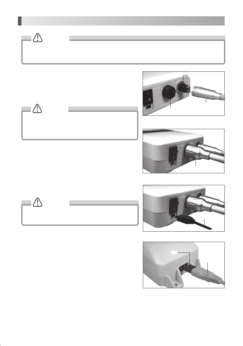
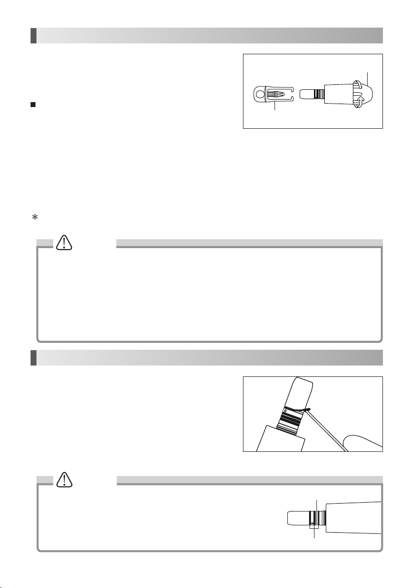
· Do not connect or disconnect the cord until the drive motor has completely stopped.
· Do not connect / disconnect the handpiece during operation.
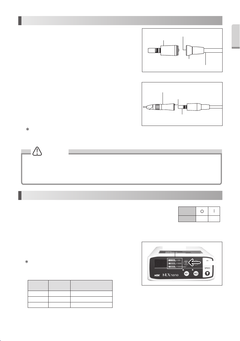
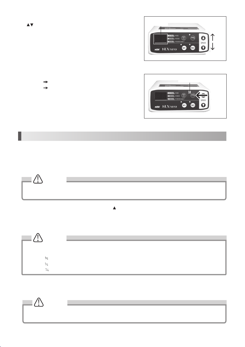
· Verify that the Speed Control Switch is adjusted within the allowable speed before use.
· Connect only 4-hole, 5-hole or 6-pin tubing.
· Air Requirements: dry, free from contamination and oil. Use a compressor with a dry air system. Install an air filter if
necessary. Blow out the lines before installation.
· Do not Autoclave (or any other high temperature Sterilization) Control Box, AC Adapter, Motor Cord.
· The user shall be responsible for operation, maintenance and operation.
· The operator is responsible for correct operational control, maintenance and inspection.
· Surface temperature shall be more than 60 ºC without using a coolant air, to avoid this event, be sure to use coolant air.
1. Specification
Model NLX nanoU (NE278)
Rated input AC28V 50/60 Hz
Drive Air Pressure 0.4MPa (4.0kgf/cm2)
Dimensions W127 x D149 x H54 mm
Control Box
Mode l NLX nano
Rotation Speed 2,000 - 40,000 min-1
Dimensions DØ22 x H70 mm
Motor
Model AC Adaptor(NE180)
Rated input AC120V 50/60Hz 41VA
AC230V 50/60Hz 41VA
Output AC28V 1.3A
Fuse
AC120V TR5-T C1 250V
19372 T1.6A
AC230V TR5-T C1 250V
800mA
Dimensions W100 x D178 x H64 mm
AC Adaptor
Water Supply More than 65 mL/min (0.2MPa)
Chip Air More than 1.5 L/min (0.2MPa)
Coolant Air Supply More than 6.5 NL/min (0.2MPa)

English
3
10
11
12
13
14
15
16
17
18
AC Adapter Connector
Motor Cord Connector
Turbine Hose Connector
Motor
Protection Plug
Motor Cap
Motor Cord (Unshielded 2.2m)
AC Cord (Unshielded 2.0m)
AC Adaptor (Unshielded cord 5.0m)
2. Component Names
Control Box
Indicator
Gear Ratio Lamp
Gear Ratio Select Key
FWD/REV Select Key
Rotation Speed Adjustment Key
M1 Key
M2 Key
Power Switch
1
2
3
4
5
6
7
8
9
13
14 15
16
17 18
1
23
456
78

4
Fig.1
Fig.2
Fig.3
Fig.4
CAUTION
CAUTION
CAUTION
Motor Cord Plug
Inlet
AC Cord
AC Adaptor Plug
3. Operating Control Box
· Do not use it other than the hose which we appointed.
· Do not use wet or contaminated air.
· Install an air filter if necessary. Blow out the lines before
installation.
3-1 Connect the handpiece tubing from the delivery unit you are
using
Fit the Turbine Hose Plug of the delivery unit to the Turbine Hose
Connector piping and tighten completely. (Fig. 1)
3-2 Connecting the Motor
Connect the motor by aligning the Motor Cord Plug and insert
firmly. Tighten it completely. (Fig. 2)
3-3 Connecting the AC adapter
Insert the AC adapter plug into the AC adapter connector before
pugging into wall outlet. (Fig. 3)
Never use the AC Adapter for other than the Control Box of this
product.
3-4 Connecting the Power Cord
Insert the Power Cord into the Inlet of AC Adapter. (Fig. 4)
· Be sure that there is no air or water coming from Turbine Hose when connecting to control box.
· Hand tighten the Nut properly without unnatural force, when you plug into Turbine Hose Connector and Motor Cord
Connector.
Turbine Hose Plug
Turbine Hose Connector
Motor Cord Connector

English
5
CAUTION
· Care should be taken when using any handpiece attachment which requires lubrication (E Type Micromotor).
Following lubrication stand the handpiece attachment vertically until the excess solution drains. Wipe the
handpiece then attach it to the Micromotor.
· Do not connect or disconnect the handpiece until the motor has completely stopped.
Fig.6
Fig.7
Motor Insert
Handpiece (Option)
Positioning Pin
4-2
Connectioning / disconnecting the motor and the handpiece
To insert the E-type handpiece in the Motor Insert, align handpiece
and motor, then turn those until its click. (Positioning pins are
aligned)
To remove the handpiece, simply pull out the handpiece from the
motor.
Handpiece (not included in NLX nano set.)
5. Operation Section
5-1 Insert the Power Cord Plug in AC outlet and turn the Power Switch on. When you turn on the
Power Switch, lamps and Indicator will come on.
5-2 Before using this system, make sure to do the Foot Air Calibration function.
(See 6-1 Foot Air Calibration)
Power Switch
Symbol Mark
Function OFF ON
5-3 Push the Gear Ratio Select Key to indicate the speed of the
attachment you will use. (Fig. 7)
Fig.5
Motor
Motor Cord
Motor Cord Nut
Motor Cord Connector
4. Handling the Motor
4-1 Connecting / disconnecting the motor and the motor cord
Align and insert firmly the Motor Pin into the pin holes of the Motor
Cord Connector, and fasten the Motor Cord Nut securely. (Fig. 5)
To remove the Motor Cord from the Motor, unscrew and detach the
motor cord nut, and gently pull out the motor cord connector.
Gear Ratio Lamp
PUSH
During Speed Setting, Indicator display "Speed".
For detail display, check table below.
Handpiece
Gear Ratio Indicator Speed (min-1(rpm))
16:1 1 - 25 100 - 2,500
1:1 2 - 40 2,000 - 40,000
1:5 1 - 20 10,000 - 200,000
Speed Display Table

6
NOTICE
NOTICE
Do this adjustment function after your purchase. Once it is adjusted, it will be memorized, and there is no need to
do this everytime.
· The displayed air pressure is only a guideline. Measure the correct air pressure with the air gauge.
· The unit of displayed air pressure is "kgf/cm2". For other unit, refer the bellow.
ex)0.1 0.01MPa
1.0 0.1MPa
3.0 0.3MPa.
NOTICE
· Default value is set to "0.5" .
· When the air pressure is not between "0.3" - "1.0", it is displayed "Eb", and will not be memorized
1)Press M2 key and Rotation Speed Adjustment Key( ) at the same time for more than 3 seconds.
2)With alarm sound, Indicator will change to "C1" (Lower air pressure limit setting mode).
3)By pressing the FWD/REV Rotation key, Speed Indicator shows " 0.0" and "Eb" mutually.
4)By stepping the Foot Pedal of the delivery unit, Indicator shows the present air pressure.
Fig.9
6. Convenient Functions
5-5 Select FWD/REV rotation using the FWD/REV Select Key. (Fig. 9)
Lamp ON REV
Lamp OFF FWD
5-6 The micromotor operation will be controlled by the air switch/Foot
Pedal of the delivery unit.
6-1 Foot Air Calibration
(Unit of Display = kgf/cm2)
By using this function, it enables you to use the maximum speed, 40,000 min-1(rpm), even though the air pressure of the
delivery system is not high enough, by setting upper and lower limit of the air pressure.
5)Control the Foot Pedal of the delivery unit, and maintain the air pressure between "0.3 " - "1.0". Press M2 key for
more than 3 seconds to memorize the lower limit of the air pressure.
Fig.8
5-4 Set the maximum speed using the Rotation Speed Adjustment Key
( ) . (Fig. 8)
Decrease
Increase
Indicator
FWD/REV Lamp
PUSH

English
7
NOTICE
The displayed air pressure is only a guideline. Measure the correct air pressure with the air meter.
NOTICE
· Default value is set to "3.0".
· When the air pressure is not between "2.0" - "4.0", it is displayed "Ec", and will not be memorized.
NOTICE
· Default value is set to " 3.5".
· Adjustable between "1.6" - "3.6".
9)Control the Foot Pedal of the delivery system, and maintain the air pressure between "2.0" - "4.0". Press M2 key until
it beep (more than 3 seconds) to memorize the upper limit of the air pressure.
10)Press both M2 key and Speed Adjustment Key( ) at the same time until it beep (more than 3 seconds), once again.
When it alarmed, this setting has completed. By setting Indicator by pressing Rotation Speed Key to " 40", and
now it is ready to use at the maximum speed, 40,000 min-1(rpm).
6-2 Light Brightness Adjusting Function
(Unit of Display = V)
Brightness of the Fiber Optic can be adjusted from this function.
1)Press M2 Key and Speed Adjustment Key( ) at the same time until it beep (more than 3 seconds).
2)With alarm sound, Indicator will change to " C1". Pressing the Gear Ratio Select key can change the Indicator and Gear
Ratio Lamp (C1 C2 C3 C1….)Set indicator in C3 (Light Brightness adjustment mode).Press FWD/REV Rotation
Key to proceed.
3)When Indicator changed to " 3.5"(Default value), press Speed Adjustment Key( ) and adjust the brightness.
4)Press M2 key until it beep (more than 3 seconds) to set the brightness.
5)Press M2 key and Speed Adjustment Key( ) at the same time for more than 3 seconds, once again. When it alarmed,
this setting has completed.
6-3 Program Function
It is possible to memorize settings (Speed, Gear Ratio, Forward/Reverse Direction)
After the setting, you can use your settings by pressing M1, M2 Key.
1)Set the values for Speed, Gear Ratio, Forward/Reverse Direction.
2)Press M1 Key or M2 Key until it beep (more than 3 seconds). When it alarmed, this setting has completed.
6)After setting lower limit, press Gear Ratio Select Key. Indicator will change to "C2 " (Upper air pressure limit
setting mode).
7) By pressing the FWD/REV Rotaion Key, Indicator shows " 0.0" and "Ec" mutually.
8)By stepping the Foot Pedal of the delivery system, Indicator shows the current air pressure.

8
CAUTION
· Do not Autoclave (or any other high temperature Sterilization) Control Box, AC Adapter, Motor Cord.
· Do not lubricate the motor.
· Do not wipe nor immerse the system in acidic water or acidic solutions.
· Do not sterilize with dirt on the surface. It might cause rust.
· Do not use Protection Plug without the mounting O-Ring. It may cause a malfunction. If O-Ring had damaged,
replace it immediately.
O-Ring (Protection Plug ): Order code 0312457102
· You can hang Protection Plug on the anywhere to prevent loosing it.
· Do not hung the Protection Plug with motor. It may drop the motor and cause damage.
CAUTION
There are 4 O-Rings on the Motor Insert. Blue one is thinner than other 3 pieces.
Make sure to order it.
Fig.10
Fig.11
Tighten
ex.)Autoclave for 20 min. at 121°C, or 15 min. at 132°C.
7)Keep the Motor in the autoclave pouch to keep it clean until you use it.
Sterilization at 121°C for more than 15 minutes is recommended by EN13060 or EN ISO17665-1.
8. Maintenance
If the O-Ring became depleted, such as difficult to connect the
handpiece or air or water might leak, replace the O-Ring.
7. Sterilization
Sterilize the motor only.
For the sterilization method, we recommend the autoclave sterilization
method.
Sterilization is required first time you use and after each patient as noted
below.
Autoclaving
1)Turn off the Power.
2)Detach the motor from the Motor Cord. (Refer to 4-1 Connecting /
disconnecting the Motor and the Motor Cord)
3)Clean the surface of the motor with brush etc. (Do not use the
metal brush), and wipe it with the cotton moistened with
disinfecting alcohol.
4)Screw the Motor Cap to the Motor. Put the Protection Plug to the motor insert. (Fig. 10)
5)Insert into an autoclave pouch. Seal the pouch.
6)Autoclavable up to max. 135°C.
(1) Changing the Oring
Remove the O-Ring at the Motor Insert with a pointed tool, and
mount the new O-Rings into the groove.
Protection Plug
Motor Cap
O-Ring (Black)
O-Ring (Blue)

English
9
9. Error Code
Error
Code Trouble Cause Check/Remedy
E0 Overcurrent error.
(In circuit)
Detected overcurrent in the circuit. Contact your dealer.
E1 Overcurrent error.
(In software)
Detected overcurrent in the software. Contact your dealer.
E2 Retry Error Motor stopped by the overload, and not
able to restart.
Contact your dealer.
E3 ITRIP Error Faulty Motor or Internal circuit. Contact your dealer.
E5 Overvoltage Input Error Overvoltage is given to the Control Box. Contact your dealer.
E6 LED voltage Error Overvoltage is given (more than 3.7V)
from the Internal circuit.
Contact your dealer.
E8 Overheat Error High temperature safe system is
functioning, due to long-time use at a high
load.
Cool it down for a while, and try again.
E9 Motor Start Error - Motor didn't reach the preset speed in a
prescribed period of time.
- Break down of a motor cord wire, or
internal circuit malfunction.
Contact your dealer.
EA LED voltage Error Voltage for the LED didin't reach the
preset speed in a prescribed period of
time.
Contact your dealer.
Eb Air Offset Error Lower than preset " Lower limit of the air
pressure"
Displayed by Foot Air Calibration function.
Not a malfunction.
Ec Air Full Scale Error - Higher than preset "Upper limit of the air
pressure".
- Air pressure higher than 0.4MPa (4.0kgf/
cm2) is given.
Displayed by Foot Air Calibration function.
Not a malfunction.
EE EEPROM Error Malfunction of the memory for the setting
values.
Contact your dealer.
If the motor stops due to an abnormality such as a malfunction, overload, break or incorrect usage, it automatically checks
the state of the Control Box and detects the cause of the abnormality and displays an error code on the Indicator. If an error
code is displayed, turn on the power again and check whether the same error code is displayed. If the same error code is
displayed, take action by referring to the instructions provided in the "Check/Remedy" column in the following table.
CAUTION
It might happen if the O-Ring becomes depleted.
· Air/Water leak
· Air/Water does not came off
· Vibration
· Difficult to connect/disconnect the handpiece

10
10. Troubleshooting
When trouble is found, check the following again before consulting NSK dealer. If none of these is applicable or the the trouble
is not remedied even after action has been taken, a failure of this product is suspected.
Check/Remedy Cause Solution
Pilot Lamp does not light. Power Switch is OFF. Turn ON the switch.
AC Adapter is not connected correctly. Check the connection.
Internal Fuse is blown, due to some reason. Contact your dealer.
Motor does not run Tubing, Motor Cord, AC Adapter is not connected
correctly.
Check the connection.
Air pressure is not given, or not proper from the
delivery unit.
Check the air pressure of the delivery
system.
Check the ERROR CODE in the Indicator. Refer to 9. ERROR CODE.
The rotation speed does not
rise.
Air pressure is not given, or not proper from the
delivery unit.
Check the air pressure of the delivery
system.
Air pressure of the delivery unit is lower than the
“Lower limit of the air pressure”.
Do "6-1 Foot Air Calibration".
It beeps when turn on the
switch.
You are stepping on the Foot Pedal when turning on
the power switch. (Safety function)
Do not step the Foot Pedal, and turn on the
power switch.
LED does not light. Reached the end of life expectancy. Contact your dealer.
Motor heats up abnormally
during rotation.
Coolant air is not given, or not proper from the
delivery unit.
Check the air pressure of the delivery
system.
Water leakage Tubing, Motor Cord is not connected correctly. Contact your dealer.
If it is from Control Box, something is wrong within
the Control Box.
Check the connection.
When turned on, the setting
values are different from
what used to be when
turned off.
Turned off the motor while rotating. Turn off after the Motor has stopped.
11. Warranty
Manufacturer warrants its products to the original purchaser against defects in material and workmanship under normal
practices of installation, use and servicing. are expendable components, and are not covered by this warranty. In case the
product fails within 30 days from the date of installation, immediately report with the proof of your purchase to the dealer you
purchased from.
12. Disposing Product
Consult with dealer from whom you purchased it about waster despoil.

English
11
Guidance and manufacturer's declaration - electromagnetic emissions
The NLX nano is intended for use in the electromagnetic environment specified below.The customer or the user of the NLX nano and manual should assure that is
used in such an environment.
Emissions test Emissions test Electromagnetic environment - guidance
RF emissions CISPR11 Group 1 The NLX nano uses RF energy only for its internal function. Therefore, its RF emissions are very low and are
not likely to cause any interference in nearby electronic equipment.
RF emmissions CISPR11 class B The NLX nano is suitable for use in all establishments, including domestic estabilishments and those directly
connected to the public low-voltage power supply network that supplynetwork that spplies buidings used for
domestic purposes.
(*)This applies to the AC230V system. For AC120V system, this is “Not applicable”.
Harmonic emissions
IEC61000-3-2
class A
Voltage fluctuations/flicker
emissions IEC61000-3-3
Complies
Guidance and manufacturer's declaration - electromagnetic immunity
The NLX nano is intended for use in the electromagnetic environment specified below.The customer or the user of the NLX nano and manual should assure that it is
used in such an environment.
Immunity test IEC60601 test level Compliance level Electromagnetic environment - guidance
Electrostatic discharge (ESD)
IEC61000-4-2
±6kV contact
±8kV air
±6kV contact
±8kV air
Floors should be wood, concrete or ceramic tile. If floors are covered
with synthetic material, the relative humidity should be at least 30%.
Electrical fast transient/burst
IEC61000-4-4
±2kV for power supply
lines
±1kV for input/output
±2kV for power supply lines
No input/output line
Mains power quality should be that of a typical commercial or hospital
environment.
Surge IEC61000-4-5 ±1kV line(s) to line(s)
±2kV line(s) to earth
±1kV line to line
±2kV lines to earth
Mains power quality should be that of a typical commercial or hospital
environment.
Voltage dips, short
interruptions and voltage
variations on power supply
input lines IEC61000-4-11
<5% Ut
(>95% dip in Ut) for 0.5
cycle 40% Ut
<5% Ut
(>95% dip in Ut) for 0.5 cycle
40% Ut
(60% dip in Ut) for 5 cycles
70% Ut
(30% dip in Ut) for 25 cycles
<5% Ut
(>95% dip in Ut) for 5 sec
Mains power quality should be that of a typical commercial or hospital
environment. If the user of the NLX nano requires continued operation
during power mains interruptions, it is recommended that the NLX nano
be powered from an uninterruptible power supply or a battery.
Power frequency (50/60Hz)
magnetic field IEC61000-4-8
3 A/m 3 A/m Power frequency magnetic fields should be at levels characteristic of a
typical location in a typical commercial or hospital environment.
NOTE: Ut is the a.c. mains voltage prior to application of the test level.
Symbols
TUV Rhineland of North America is a Nationally Recognized Testing Laboratory (NRTL) in the United States and is accredited by
the Standards Council of Canada to certify electro-medical products with Canadian National Standards.
Follow the waste of electric and electronic equipment (WEEE) Directive (2002/96/EC) to dispose of the product and
accessories.
Consult operation instructions. Manufacturer.
This conforms to CE European Directive of “Medical equipment directive 93/42/EEC.”
Type B applied part. Autoclavable up to Max.135°C. *for detail see Sterilization.
Marking on the outside of Equipment or Equipment parts that include RF transmitters or that apply RF electromagnetic energy
for diagnosis or treatment.
Class II Equipment.

12
Recommended separation distances between portable and mobile RF communications equipment and the NLX nano
The NLX nano is intended for use in an electromagnetic environment in which radiated RF disturbances are controlled. The customer or the user of the NLX nano can
help prevent electromagnetic interference by maintaining a minimum distance between portable and mobile RF communications equipment (transmitters) and the
as recommended below, according to the maximum output power of the communications equipment.
Rated maximum output power of transmitter
W
Separation distance according to frequency of transmitter
150kHz to 80MHz 80MHz to 800MHz 800MHz to 2.5GHz
0.01 0.12 0.12 0.23
0.1 0.38 0.38 0.73
1 1.2 1.2 2.3
10 3.8 3.8 7.3
100 12 12 23
For transmitters rated at a maximum output power not listed above, the recommended separation distance d in meters (m) can be estimated using the equation
applicable to the frequency of the transmitter, where P is the maximum output power rating of the transmitter in watts (W) according to the transmitter manufacturer.
NOTE 1 At 80 MHz and 800 MHz, the separation distance for the higher frequency range applies.
NOTE 2 These guidelines may not apply in all situations. Electromagnetic propagation is affected by absorption and reflection from structures, objects and people.
Guidance and manufacturer's declaration - electromagnetic immunity
The NLX nano is intended for use in the electromagnetic environment specified below.The customer or the user of the NLX nano and manual should assure that it is
used in such an environment.
Immunity test IEC60601 test level Compliance level Electromagnetic environment - guidance
Conducted RF
IEC61000-4-6
Radiated RF
IEC61000-4-3
3Vrms
150 kHz to 80MHz
3V/m
80MHz to 2.5 GHz
3Vrms
3V/m
Portable and mobile RF communications equipment should be used no closer to any
part of the NLX nano, including cables, than the recommended separation distance
calculated from the equation applicable to the frequency of the transmitter.
Recommended separation distance
d = 1.2 P
d = 1.2 P 80MHz to 800MHz
d = 2.3 P 800MHz to 2.5GHz
Where P is the maximum output power rating of the transmitter in watts
(W)according to the transmitter manufacturer and d is the recommended
separationdistance in meters (m).
Field strengths from fixed RF transmitters as determined by an electromagnetic
site surveya, should be less than the compliance level in each frequency rangeb,
Interference may occur in the vicinity of equipment marked with the following
symbol:
NOTE 1 At 80MHz and 800MHz, the higher frequency range applies.
NOTE 2 These guidelines may not apply in all situations. Electromagnetic propagation is affected by absorption and reflection from structures, objects and people.
a
Field strengths from fixed transmitters, such as base stations for radio (cellular/cordless) telephones and land mobiles radios, amateur radio, AM and FM
radio broadcast and TV broadcast cannot be predicted theoretically with accuracy.To assess the electromagnetic environment due to fixed RF transmitters, an
electromagnetic site survey should be considered. If the measured field strength in the location in which the NLX nano is used exceeds the applicable RF compliance
level above, the NLX nano should be observed to verity normal operation. If abnormal performance is observed, additional measures may be necessary, such as
reorienting or relocating the NLX nano.
b Over the frequency range 150kHz to 80MHz, field strengths should be less than 3 V/m.

13
Français
Manuel d’utilisation
Classification de l’équipement
Type de protection contre les chocs électriques:
- Equipement de classe II :
Degré de protection contre les chocs électriques:
- Pièce appliquée type B :
Méthode de stérilisation ou désinfection recommandée par le fabricant:
- Cf. 7. STERILISATION
Niveau de sécurité de l’appareil en présence de mélanges anesthésiants inflammables avec de l’air, de l’oxygène ou de l’
oxyde d’azote :
L’APPAREIL ne peut pas être utilisé en présence de mélanges anesthésiants inflammables avec de l’air, de l’oxygène ou de l’
oxyde d’azote.
Utilisation:
- Fonctionnement continu
· POUR EVITER LES CHOCS ELECTRIQUES, ne débranchez pas le cordon d'alimentation avec les mains humides.
· POUR EVITER LES CHOCS ELECTRIQUES, veillez à ne pas mouiller le boîtier de contrôle.
· POUR EVITER LES CHOCS ELECTRIQUES, ne débranchez pas le cordon d'alimentation brutalement.
· POUR EVITER LES CHOCS ELECTRIQUES, utilisez une prise électrique reliées à la terre.
· Si vous constatez une anomalie, comme des vibrations, une production de chaleur, un bruit anormal, etc., avant ou
pendant l'utilisation du boîtier de contrôle, arrêtez de l'utiliser immédiatement.
· Utilisez un fusible de la puissance spécifiée. (CA120V: T1.6A 250V (Réf. FU100, FU101), CA230V: T800mA 250V (Réf.
FU100, FU101)
ATTENTION
Classification Niveau et gravité du danger ou des dommages
ATTENTION Fournit une instruction s’il existe un risque de dommage physique ou de blessure personneller.
AVERTISSEMENT
Fournit une instruction s’il existe un risque de dommage physique ou de blessure personnelle
mineure à moyenne.
REMARQUE Fournit une instruction à respecter pour des raisons de sécurité.
Lisez bien ces instructions de sécurité avant d’utiliser l’appareil et utilisez le produit conformément à celles-ci.
Ces instructions vous indiqueront comment utiliser le produit en toute sécurité et éviter de mettre vos patients ou vous-
même en danger. Le classement est dressé en fonction du niveau et/ou de la gravité du danger. Tous les informations liées
à la sécurité doivent être respectées.
Précautions d’emploi et d’utilisation
AVERTISSEMENT
· Lorsque vous utilisez ce système, veillez toujours à la sécurité du patient.
· L’appareil est uniquement conçu pour un usage dentaire clinique par du personnel qualifié.
· Chaque connexion doit être fermement connectée. Si elle n'est pas fermement connectée, cela peut entrainer une fuite
d'air/d'eau ou un dysfonctionnement de la LED.
· Veillez à ce que l’appareil ne soit soumis à aucun choc. Ne le jetez pas. Ceci pourrait engendrer un dysfonctionnement.
· Ce système peut être utilisé avec une connexion de type B ou C ISO 9168.
· L’appareil fonctionne normalement dans un environnement dont la température est comprise entre 0 et 40°C, dont le
taux d'humidité est compris entre 10 et 85% RH, dont la pression atmosphérique est comprise entre 700 et 1060hPa
et s’il n’y a pas de condensation dans le boîtier de contrôle. Son utilisation en dehors de ces limites peut entraîner un
dysfonctionnement.
· Lorsque vous installez le boîtier de contrôle ou le moteur, ne courbez et ne tordez PAS le tube ou le cordon. Aucune force
particulière n'est nécessaire pour réaliser l'installation.
· N'utilisez pas d'air contaminé (par de la poussière ou de l'humidité). Si l'air contient de l'eau ou des poussières, il pourrait
entraîner un dysfonctionnement ou une surchauffe.
· Ne connectez pas le micromoteur NLX nano au Ti-Max NL400. Cela pourrait endommager la LED.

14
AVERTISSEMENT
· Pendant la rotation, le moteur et le cordon moteur peuvent affecter l'ordinateur et le câble LAN. Il se peut qu’un bruit soit
perçu en cas d’utilisation près d’un récepteur radio.
· Après le traitement, éteignez immédiatement l'appareil et stoppez l'arrivée d'air. Enlevez le cordon d'alimentation si le
boîtier de contrôle n’est pas utilisé pendant une période prolongée.
· L'utilisateur est responsable de l'utilisation et de l'entretien des appareils médicaux.
· Conservez le système dans un endroit dont la température est comprise entre -10 et 60°C, dont le taux d'humidité se
situe entre 10 et 85%RH et d'une pression atmosphérique située entre 500 et 1060 hPa. Le système ne doit pas être
soumis à l'air contenant des poussières, du soufre ou de l'air salin
REMARQUE
Boîtier de contrôle
· Saisissez le cordon par la prise pour l'enlever de la prise. Ne tirez et n'arrachez PAS la prise par le cordon. Vous pourriez
causer un arrachement du câble ou un dysfonctionnement.
· Veillez à ne pas placer le cordon d’alimentation électrique près d'un brûleur à gaz. N'essayez jamais de réparer un
cordon moteur brûlé. Remplacez-le toujours par un nouveau cordon.
· Avant toute utilisation, vérifiez toujours l'éventuelle présence de vibrations, de bruit et de surchauffe. En cas d'anomalie,
arrêtez immédiatement d'utiliser l'appareil et contactez un revendeur NSK agréé.
· Veillez à ne pas éclabousser le boîtier de contrôle car cela pourrait entraîner un incendie ou un choc électrique dû à un
court-circuit.
Moteur, Pièce à main(Option)
· N'utilisez pas ce système sous une forte pression pendant une période prolongée. Cela pourrait entraîner une surchauffe.
· Ne connectez/déconnectez pas le cordon avant que le moteur soit complètement arrêté.
· Ne connectez/déconnectez pas la pièce à main pendant l'utilisation.
· Veillez à ce que le bouton de réglage de la vitesse soit positionné sur la vitesse autorisée avant d'utiliser l'appareil.
· Ne connectez que des tubes 4 trous, 5 trous ou 6 broches.
· Recommandations liées à l'air : l'air doit être sec, non contaminé et sans huile. Utilisez un compresseur avec système
pour air sec. Installez un filtre à air si nécessaire. Soufflez dans les lignes avant l'installation.
· Ne stérilisez pas par autoclave (ou via tout autre type de stérilisation haute température) le boîtier de contrôle, le
transformateur électrique CA et le cordon moteur.
· L'utilisateur est responsable de l'utilisation, de l'entretien et de la manipulation.
· Les utilisateurs sont responsables des traitements, de l’entretien et de la vérification de l’appareil
· La température de la surface dépassera les 60°C sans utiliser d’air de refroidissement. Pour éviter ceci, veillez à utiliser
un air de refroidissement.
1. Spécifications
Modèle NLX nanoU (NE278)
Entrée estimée CA28V 50/60 Hz
Pression d’air 0,4MPa (4,0kgf/cm2)
Dimensions W127 x D149 x H54 mm
Boîtier de contrôle
Modèle Adaptateur CA(NE180)
Entrée estimée CA120V 50/60Hz 41VA
CA230V 50/60Hz 41VA
Sortie CA28V 1,3A
Fusible
CA120VTR5-T C1 250V
19372 T1, 6A
CA230VTR5-T C1 250V
800mA
Dimensions W100 x D178 x H64 mm
Transformateur électrique CA
Modèle NLX nano
Vitesse de rotation 2.000 - 40.000 min-1
Dimensions DØ22 x H70 mm
Moteur
Pression hydraulique Plus de 65 mL/min (0.2MPa)
Pneumatique Plus de 1.5 L/min (0.2MPa)
Consommation d’air de refroidissement Plus de 6.5 NL/min (0.2MPa)

15
Français
10
11
12
13
14
15
16
17
18
Connecteur du transformateur électrique CA
Connecteur cordon moteur
Connecteur du tuyau de turbine
Moteur
Prise de Protection
Couvercle moteur
Cordon moteur (Uns ielded 2.2m)
Cordon du transformateur électrique CA (Unsielded 2.0m)
Alimentation électrique CA (Unsielded Cordon 5.0m)
2. Nom des composants
Boîtier de contrôle
Indicateur de vitesse
Indicateur rapport de vitesse
Bouton de sélection du rapport de vitesse
Bouton Avant/Arrière
Bouton de réglage de la vitesse de rotation
Bouton M1
Bouton M2
Interrupteur
1
2
3
4
5
6
7
8
9
13
14 15
16
17 18
1
23
456
78

16
Fig.1
Fig.2
Fig.3
Fig.4
AVERTISSEMENT
AVERTISSEMENT
AVERTISSEMENT
Prise cordon moteur
Prise
Cordon
3. Utilisation du boîtier de contrôle
· N'utilisez pas d'autre tuyau que celui indiqué.
· N'utilisez pas d'air humide ou contaminé.
· Installez un filtre à air si nécessaire. Envoyez de l’air dans les
lignes avant l'installation.
3-1 Branchez le cordon de la pièce à main depuis le boitier d’
alimentation que vous utilisez
Placez la prise du tuyau de turbine de le boitier d’alimenation au
niveau du connecteur de tuyau de turbine et serrez à fond. (Fig. 1)
3-2 Connexion du moteur
Connectez le moteur en alignant la prise du cordon moteur et
insérez-la fermement. Serrez à fond. (Fig. 2)
3-3 Connexion du transformateur électrique CA
Insérez la prise du transformateur électrique CA dans le connecteur
du transformateur électrique CA avant de le brancher dans la prise
murale. (Fig. 3)
N'utilisez jamais le transformateur CA pour un autre appareil
que le boîtier de contrôle de ce produit.
3-4 Connexion du cordon d'alimentation
Insérez le cordon d'alimentation dans la prise du transformateur
CA. (Fig. 4)
· Veillez à ce qu'il n'y ait pas d'air ou d'eau provenant du tuyau de turbine lorsque vous le connectez au boîtier de
contrôle.
· Votre main doit serrer l'écrou correctement et sans exercer de force importante lorsque vous effectuez le
branchement du cordon de turbine et du cordon moteur.
Prise de tuyau de turbine
Connecteur du
tuyau de turbine
Connecteur du cordon moteur
Prise du transformateur
électrique CA

17
Français
AVERTISSEMENT
Soyez vigilant lorsque vous utilisez une pièce à main qui doit être lubrifiée (micromoteur de type E). Après la
lubrification, placez la pièce à main en position verticale jusqu'à ce que l’excédent d’huile ait séché. Essuyez la
pièce à main et connectez-la ensuite au micromoteur.
Fig.6
Fig.7
Insert moteur
Pièce à main (Option)
Broche de positionnement
4-2
Connecter/Déconnecter le moteur et la pièce à main
Pour insérer la pièce à main de type E dans l'insert moteur, alignez
la pièce à main et le moteur et tournez-les jusqu'à ce que vous
entendiez un clic. (les broches de positionnement sont alignées)
Pour enlever la pièce à main, il vous suffit de retirer la pièce à main
du moteur.
Pièce à main (Non inclus dans le set NLX nano)
5. Section d'utilisation
5-1 Insérez la prise du cordon d'alimentation dans la prise d’alimentation CA et positionnez le
bouton sur ON (marche). Lorsque vous allumez l'appareil, les indicateurs lumineux et
l'indicateur de vitesse s'allumeront.
5-2 Avant d'utiliser cet appareil, veillez à faire fonctionner le calibrage de l'air au pied (Cf. 6-1 Calibrage de l'air au pied)
Marque
Marche/Arrêt
Fonction OFF ON
5-3 Appuyez sur le bouton de sélection du rapport de vitesse pour
indiquer la vitesse de l'instrument que vous allez utiliser. (Fig. 7)
Pièce à main Rapport
de vitesse Indicateur Vitesse (min-1(rpm))
16:1 1 - 25 100 - 2.500
1:1 2 - 40 2.000 - 40.000
1:5 1 - 20 10.000 - 200.000
Fig.5
Moteur
Cordon
Ecrou cordon moteur
Connecteur cordon
4. Utilisation du moteur
4-1 Connexion/Déconnexion du moteur et du cordon moteur
Alignez et insérez fermement la broche du moteur dans les trous
de broche du connecteur du cordon moteur et fixez correctement
l'écrou du cordon moteur. (Fig. 5)
Pour enlever le cordon moteur du moteur, dévissez et détachez
l'écrou du cordon moteur et retirez délicatement le connecteur du
cordon moteur.
Indicateur rapport de vitesse
APPU

18
REMARQUE
· La valeur par défaut est de "0,5" (kgf/cm2).
· Lorsque la pression d'air n'est pas comprise entre "0,3" et "1,0", "Eb" est affiché et ce ne sera pas mémorisé.
REMARQUE
Définissez ce réglage après votre achat. Une fois paramétré, il sera mémorisé et vous ne devrez plus le redéfinir à
chaque fois.
REMARQUE
· La pression d'air affichée est uniquement indicative. Mesurez la bonne pression d'air à l'aide de la jauge d'air.
· Le boîtier de contrôle de la pression d'air affichée correspond à "kgf/cm2". Pour une autre unité, cf. ci-dessous.
ex)0,1kgf/cm2= 0,01MPa
1,0kgf/cm2= 0,1MPa
3,0kgf/cm2= 0,3MPa
Fig.9
1)Appuyez sur le bouton M2 et le bouton de réglage de la vitesse de rotation ( ) en même temps pendant plus de 3
secondes.
2)Vous entendrez un signal sonore, l'indicateur de vitesse passera à "C1" (Mode de réglage de la limite inférieure de la
pression de l'air).
3)En appuyant sur le bouton de rotation AVANT/ARRIERE, l'indicateur de vitesse indiquera "0.0" et "Eb" mutuellement.
4)Si vous appuyez sur la pédale du boitier d’alimentation, l'indicateur de vitesse indiquera la pression d'air actuelle. (l'unité
est le kgf/cm2)
6. Fonctions pratiques
5-5 Sélectionnez la rotation AVANT/ARRIERE à l'aide du bouton de
sélection AVANT/ARRIERE. (Fig. 9)
Indicateur lumineux ALLUME ARR
Indicateur lumineux ETEINT AVANT
5-6 Le fonctionnement du micromoteur sera contrôlé par la pédale/
bouton d'air du boitier d’alimentation.
6-1 Calibrage de l'air au pied
Cette fonction vous permet d'utiliser la vitesse maximale de 40.000 min-1(rpm), même si la pression de l'air du système d’
alimentation n'est pas assez élevée en définissant les limites inférieure et supérieure de la pression de l'air.
5)Contrôler la pédale du boitier d’alimentation et maintenir la pression d'air entre "0,3 " et "1,0". Appuyez sur le bouton
M2 pendant plus de 3 secondes pour mémoriser la limite inférieure de la pression d'airsure.
Fig.8
5-4 Sélectionnez la vitesse maximale en utilisant le bouton de réglage de
la vitesse de rotation( ). (Fig. 8)
Baisse
Augmentation
Indicateur rapport de vitesse
Lampe AVANT/ARRIERE
APPU

19
Français
REMARQUE
· La pression d'air affichée est uniquement indicative. Mesurez la bonne pression d'air à l'aide de la jauge d'air.
· Le boîtier de contrôle de la pression d'air affichée correspond à "kgf/cm2". Pour les autres unités, référez-vous à
la REMARQUE du point 4 "kgf/cm2". For other unit, refer to the NOTICE described in 4).
REMARQUE
· La valeur par défaut est de "3,0" (kgf/cm2).
· Lorsque la pression d'air n'est pas comprise entre "2,0" et "4,0", "Ec" est affiché et ce ne sera pas mémorisé.
REMARQUE
· La valeur par défaut est de "3,5" (V).
· Ajustable entre "1,6" et "3,6".
9)Contrôler la pédale du système d’alimentation et maintenir la pression d'air entre "2,0" et "4,0". Appuyez sur le bouton
M2 jusqu'à ce que vous entendiez un bip (plus de 3 secondes) pour enregistrer la limite supérieure de la pression d'air.
10)Appuyez sur le bouton M2 et le bouton de réglage de la vitesse( ) en même temps jusqu'à ce que vous entendiez un
bip (plus de 3 secondes) encore une fois. Lorsque vous entendez le signal d'alarme, le paramétrage est terminé.
Paramétrez l'indicateur de vitesse en plaçant le bouton de vitesse de rotation sur "40" et vous pourrez utiliser l'appareil
à la vitesse maximale, 40,000 min-1(rpm).
6-2 Fonction de réglage de la luminosité
La luminosité de la fibre optique peut être réglée grâce à cette fonction.
1)Appuyez sur le bouton M2 et le bouton de réglage de la vitessey ( ) en même temps jusqu'à ce que vous entendiez un
bip (plus de 3 secondes).
2)Lorsque vous entendrez le signal sonore, l'indicateur de vitesse passera à "C1". En appuyant sur le bouton de sélection
du rapport de vitesse, vous pouvez modifier l'indicateur de vitesse et l’indicateur lumineux de rapport de vitesse (C1
C2 C3 C1….)Placez l'indicateur sur C3 (Mode de réglage de la luminosité). Appuyez sur le bouton de rotation
AVANT/ARRIERE pour procéder.
3) Lorsque l'indicateur de vitesse est passé à "3,5"(valeur par défaut), appuyez sur le bouton de réglage de la vitesse ( )
et ajustez la luminosité
4)Appuyez sur le bouton M2 jusqu'à ce que vous entendiez un bip (plus de 3 secondes) pour régler la luminosité.
5)Appuyez sur le bouton M2 et sur le bouton de réglage de la vitesse( ) en même temps et pendant plus de 3 secondes
encore une fois. Lorsque vous entendez le signal sonore, le paramétrage est terminé.
6-3 Fonction du programme
Vous pouvez enregistrer les paramétrages (vitesse, rapport de vitesse, direction avant/arrière). Après le paramétrage, vous
pouvez utiliser vos réglages en appuyant sur le bouton M1 ou M2.
1)Définir les valeurs pour la vitesse, le rapport de vitesse, la direction avant/arrière.
2)Appuyez sur le bouton M1 ou M2 jusqu'à ce que vous entendiez un bip (plus de 3 secondes). Lorsque vous entendez le
signal sonore, le paramétrage est terminé.
6)Après avoir défini la limite inférieure, appuyez sur le bouton de sélection du rapport de vitesse. L'indicateur de vitesse
passera à "C2 "(Mode de définition de la limite supérieure de la pression d'air setting mode).
7) En appuyant sur le bouton de rotation AVANT/ARRIERE, l'indicateur de vitesse affichera "0,0" et "Ec" mutuellement.
8)Si vous appuyez sur la pédale du boitier d’alimentation, l'indicateur de vitesse indiquera la pression d'air actuelle (l'unité
est lekgf/cm2)
Table of contents
Languages:
Other NSK Dental Equipment manuals

NSK
NSK Viva Ace User manual

NSK
NSK Prophy-Mate neo User manual

NSK
NSK Ti-Max X Series User manual

NSK
NSK Ti-Max NL400 CDE User manual

NSK
NSK Ti-Max S-Max Series User manual

NSK
NSK SGM-E256RTL User manual

NSK
NSK Ti-max Z45L User manual

NSK
NSK AS2000 M4 User manual

NSK
NSK Ti-max Z45L User manual

NSK
NSK MPA Series User manual