manuals.online logo
Brands
  1. Home
  2. •
  3. Brands
  4. •
  5. Stryker
  6. •
  7. Medical Equipment
  8. •
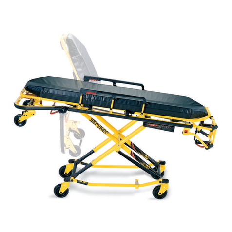
  9. Stryker Power-PRO IT Cot 6516 User manual

Stryker Power-PRO IT Cot 6516 User manual

PPoowweerr--PPRROO™™ IITT CCoott
MMaaiinntteennaannccee MMaannuuaall
6516
EN
6516-109-002 Rev AB.0 2022-01
TTaabbllee ooff CCoonntteennttss
Warning/Caution/Note Definition ..............................................................................................................................4
Summary of safety precautions ................................................................................................................................4
Pinch points .......................................................................................................................................................4
Introduction for service .............................................................................................................................................6
Expected service life ...............................................................................................................................................6
Contact information.................................................................................................................................................6
Serial number location - Power-PRO ........................................................................................................................6
Serial number location - SMRT ................................................................................................................................6
Preventive maintenance ...........................................................................................................................................7
Lubrication .............................................................................................................................................................7
Regular inspection and adjustments.........................................................................................................................7
Every three months or six hours...........................................................................................................................7
Every month or two hours ...................................................................................................................................8
Every six months or 12 hours ..............................................................................................................................8
Every 12 months or 24 hours...............................................................................................................................9
Maintenance record ................................................................................................................................................9
Training record .....................................................................................................................................................10
Troubleshooting ......................................................................................................................................................12
Electronics and hydraulics locator ..........................................................................................................................12
Hydraulic assembly...............................................................................................................................................13
Hydraulic assembly wiring schematics....................................................................................................................13
Electrical system block diagram - lift and extend (unload) functions...........................................................................14
Electrical system block diagram - lower and retract functions....................................................................................15
SMRT charger power LED is NOT illuminated .........................................................................................................15
SMRT charger will not charge the SMRT Pak..........................................................................................................16
SMRT charger indicator LEDs are NOT illuminated when the Pak is inserted.............................................................16
A fully charged SMRT Pak does not provide sufficient power for cot operation ...........................................................16
Charger indicates a temperature delay (flashing amber LED), but the Pak is within the normal operating temperature
range ...................................................................................................................................................................17
SMRT charger indicates a SMRT Pak error (amber LED), but the Pak performs well on the cot...................................17
Litter drifts (without patient weight) .........................................................................................................................17
Base drifts (without patient weight) .........................................................................................................................17
Litter does not lower in the powered mode ..............................................................................................................17
Litter does not extend in the powered mode ............................................................................................................18
Base does not retract in the powered mode.............................................................................................................18
Base does not extend in the manual mode..............................................................................................................18
Base does not retract in the manual mode ..............................................................................................................19
Litter does not retract in the manual mode (with patient weight) ................................................................................19
Litter does not extend in the manual mode ..............................................................................................................19
High speed retract does not engage .......................................................................................................................19
LCD error codes - main micro ................................................................................................................................19
Safety micro .........................................................................................................................................................20
Main cable assembly.............................................................................................................................................21
Main cable assembly wiring schematics..................................................................................................................21
Control board assembly.........................................................................................................................................22
Control board wiring schematics.............................................................................................................................23
Service ....................................................................................................................................................................24
Head section replacement .....................................................................................................................................24
Manual release cable adjustment ...........................................................................................................................24
Filling the hydraulics assembly reservoir.................................................................................................................25
Wheel locking force adjustment..............................................................................................................................26
Steer-Lock mechanism adjustment.........................................................................................................................26
Cot retaining post adjustment.................................................................................................................................27
Cot retaining post replacement...............................................................................................................................28
Cot retaining post screw replacement .....................................................................................................................28
6516-109-002 Rev AB.0 1 EN
Hydraulic A valve or B valve replacement ...............................................................................................................29
Hydraulic manual release valve replacement ..........................................................................................................30
Hydraulic cylinder replacement ..............................................................................................................................30
Hydraulic hose replacement...................................................................................................................................32
Terminal block replacement...................................................................................................................................33
12 VDC automotive cable fuse replacement............................................................................................................35
Cot assembly ..........................................................................................................................................................36
Base assembly .......................................................................................................................................................40
Caster horn assembly - 6082-002-012 ...................................................................................................................44
Adjustable caster lock assembly ............................................................................................................................45
6 in. molded wheel assembly - 6060-002-010........................................................................................................46
Load wheel, hard - 6500-101-086 ..........................................................................................................................47
Wheel, front - 6500-001-086...................................................................................................................................48
No Steer-Lock option - 6506-037-000 ....................................................................................................................49
Steer-Lock option - 6506-038-000..........................................................................................................................50
Steer-Lock sub assembly, head end ......................................................................................................................51
Outer lift tube assembly, base pivot - 6500-301-021..............................................................................................52
Inner lift tube assembly, base pivot - 6500-301-022 ..............................................................................................53
Inner lift tube, litter pivot, patient right assembly - 6500-001-034 ..........................................................................54
Inner lift tube, litter pivot, patient left assembly - 6500-001-035.............................................................................55
Outer rail sub assembly, right .................................................................................................................................56
Outer rail sub assembly, left ...................................................................................................................................57
Hall sensor assembly..............................................................................................................................................58
Sensor housing assembly ......................................................................................................................................59
Power plant assembly.............................................................................................................................................60
Hydraulic sub assembly - 6500-101-030................................................................................................................62
Foot end assembly .................................................................................................................................................63
Cross brace assembly ............................................................................................................................................67
Button assembly - 650600010016..........................................................................................................................68
Antler only head section option - 6516-043-000.....................................................................................................69
Power-LOAD compatible option - 6516-144-000 ...................................................................................................71
Performance-LOAD option - 6516-034-001 ...........................................................................................................73
Power-LOAD and Performance-LOAD option - 6516-034-002..............................................................................75
Head section (non-Power-LOAD compatible) - 6506-001-020 ..............................................................................78
Head section (Power-LOAD compatible) - 6506-001-021 .....................................................................................79
Head section - 6500-002-020 .................................................................................................................................80
Bent, antler only head section - 650600020020.....................................................................................................82
Head section lock assembly - 6500-001-026 .........................................................................................................85
In-fastener shut-off assembly option - 6500-001-027 ............................................................................................86
No head section oxygen bottle holder option - 6506-036-000 ...............................................................................87
Foot end fastener assembly (Power-LOAD compatible option).............................................................................88
Cot retaining post, right - 6085-033-000.................................................................................................................91
Airborne side-by-side assembly option - 6516-128-000.........................................................................................92
Incubator adapter, airborne side-by-side................................................................................................................93
Extension assembly - 6510-001-018......................................................................................................................95
Drager® stackable option - 6516-129-000 .............................................................................................................96
Drager® extended assembly option - 6516-141-000 .............................................................................................97
EN 2 6516-109-002 Rev AB.0
Incubator adaptor assembly - Drager® ..................................................................................................................98
Airborne stackable assembly option - 6516-127-000...........................................................................................101
Incubator adaptor assembly - airborne stackable ................................................................................................102
No adapter assembly option, air sled - 6516-142-000 .........................................................................................104
Push bar option - 6550-040-000...........................................................................................................................105
Corner handle assembly option............................................................................................................................106
Storage flat, head end - 6500-128-000.................................................................................................................107
Storage net, base - 6500-160-000........................................................................................................................ 108
Battery pack, SMRT - 6500-033-000....................................................................................................................109
Safety hook, short - 6060-036-017/Safety hook, long - 6060-036-018/Safety hook, J - 6092-036-018 ..............110
EMC information ...................................................................................................................................................111
650600010016......................................................................................................................................................115
6500-002-028 .......................................................................................................................................................116
6500-102-015 .......................................................................................................................................................117
6500-001-214 .......................................................................................................................................................118
6500-002-159 .......................................................................................................................................................119
6500-201-148 .......................................................................................................................................................120
6500-201-010 .......................................................................................................................................................121
6500-101-010 .......................................................................................................................................................122
6516-109-002 Rev AB.0 3 EN
WWaarrnniinngg//CCaauuttiioonn//NNoottee DDeeffiinniittiioonn
The words WWAARRNNIINNGG,CCAAUUTTIIOONN, and NNOOTTEE carry special meanings and should be carefully reviewed.
WWAARRNNIINNGG
Alerts the reader about a situation which, if not avoided, could result in death or serious injury. It may also describe
potential serious adverse reactions and safety hazards.
CCAAUUTTIIOONN
Alerts the reader of a potentially hazardous situation which, if not avoided, may result in minor or moderate injury to the
user or patient or damage to the product or other property. This includes special care necessary for the safe and effective
use of the device and the care necessary to avoid damage to a device that may occur as a result of use or misuse.
NNoottee -- Provides special information to make maintenance easier or important instructions clearer.
SSuummmmaarryy ooff ssaaffeettyy pprreeccaauuttiioonnss
Always read and strictly follow the warnings and cautions listed on this page. Service only by qualified personnel.
WWAARRNNIINNGG
• Always keep your hands clear of the red safety bar pivots when you load, unload, or change the height position of the
cot.
• Always relieve pressure before you disconnect hydraulic or other lines. Escaping fluid under pressure can penetrate the
skin and cause serious injury. Tighten all connections before you apply pressure. If an accident occurs, see a doctor
immediately.
• Do not use bare hands to check for hydraulic leaks.
CCAAUUTTIIOONN
• Always use authorized parts to avoid the risk of product damage.
• Always check hoses and lines regularly to avoid damage to the cot. Check and tighten loose connections. Hydraulic
lines, hoses, and connections can fail or loosen due to physical damage, kinks, age, and environment exposure.
• Do not tip the cot onto its load wheels and actuate the product as this will allow air to enter the hydraulic system.
• Do not lubricate the bearings in the X-frame as it will degrade the performance of the cot and may void its warranty.
• The cot retaining post is shipped pre-configured for an X-frame cot. If the fastener has been configured for an H-frame
cot, you must adjust the retaining post to accommodate the fastener.
PPiinncchh ppooiinnttss
WWAARRNNIINNGG -- Always keep your hands clear of the red safety bar pivots when you load, unload, or change the height
position of the cot.
EN 4 6516-109-002 Rev AB.0
FFiigguurree 11 –– PPiinncchh ppooiinnttss
6516-109-002 Rev AB.0 5 EN
IInnttrroodduuccttiioonn ffoorr sseerrvviiccee
This manual assists you with the service of your Stryker product. Read this manual to service this product. This manual
does not address the operation of this product. See the Operations Manual for operating and use instructions. To view your
Operations Manual online, see https://techweb.stryker.com/.
EExxppeecctteedd sseerrvviiccee lliiffee
PPoowweerr--PPRROO has a seven year expected service life under normal use conditions and with appropriate periodic
maintenance.
The SSMMRRTT charger has a seven year expected service life under normal use conditions and with appropriate periodic
maintenance.
The SSMMRRTT Pak battery has a two year expected service life under normal use conditions.
CCoonnttaacctt iinnffoorrmmaattiioonn
Contact Stryker Customer Service or Technical Support at: 1-800-327-0770.
Stryker Medical
3800 E. Centre Avenue
Portage, MI 49002
USA
To view your operations or maintenance manual online, see https://techweb.stryker.com/.
Have the serial number (A) of your Stryker product available when calling Stryker Customer Service or Technical Support.
Include the serial number in all written communication.
SSeerriiaall nnuummbbeerr llooccaattiioonn -- PPoowweerr--PPRROO
A
FFiigguurree 22 –– SSeerriiaall nnuummbbeerr llooccaattiioonn
SSeerriiaall nnuummbbeerr llooccaattiioonn -- SSMMRRTT
The serial number for the SSMMRRTT charger is located on the bottom of the unit. The lot number for the SSMMRRTT Pak is located
on the top of the SSMMRRTT Pak above the red release button.
EN 6 6516-109-002 Rev AB.0
PPrreevveennttiivvee mmaaiinntteennaannccee
WWAARRNNIINNGG
• Always relieve pressure before you disconnect hydraulic or other lines. Escaping fluid under pressure can penetrate the
skin and cause serious injury. Tighten all connections before you apply pressure. If an accident occurs, see a doctor
immediately.
• Do not use bare hands to check for hydraulic leaks.
CCAAUUTTIIOONN
• Always use authorized parts to avoid the risk of product damage.
• Always check hoses and lines regularly to avoid damage to the cot. Check and tighten loose connections. Hydraulic
lines, hoses, and connections can fail or loosen due to physical damage, kinks, age, and environment exposure.
• Do not tip the cot onto its load wheels and actuate the product as this will allow air to enter the hydraulic system.
Establish and follow a maintenance schedule and keep records of the maintenance activity. Remove product from service
before you perform the preventive maintenance inspection. You may need to perform preventive maintenance checks more
often based on your level of product usage. Service only by qualified personnel.
When using maintenance products, follow the directions of the manufacturer and reference all material safety data sheets
(MSDS).
LLuubbrriiccaattiioonn
CCAAUUTTIIOONN -- Do not lubricate the bearings in the X-frame as it will degrade the performance of the cot and may void its
warranty.
The cot has been designed to operate without the need for lubrication.
RReegguullaarr iinnssppeeccttiioonn aanndd aaddjjuussttmmeennttss
The following schedule is a general guide to maintenance. Factors such as weather, terrain, geographical location, and
individual usage will alter the required maintenance schedule. If you are unsure how to perform these checks, contact your
Stryker service technician. If you are in doubt as to what intervals to follow to maintain your product, consult your Stryker
service technician. Check each routine and replace worn parts if necessary.
EEvveerryy tthhrreeee mmoonntthhss oorr ssiixx hhoouurrss
Inspect these items every three months or six hours, whichever comes first.
IItteemm IInnssppeecctt
Cylinder All fasteners are secure
No hydraulic fluid (red) leaks
Loose fittings - tighten, if needed
Hydraulics Motor mount fasteners are secure
No hydraulic fluid leaks
No leaks from reservoir
Cables and wires No damage or pinching of wiring harness, cable, or lines
No damaged connectors
Manual backup release handle Base extends and retracts when you pull the manual
backup release handle
6516-109-002 Rev AB.0 7 EN
IItteemm IInnssppeecctt
Cot does not lower when you pull the manual backup
release handle with 100 lb (45 kg) or more on the cot
Litter All fasteners are secure
Backrest cylinder operates
Adjust pneumatic cylinder for full range of motion, if
required
Base All fasteners are secure
X-frame X-frame expands and retracts
Head section All fasteners are secure
Head section extends and locks
EEvveerryy mmoonntthh oorr ttwwoo hhoouurrss
Inspect these items every month or two hours, whichever comes first.
IItteemm IInnssppeecctt
Settings In-fastener shutoff configuration
Cylinder Extend cylinder rod. Wipe the cylinder rod with a soft cloth
and household cleaner.
Cables and wires No hanging wires from routings or connections
Manual backup release handle Manual backup release handle functions
Litter Frame and litter
Base Frame and base
Wheels All wheels are secure, roll, and swivel
Head section Safety bar operates. Pull toward the head section to make
sure that the safety bar swings and rotates freely and pulls
back to the home position
Battery SSMMRRTT Pak housing and terminal area for cracks or
damage before first and every use
Charger SSMMRRTT charger and parts for cuts in the cord, bent pins or
contacts, or cracks in the housing before first and every
use
EEvveerryy ssiixx mmoonntthhss oorr 1122 hhoouurrss
Inspect these items every six months or 12 hours, whichever comes first.
IItteemm IInnssppeecctt
Hydraulics Hoses and fittings for damage or wear
Hydraulic velocity fuse - place a weight of approximately 50
lb (23 kg) on the cot, raise the cot, lift the cot with two
operators, pull the manual backup release handle, rapidly
set the cot down, and make sure that the cot does not drop
EN 8 6516-109-002 Rev AB.0
IItteemm IInnssppeecctt
Electronic controls Extend cot to raised position, measure and check load
height
Jog function operates
High speed retract works
Switches No damage or wear to either switch
Both switches operate
Litter No bent, broken, or damaged components
No damage or tears on cot grips
Base No bent, broken, or damaged components
Cot retaining post is secure. If not, replace the screw
No excessive damage to X-frame guards
Wheels Free of debris
Head section No bent, broken, or damaged components
Grip bar has no excessive damage or tears
Load wheels are secure and roll
EEvveerryy 1122 mmoonntthhss oorr 2244 hhoouurrss
Inspect these items every 12 months or 24 hours, whichever comes first.
IItteemm IInnssppeecctt
Settings Cot and fastener fit and function
Safety bar connects to the vehicle safety hook
Cylinder Cylinder is adjusted - lock nut is tight and the cot stops
moving when it hits the dead stops
Manual backup release handle Returns to the stowed position
Litter All welds are intact, not cracked, or broken
Warning labels present, legible
Base All welds are intact, not cracked, or broken
Wheels Check and adjust wheel locks
MMaaiinntteennaannccee rreeccoorrdd
DDaattee MMaaiinntteennaannccee ooppeerraattiioonn
ppeerrffoorrmmeedd
BByy HHoouurrss
6516-109-002 Rev AB.0 9 EN
DDaattee MMaaiinntteennaannccee ooppeerraattiioonn
ppeerrffoorrmmeedd
BByy HHoouurrss
TTrraaiinniinngg rreeccoorrdd
TTrraaiinniinngg ddaattee
TTrraaiinneeee nnaammee BBaassiicc ttrraaiinniinngg RReeffrreesshheerr uuppddaattee OOwwnneerr’’ss mmaannuuaall,, iinn--
sseerrvviiccee,, ffoorrmmaall ccllaassss,, eettcc..
EN 10 6516-109-002 Rev AB.0
TTrraaiinniinngg ddaattee
TTrraaiinneeee nnaammee BBaassiicc ttrraaiinniinngg RReeffrreesshheerr uuppddaattee OOwwnneerr’’ss mmaannuuaall,, iinn--
sseerrvviiccee,, ffoorrmmaall ccllaassss,, eettcc..
6516-109-002 Rev AB.0 11 EN
TTrroouubblleesshhoooottiinngg
EElleeccttrroonniiccss aanndd hhyyddrraauulliiccss llooccaattoorr
NNoottee -- Some components have been removed for clarity.
AB
C
D
E
F
G
H
I
KL
J
ACap-side hydraulic hose GManual backup release handle
BElectronic housing (control board inside) H Manual release cable
CHydraulic cylinder I Power indicator LED
DHydraulic manifold assembly JRod-side hydraulic hose
E LCD screen K Sensor housing (hall effects sensor inside)
F Main cable L Switches, height adjustment
EN 12 6516-109-002 Rev AB.0
HHyyddrraauulliicc aasssseemmbbllyy
A
B
C
D
E
F
A A-valve connector D Motor connector
B B-valve connector E Pressure switch
CHydraulic manifold F Pressure switch connector
HHyyddrraauulliicc aasssseemmbbllyy wwiirriinngg sscchheemmaattiiccss
12
3 4
5 6
7 8
9
10
11
1 Pressure switch 7 Motor
2 Pressure switch connector 8 Motor connector
3 A-valve solenoid 9 Blue
4 A-valve connector 10 Black
5 B-valve solenoid 11 Green
6 B-valve connector
6516-109-002 Rev AB.0 13 EN
EElleeccttrriiccaall ssyysstteemm bblloocckk ddiiaaggrraamm -- lliifftt aanndd eexxtteenndd ((uunnllooaadd)) ffuunnccttiioonnss
EN 14 6516-109-002 Rev AB.0
EElleeccttrriiccaall ssyysstteemm bblloocckk ddiiaaggrraamm -- lloowweerr aanndd rreettrraacctt ffuunnccttiioonnss
SSMMRRTT cchhaarrggeerr ppoowweerr LLEEDD iiss NNOOTT iilllluummiinnaatteedd
Make sure that the AC power supply or DC cable is connected properly.
1. If using an AC power supply, make sure that the:
a. AC power cord is plugged into a wall outlet and the wall outlet has AC power.
b. AC power cord is plugged into the power supply.
c. AC power supply output cord is plugged into the charger.
2. If using a DC cable, make sure that the:
a. DC cable is plugged into a power source with 12.5 - 16 VDC
NNoottee -- The DC power supply output cord adaptor LED should be illuminated.
b. Power cord adaptor internal fuse has continuity. If not, replace the fuse. See
12 VDC automotive cable fuse
replacement
(page 35).
c. DC cable is plugged into the charger.
6516-109-002 Rev AB.0 15 EN
3. Check for 12.5 to 16 VDC at the power supply output cord that plugs into the charger.
a. If 12.5 to 16 VDC is not present, replace the power supply assembly.
b. If 12.5 to 16 VDC is present, replace the charger.
SSMMRRTT cchhaarrggeerr wwiillll nnoott cchhaarrggee tthhee SSMMRRTT PPaakk
1. Make sure that the charger power LED is illuminated.
a. If not, see
SMRT charger indicator LEDs are NOT illuminated when the Pak is inserted
(page 16).
2. Make sure that the charger indicator LEDs flash when the charger is first powered.
a. If the LEDs flash at start up, go to step 3.
b. If the LEDs do not flash at start up, replace the charger.
3. Reinsert the SSMMRRTT Pak on the charger and check the charger indicator LEDs for the status of the SSMMRRTT Pak:
a. Solid amber = a SSMMRRTT Pak error. See
A fully charged SMRT Pak does not provide sufficient power for cot operation
(page 16).
b. Flashing amber = a temperature delay. Allow the SSMMRRTT Pak time to get to normal operating temperature. Reinstall
the SSMMRRTT Pak and recheck step 3.
c. Solid green = a fully charged and ready SSMMRRTT Pak. See
A fully charged SMRT Pak does not provide sufficient
power for cot operation
(page 16).
SSMMRRTT cchhaarrggeerr iinnddiiccaattoorr LLEEDDss aarree NNOOTT iilllluummiinnaatteedd wwhheenn tthhee PPaakk iiss iinnsseerrtteedd
1. Unplug the charger, wait five seconds, and plug the charger back into the wall outlet.
2. Make sure that the charger power LED is illuminated. If not, see
SMRT charger power LED is NOT illuminated
(page
15).
3. Make sure that the SSMMRRTT Pak is fully inserted into the charger. If not, reinsert the SSMMRRTT Pak fully, listen for an audible
click, and make sure that the charger indicator LEDs illuminate.
4. Try another SSMMRRTT Pak to identify any issues.
NNoottee -- Separate and label SSMMRRTT Paks during troubleshooting.
a. If the charger indicator LEDs do not illuminate, replace the charger.
b. If the charger indicator LEDs illuminate, replace the original SSMMRRTT Pak.
AA ffuullllyy cchhaarrggeedd SSMMRRTT PPaakk ddooeess nnoott pprroovviiddee ssuuffffiicciieenntt ppoowweerr ffoorr ccoott ooppeerraattiioonn
1. Fully charge the SSMMRRTT Pak for two hours.
a. If the charger indicator LED is solid green, indicating a fully charged and ready SSMMRRTT Pak, go to step 2.
b. If the charger indicator LED is solid amber, indicating a SSMMRRTT Pak error, replace the SSMMRRTT Pak.
2. Immediately following a full charge, remove the SSMMRRTT Pak from the charger and check the voltage at the power
terminals on the Pak for 26 VDC minimum.
a. If the Pak has a 26 VDC minimum, go to step 3.
b. If the VDC is less than 26 VDC, replace the Pak.
3. Wait exactly one hour and charge the SSMMRRTT Pak again.
a. If the charger indicator LED turns solid green (indicating a fully charged and ready SSMMRRTT Pak) in less than one
minute, call Stryker Technical Support.
EN 16 6516-109-002 Rev AB.0
b. If the charger indicator LED flashes green for longer than one minute, replace the Pak.
CChhaarrggeerr iinnddiiccaatteess aa tteemmppeerraattuurree ddeellaayy ((ffllaasshhiinngg aammbbeerr LLEEDD)),, bbuutt tthhee PPaakk iiss
wwiitthhiinn tthhee nnoorrmmaall ooppeerraattiinngg tteemmppeerraattuurree rraannggee
1. Remove the SSMMRRTT Pak from the charger and allow the Pak to cool for at least four hours at room temperature.
2. Insert the Pak into the charger.
a. If the charger indicator LED is flashing green, then the Pak is charging.
b. If the charger indicator LED is flashing amber, indicating a temperature delay, replace the Pak.
SSMMRRTT cchhaarrggeerr iinnddiiccaatteess aa SSMMRRTT PPaakk eerrrroorr ((aammbbeerr LLEEDD)),, bbuutt tthhee PPaakk ppeerrffoorrmmss
wweellll oonn tthhee ccoott
1. Fully discharge the SSMMRRTT Pak by powering a cot until the cot indicator LED flashes red.
2. Recharge the Pak.
a. If the charger indicator LED is solid green, indicating a fully charged and ready Pak, then the Pak is ready for use.
b. If the charger indicator LED is solid amber, indicating a Pak error, call Stryker Technical Support.
LLiitttteerr ddrriiffttss ((wwiitthhoouutt ppaattiieenntt wweeiigghhtt))
Check for proper operation after each step. When the problem is fixed, return the cot to service. If assistance is needed at
any time during troubleshooting, please contact a Stryker service technician at (800) 327-0770.
1. Flush the hydraulic system by squeezing the manual release handle while simultaneously pressing the (+) power button
for approximately 15 seconds. Repeat if necessary.
2. Check the manual release cable adjustment.
3. Change the ‘locking’ manual valve.
4. Change the ‘B’ valve.
BBaassee ddrriiffttss ((wwiitthhoouutt ppaattiieenntt wweeiigghhtt))
1. Flush the hydraulic system by squeezing the manual release handle while simultaneously pressing the (+) power button
for approximately 15 seconds. Repeat if necessary.
2. Check the manual release cable adjustment.
3. Change the ‘non-locking’ manual valve.
4. Change the ‘A’ valve.
LLiitttteerr ddooeess nnoott lloowweerr iinn tthhee ppoowweerreedd mmooddee
1. Check the power indicator LED.
a. If blinking constant amber, change the battery.
2. Check for error on LCD.
3. Check for broken or disconnected wires.
4. Check for 24 VDC at connector (C) on the main cable by the motor while pressing the retract (-) button. If voltage is
present, replace (in order) the hall effects sensor, solenoid, and/or ‘B’ valve. If voltage is not present, go to step 5.
6516-109-002 Rev AB.0 17 EN
5. Check for 24 VDC on electronics assembly pins 1 blue and 5 orange on (F) while pressing the retract (-) button. If
voltage is not present, replace the electronics assembly. If voltage is present, replace the wire harness.
a. If the green light turns on, but does not lower, try the other switch. If the other switch works, replace the bad switch.
LLiitttteerr ddooeess nnoott eexxtteenndd iinn tthhee ppoowweerreedd mmooddee
1. Check the power indicator LED.
a. If blinking constant amber, change the battery.
2. Check for error on LCD.
3. Check for broken or disconnected wires.
4. Check for 24 VDC at connector (C) on the main cable by the motor while pressing the retract (-) button. If voltage is
present, replace (in order) the hall effects sensor, solenoid, and/or ‘B’ valve. If voltage is not present, go to step 5.
5. Check for 24 VDC on electronics assembly pins 1 blue and 5 orange on (F) while pressing the retract (-) button. If
voltage is not present, replace the electronics assembly. If voltage is present, replace the wire harness.
a. If the green light turns on, but does not lower, try the other switch. If the other switch works, replace the bad switch.
6. Check the motor.
a. If the motor runs, but does not raise the cot:
• Check the manual release cable for too much tension.
• Lightly tap the manual locking valve.
• Replace the manual locking valve.
b. If the motor is stalled, replace the ‘A’ valve.
c. If the light is green, but the motor does not run:
• Check for 24 VDC at connector (E) on the main cable. If voltage is present, replace the hall effects sensor.
• If the hall effects sensor is replaced and the motor still does not run, replace the hydraulic subassembly.
• If voltage is not present, go to the next step.
• Check for 24 VDC on the electronics assembly connection (H) (-) lead on black (+) lead on green while pressing
the extend (+) button. If voltage is not present, replace the electronics assembly. If voltage is present, replace the
main cable.
BBaassee ddooeess nnoott rreettrraacctt iinn tthhee ppoowweerreedd mmooddee
1. Check the power indicator LED.
a. If blinking constant amber, change the battery.
2. Check for error on LCD.
3. Check for broken or disconnected wires.
4. Check for 24 VDC at connector (C) on the main cable by the motor while pressing the retract (-) button. If voltage is
present, replace (in order) the hall effects sensor, solenoid, and/or ‘B’ valve. If voltage is not present, go to step 5.
5. Check for 24 VDC on the electronics assembly pins 1 blue and 5 orange on (F) while pressing the retract (-) button. If
voltage is not present, replace the electronics assembly. If voltage is present, replace the wire harness.
BBaassee ddooeess nnoott eexxtteenndd iinn tthhee mmaannuuaall mmooddee
1. Check the manual cable adjustment.
2. Change the non-locking manual valve.
EN 18 6516-109-002 Rev AB.0

Other Stryker Medical Equipment manuals

Stryker Sidne Instruction manual

Stryker

Stryker Sidne Instruction manual

Stryker Crossfire 2 User manual

Stryker

Stryker Crossfire 2 User manual

Stryker InTouch FL27 series User manual

Stryker

Stryker InTouch FL27 series User manual

Stryker M-1 6373 User manual

Stryker

Stryker M-1 6373 User manual

Stryker PINPOINT PC9000 User manual

Stryker

Stryker PINPOINT PC9000 User manual

Stryker Secure 3000 User manual

Stryker

Stryker Secure 3000 User manual

Stryker Masimo LNCS User manual

Stryker

Stryker Masimo LNCS User manual

Stryker Power-PRO IT 6516 Manual

Stryker

Stryker Power-PRO IT 6516 Manual

Stryker Secure 3000 User manual

Stryker

Stryker Secure 3000 User manual

Stryker Secure 3000 User manual

Stryker

Stryker Secure 3000 User manual

Stryker Triathlon Knee System User manual

Stryker

Stryker Triathlon Knee System User manual

Stryker The Go BED FL17E User manual

Stryker

Stryker The Go BED FL17E User manual

Stryker ComfortGel SE 1805-034-300 User manual

Stryker

Stryker ComfortGel SE 1805-034-300 User manual

Stryker stair-pro 6251 User manual

Stryker

Stryker stair-pro 6251 User manual

Stryker M-1 Series User manual

Stryker

Stryker M-1 Series User manual

Stryker ProCuity Series User manual

Stryker

Stryker ProCuity Series User manual

Stryker Zoom 2040 User manual

Stryker

Stryker Zoom 2040 User manual

Stryker S3 MEDSURG BED User manual

Stryker

Stryker S3 MEDSURG BED User manual

Stryker 747 User manual

Stryker

Stryker 747 User manual

Stryker S3 MEDSURG BED User manual

Stryker

Stryker S3 MEDSURG BED User manual

Stryker System 6 6208 User manual

Stryker

Stryker System 6 6208 User manual

Stryker Prime TC 1450 Manual

Stryker

Stryker Prime TC 1450 Manual

Stryker IsoFlex LAL 2860 Manual

Stryker

Stryker IsoFlex LAL 2860 Manual

Stryker altrix User manual

Stryker

Stryker altrix User manual

Popular Medical Equipment manuals by other brands

Itamar Medical WatchPAT Operation manual

Itamar Medical

Itamar Medical WatchPAT Operation manual

PROTEOR 1P650 KNEE Assembling and adjustment instructions

PROTEOR

PROTEOR 1P650 KNEE Assembling and adjustment instructions

Liberate Medical VentFree user manual

Liberate Medical

Liberate Medical VentFree user manual

Dicarre DA20 user guide

Dicarre

Dicarre DA20 user guide

Stryker Medical M Series Operation manual

Stryker Medical

Stryker Medical M Series Operation manual

Invacare ScanBed 750 user manual

Invacare

Invacare ScanBed 750 user manual

Getinge Arjohuntleigh Nimbus 3 Professional Instructions for use

Getinge

Getinge Arjohuntleigh Nimbus 3 Professional Instructions for use

Mettler Electronics Sonicator 730 Maintenance manual

Mettler Electronics

Mettler Electronics Sonicator 730 Maintenance manual

Pressalit Care R1100 Mounting instruction

Pressalit Care

Pressalit Care R1100 Mounting instruction

Denas MS DENAS-T operating manual

Denas MS

Denas MS DENAS-T operating manual

bort medical ActiveColor quick guide

bort medical

bort medical ActiveColor quick guide

AccuVein AV400 user manual

AccuVein

AccuVein AV400 user manual

agiliti NP Trio user manual

agiliti

agiliti NP Trio user manual

Rocket Medical Rocket Digital Oocyte Aspiration Pump Service manual

Rocket Medical

Rocket Medical Rocket Digital Oocyte Aspiration Pump Service manual

Monteris Medical Neuroblate Instructions for use

Monteris Medical

Monteris Medical Neuroblate Instructions for use

Otto Block 8E33 7 manual

Otto Block

Otto Block 8E33 7 manual

ADVANCED HOME CARE Helios Guide

ADVANCED HOME CARE

ADVANCED HOME CARE Helios Guide

NeuLog NUL-208 Guide

NeuLog

NeuLog NUL-208 Guide

manuals.online logo
manuals.online logoBrands
  • About & Mission
  • Contact us
  • Privacy Policy
  • Terms and Conditions

Copyright 2025 Manuals.Online. All Rights Reserved.