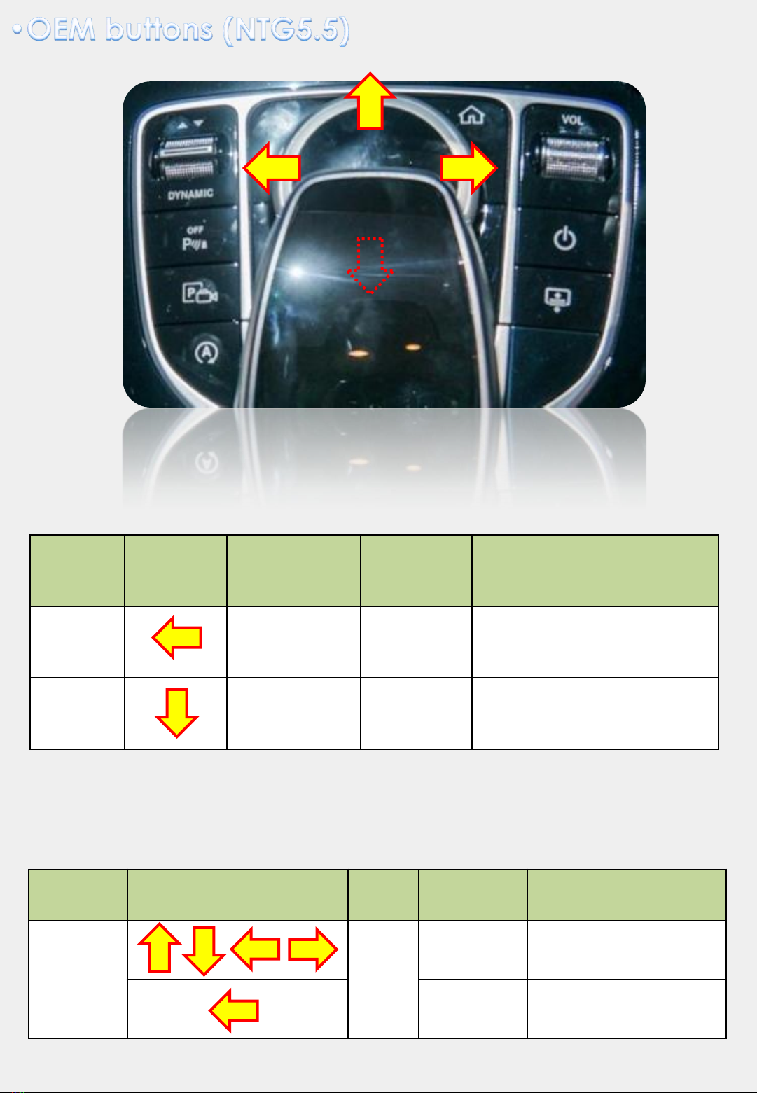
Sune Technology NTG5.5 User manual

Installation Manual
Interface for Mercedes Benz
NTG5.5 & NTG6.0

Compatibility: Mercedes Benz NTG5.5
Components: Interface Main *1
Interface Input / Output specification:
Input:LVDS IN (Car System) *1
Analog RGB *1
CVBS(Front Camera) *1
CVBS(Rear Camera) *1
Output:LVDS OUT (Car System) *1
Power Spec:
Input Power: 8VDC ~ 18VDC
Consumption: 5WATT
Switch input mode:
1. External video sources skip function: Able to control input videos on and off
via Dip switches
2. Able to switch videos via the remote and button switch
3. Able to detect the rear view camera by CAN
2
1. High-resolution display through HDMI input
2. Control EXT devices(DVD/DTV) via Multi Media Touch GUI
3. Adjustable screen position of external device
4. Improved Screen Display(user-oriented interface)
5. Mode switching with OEM button
6. Power output for rear camera drive
7. Dynamic PAS(parking assistance system)

3
Power Cable
HPOWER0177
Main Board
QCPASS1352
CAN J BY J
HARETC0091
AV Cable
HAVCAB0062
MULTI Cable
HARETC0240
RGB Cable
HRGBCA0013
CAP T/S Cable
HTOUCH0028
Dual Fakra Cable
HLCDCA0058
UART Cable
HTOUCH0031
Button Cable
HARETC0001
IR Cable
HIRCAB0002
Rear Cable
HARETC0002
Remote Control
REMOTE0001
* Power/CAN/LVDS for NTG5.5
Single Fakra Cable
HAGPSC0003
Power/CAN cable
HPOWER0231
T/S Out Cable
HTOUCH0009
*Power/CAN/LVDS for NTG6.0 [OPTION]

PIN
FUNCTION
Dip S/W SELECT
1
RGB
OFF : RGB MODE
ON : RGB MODE SKIP
2
No Use
3
No Use
4
No Use
5
LCD Resolution
OFF : 1920 * 720
ON : 960 * 540
6
LCD TYPE(CAR MODEL)
* Only Support MNT
Without OEM T/S
OFF :
Without OEM T/S : C-CLASS(10”)
ON :
Without OEM T/S : E-CLASS(8.4”/12.3”), S-
CLASS(12.3”), C-CLASS(7”)
7
REAR CAMERA
OFF : OEM Rear Camera Mode
ON : Ext. Rear Camera Mode
8
OEM Touch Screen
* Only Support MNT
Without OEM T/S
OFF : Always set to OFF
4
* ON : DOWN / OFF : UP
Please make sure to disconnect the power cable
of the interface and reconnect the power cable
again to apply the dip switch changes.

5
Key
FUNCTION
POWER & PIP N/C
MENU Activating OSD menu
OK Making a selection, changing image display
▲Moving upward
▼Moving downward
◀
Moving leftward
(If you press this button 2 seconds long, you can access the
factory mode)
▶
Moving rightward
(If you press this button 2 seconds long, you can reset all the
data about user environment)

PARK
PAS TYPE: Select parking line type.
- NOT USED: Do not use parking line
- PAS ON: Use Flexible Parking Lines
- PAS OFF: Use fixed parking line
PAS SETUP: You can move the position of parking line.
REAR TYPE : Choose rear camera recognition.
- CAN : By connecting to “CAN” cable of the car gear, changing to rear camera
mode when shifting into reverse. (Connect “CAN” cable of the power cable to the
“CAN” cable of the car gear)
- LAMP : By connecting to the rear lamp of the car, switch to rear camera mode
when shifting into rear. (Connect “Rear-C” cable of the power cable to the rear
lamp of the car)
SAFE ENABLE : If it is enable, HDMI, RGB, and A/V mode doesn’t show up while
driving. (Default : OFF)
RADAR ENABLE: Set the parking distance alarm sensor to ON/OFF.
IMAGE
H-POSITION: Move the screen left and right.
V-POSITION: Move the screen up and down.
H-SIZE (NAVI): Adjust the left and right size of
navigation.
IMAGE
PARK
UTIL
INFO
H-POSITION
V-POSITION
H-SIZE(NAVI)
Menu of FACTORY
MENU to Return SEL to Select/Save
IMAGE
PARK
UTIL1
UTIL2
INFO
PAS TYPE
PAS SETUP
REAR TYPE
SAFE ENABLE
RADAR ENABLE
Menu of FACTORY
MENU to Return SEL to Select/Save
6

UTIL1
AVOUT SELECT:
Select audio channel transmitted through AUX (HDMI,
AV)
AUTO FCAM TIME:
Front camera operation time adjustment
FCAM FUNC:
Select front camera display (ORI. FCAM/EXT. FCAM)
NAVI MODEL: RGB navigation setting
HDMI MODEL: HDMI device setting
FACTORY RESET: Factory mode reset
UTIL2
REMOTE DATA:
Select model to control the DVD and DTV device
REMOTE CONTROL: YES / NO
IR MEMORY: Register remote memory of DTV, DVD
CALIBRATE: Shows when Cap. T/S not connected
(Dip#8 OFF)
CTOUCH TYPE: Shows when Cap. T/S connected
(Dip#8 OFF)
MODE BUTTON: YES / NO
IMAGE
PARK
UTIL1
UTIL2
INFO
AVOUT SELECT
AUTO FCAM TIME
FCAM FUNC
NAVI MODEL
HDMI MODEL
FACTORY RESET
Menu of FACTORY
MENU to Return SEL to Select/Save
IMAGE
PARK
UTIL1
UTIL2
INFO
REMOTE DATA
REMOTE CONTROL
IR MEMORY
CALIBRATE/CTOUCH TYPE
MODE BUTTON
Menu of FACTORY
MENU to Return SEL to Select/Save
7
System version information
IMAGE
PARK
UTIL1
UTIL2
INFO
SYSTEM VERSION
(MAIN -180719)
(MCU : P1.8.08.16
Menu of FACTORY
MENU to Return SEL to Select/Save

8
* Press high lighted OEM button for 3 seconds long to mode switch

Monitor
Joy
shuttle
Direction
Mode
Pushing
Joy shuttle
Mode
12.3inch
Rear, Front
Camera
mode
Short
Ext. Camera <-> OEM
Screen
8inch
Rear, Front
Camera
mode
Short
Ext. Camera <-> OEM
Screen
9
1. Rear Camera Mode Switch
2. DVD, DTV OSD control
( OSD control remote will appear if the joy shuttle is moved to the left for a short time in DVD, DTV mode)
Monitor
Direction
Mode
Pushing
Joy shuttle
Movement
12.3inch/
8inch
DVD
DTV
Short
UP,DOWN,LEFT,RIGHT
Long
Select

10
* Press high lighted OEM button for 3 seconds long to mode switch
•Rear Camera Mode Switch :
Short press below high lighted button in Ext. rear camera mode to switch OEM screen

11
* Side View for QLI-W213

12
RGB
NAVIGATION
External Cap.
touch screen
Supplied Res. touch
Cable
External Res.
touch screen
UART Touch Cable
Pin assignment
RX
TX
GND
* Please refer next
page for power/CAN
connection
Power
CAN in/out
Rear camera input *1
Front camera input *1
Supplied Cap.
touch cable
* Please refer next
page for LVDS in/out
connection
* Side View
* Side View

13
QDIS doesn’t supply this cable

14
LCD cable
1: Remove the original green LCD cable.
2: Connect the original LVDS cable with the interface “LVDS IN” cable. Connect the
other side of the “LVDS IN” cable with the interface input “LVDS IN ”.
3: Connect the interface “LVDS OUT” cable with the video interface input “VIDEO OUT”
and the other side with Command screen.

15
Find the beige color connector
behind the command
Remove the right wire from the
beige color connector and
connect it to QDIS adapter
Then, connect QDIS adapter to
LVDS out of the interface
Connect the supplied LVDS IN wire to
the right side of beige color
connector.
Then, another side of connector shall
be connected to the LVDS IN of the
interface
OEM
QDIS LVDS IN
cable
10.25 inch monitor command
QDIS adapter

16
Find the red color double Fakra
connector behind the command
Please use A Class LCD J by J cable
10.25inch monitor command
OEM Cable
OEM Angle
type double
Fakra
connector
OEM HU

17
Find a bunch of
cables from the
command behind
Take away the black
connector cover
Connect the OEM
connector to the
supplied CAN IN/OUT
Remove the black
connector marked
with a red circle
Put the black connector
cover onto the supplied
CAN IN/OUT cable
Reconnect the supplied
cable where the black
connector was removed.
* CAN IN/OUT connection for NTG5.5
- Find a bunch of wires from the command behind the monitor as shown below
GROUND
B+
* Connect the black ground wire
of the supplied power cable to
the brown OEM wire
* Connect the red B+ wire of the
supplied power cable to the
orange/blue OEM wire

18
* CAN IN/OUT Connection for NTG6.0:
Pleas find a bunch of wires from the command behind the monitor as shown below
(Black Connector)
-> Now we have Power/CAN Jack by Jack cable, so no just connect with plug and
play, no need to wire, please follow below steps:
1. Disconnect the OEM power cable from the backside of command
2. Connect the OEM cable to the female connector of supplied power cable
3. Connect the male connector of supplied power cable to the backside of monitor
POWER CABLE
HPOWER0231
❶
❷
❸

Q. I cannot change mode
A. Check connection of Ground cable and IR Cable. Check LED lamp is on, if not
check connection of POWER cable.
Q. All I got on the screen is black.
A. Check second LED lamp of the interface is on, if not, check A/V sources
connected are working well. (Second lamp indicates AV sources connected works
well) Check interface connection has been done well.
Q. Displayed image color is not proper (too dark or unsuitable color)
A. Press
▶
button on the remote control for 2 seconds and check how it goes, if it
does not work, inform to manufacturer.
Q. I cannot watch the rear camera on the screen
A. Set the DIP switch #7 as state “ON”.
Q. Set mode not appear
A. Check DIP Switch.
Q. OEM image is not displayed.
A. Check interface’s LCD In/Out cable connection. If the status keeps on, inform to
manufacturer.
Q. Screen only displays white color.
A. Check LCD out cable is connected well, if this status keeps, inform to
manufacturer.
Q. If no image is shown on screen after connecting CAN wire with Park gear.
A. Go on the “FACTORY MODE”, check “UTIL-Rear Select”. If “LAMP”, change the
setting as “CAN” with the remote control. (
※
when connecting Rear-C wire of LAMP
power cable to Backup lights, Setting should be like this / CAN : if controlling rear
camera with CAN wire)
19

20
Copyright ⓒ2019 by SUNE TECHNOLOGY
SUNE TECHNOLOGY CO.,LTD
No.9,Lane 606,Anping Rd,Tainan City 70849,TAIWAN TEL:+88662292246 FAX:
+88662288104
Http://www.sune-tech.com
Shop http://www.carnavi-tech.com
SKYPE:sune_tech or hsin_han99
This manual suits for next models
1
Table of contents
Other Sune Technology Automobile Accessories manuals

Sune Technology
Sune Technology QVL-A4L-V7.3 User manual

Sune Technology
Sune Technology SUNE10-NTG55 User manual

Sune Technology
Sune Technology HD-LEXUS User manual

Sune Technology
Sune Technology QHLI-LVTX-5CH-ECLIPSE User manual

Sune Technology
Sune Technology HMDI-3S-MNT User manual

Sune Technology
Sune Technology NTG6 User manual

Sune Technology
Sune Technology SUNE10 PLUS-NTG5 User manual

Sune Technology
Sune Technology HD-CAYENNE User manual

Sune Technology
Sune Technology SUNE10 VELAR User manual

Sune Technology
Sune Technology QPI-BM12 Manual