manuals.online logo
Brands
  1. Home
  2. •
  3. Brands
  4. •
  5. Sunricher
  6. •
  7. Lighting Equipment
  8. •
  9. Sunricher SR-SBP2801-BLE-E User manual

Sunricher SR-SBP2801-BLE-E User manual

®
SR-SBP2801-BLE-E Bluetooth Pushbutton Transmitter Module
Important: Read All Instructions Prior to Installation
1.1 Basic functionality
SR-SBP2801-BLE-E are wireless push switches for lighting, building or industrial automation control systems
using Bluetooth® low energy technology.
SR-SBP2801-BLE-E is mechanically compatible with existing switch elements enabling quick integration into a
wide range of designs. Key applications are wall-mounted or portable switches either with up to two rockers or
up to four push buttons.
SR-SBP2801-BLE-E pushbutton transmitters are battery-powered. When the push button is pushed down or
released, a radio telegram according to the Bluetooth® low energy standard is transmitted. This radio telegram
transmits the status of all four push buttons when the push button was pushed down or released. SR-SBP2801-
BLE-E radio telegrams are protected with AES-128 security based on a device-unique private key.
SR-SBP2801-BLE-E is available in the following variants:
1.SR-SBP2801-BLE-E
Stand-alone module without additional components for OEM integration
2.SR-SBP2801K4-BLE-E
SR-SBP2801-BLE-E integrated into European-style single / double rocker wall switch housing
3.SR-SBP2801K4-BLE-E(US)
SR-SBP2801-BLE-E integrated into US-style single or double rocker pad housing
The term “SR-SBP2801-BLE-E” as used in this document applies to all product variants unless otherwise
mentioned. Figure 1 below shows from left to right the SR-SBP2801-BLE-E module, the European wall
switches and the US-style rocker pads.
1. General description
Figure 1 – Standalone Module, European Wall Switches and US-style rocker pads
1.2 Technical data
Dimensions
Weight
Security
Power Supply
Button Inputs
Communication Range (guidance only)
Max. transmit power measured
Antenna
Communication Standard
Data Rate and Modulation
Radio Channels (default)
Configuration Interface
Device Identification
Radio Frequency (min / max)
AES128 (CBC Mode) with Sequence Code
20 g +/- 1g
3VDC (1*CR2430 Battery)
0.4dBm / 1.1mW
Integrated PCB antenna
75 m ideal line of sight / 10 m indoor environment
Up to four buttons or two rockers
40.0 x 40.0 x 11.2 mm
Bluetooth Low Energy (BLE)
Unique 48 Bit Device ID (factory programmed)
1 Mbit/s GFSK (default) / 2 Mbit GFSK (NFC option)
CH 37 / 38 / 39 (2402 MHz / 2426 MHz / 2480 MHZ)
NFC Forum Type 2 Tag (ISO/IEC 14443 Part 2 and 3)
2402 MHz / 2480 MHZ
1.3 Environmental conditions
Operating Temperature
Storage Temperature
Humidity
-25°C ... 65°C
0% to 95% r.h. (non-condensing)
-25°C ... 65°C
2. Functional information
2.1 Product overview
The pushbutton transmitter module SR-SBP2801-BLE-E from Sunricher enables the implementation of
wireless remote controls. It transmits Bluetooth Low Energy (BLE) data telegrams where the required energy is
provided by battery.
The SR-SBP2801-BLE-E product outline with key functional components is shown in Figure 2 below.
2.2 Basic functionality
When the push button is pushed down, a BLE radio telegram is transmitted which identifies the action (pressed
or not pressed) and the status of the four button contacts. Releasing the push button similarly transmits a
different radio telegram.
SR-SBP2801-BLE-E devices contain 4 button contacts which are pushed by an appropriate push button,
switch rocker or a similar construction mounted onto the device.
Button Contact
Snap-in and rotation axis for
pushbuttons or switch rocker
Figure 2 – SR-SBP2801-BLE-E Product Outline
By factory default, this module can not work with those platforms which have integrated
EnOcean switch, to enable this module to work with those platforms and get the same
functionality as the EnOcean switch, please execute the following steps:
Remove the rocker(s) and the switch housing from the SR-SBP2801-BLE-E module. Then,
all four button contacts (A0, A1, B0 and B1) have to be pressed and held at the same time
for over 10 seconds.
How to get the same functionality as EnOcean Switch and replace it
By identifying these different telegrams types and measuring the time between pushing and releasing of the
button, it is possible to distinguish between “Long” and “Short” button contact presses. This enables simple
implementation of applications such as dimming control or blinds control including slat action.
It is therefore possible to distinguish between radio telegrams sent when the button was pushed and radio
telegrams sent when the button was released.
2.3 Functional block diagram
Figure 3 – Functional block diagram of SR-SBP2801-BLE-E
Processor
Determines the status of the button contacts, encodes this status into a data word, generates the proper radio
telegram structure and sends it to the radio transmitter
RF transmitter
Transmits the data in the form of a series of short 2.4 GHz Bluetooth Low Energy radio telegrams using the
integrated antenna
NFC interface
Allows reading and writing certain product parameters using an NFC compliant reader /
writer supporting NFC Forum Type 2 tags (as specified by ISO/IEC 14443 Part 2 and 3).
2.4 User Interface
SR-SBP2801-BLE-E devices provide four button contacts. They
are grouped into two channels
(Channel A and Channel B) each containing two button contacts
(State O and State I).
The state of all four button contacts (pressed or not pressed) is
transmitted together with a unique device identification (48 Bit
device ID) whenever the energy bow is pushed or re- leased.
Figure 4 below shows the arrangement of the four button
contacts and their designation:
3. Telegram transmission
3.1 Radio channel parameters
SR-SBP2801-BLE-E transmits Bluetooth Low Energy (BLE) advertising telegrams within the 2.4 GHz
radio frequency band (2402MHz … 2480MHz).
By default, SR-SBP2801-BLE-E will use the three BLE advertising channels (BLE Channel 37, 38 and
39) defined for transmission. The transmission of a radio telegram on these three advertising channels is
called an Advertising Event.
Use of different radio channels within the frequency band from 2402 MHz to 2480 MHz is possible, see chapter
6.7.10.
The initialization value for data whitening is set as follows:
1.For BLE channels is set according to specification (value = radio channel)
2.For the custom radio channels the initialization value is equal to the offset from 2400 MHZ (e.g. value = 3 for
2403 MHz)
Table 1 below summarizes radio channels supported by SR-SBP2801-BLE-E.
Radio Channel
37
0
1
10
38
11
12
36
39
40
41
77
78
Frequency
2402 MHZ
2404 MHZ
2406 MHZ
2424 MHZ
2426 MHZ
2428 MHZ
2430 MHZ
2478 MHZ
2480 MHZ
2403 MHZ
2405 MHZ
2477 MHZ
2479 MHZ
Channel Type
BLE Advertising Channel
BLE Data Channel
BLE Data Channel
BLE Data Channel
BLE Advertising Channel
BLE Data Channel
BLE Data Channel
BLE Data Channel
BLE Advertising Channel
Custom Radio Channel
BLE Radio Channels
Custom Radio Channels
...
...
...
Table 1 – SR-SBP2801-BLE-E supported radio channels
A B
O
I
CHANNEL
STATE
Figure 4 – Button contact designation
Push
Button Battery
CH 37 CH 38 CH 39 INTERVAL
(20ms or 10ms ) CH 37 CH 38 CH 39 INTERVAL
(20ms or 10ms ) CH 37 CH 38 CH 39
Figure 5 – Default radio transmission sequence
3.3 User-defined radio transmission sequences
In certain situations, it might be desirable to transmit radio telegrams on channels other than the three
advertising channels.
SR-SBP2801-BLE-E therefore allows to select the radio channels to be used for the transmission of data
telegrams and commissioning telegrams. The following transmission modes are supported:
1.Both commissioning telegrams and data telegrams are transmitted on the advertising channels as three
advertising events. This is the default configuration and described in chapter 3.2 above.
2.Commissioning telegrams are transmitted on the advertising channels as three advertising events while data
telegrams are transmitted in a user-defined sequence as described below.
3.Both commissioning and data telegrams are transmitted in a user-defined sequence as described below.
The selection of the transmission mode is done using the VARIANT register of the NFC configuration interface
as described in chapter 6.7.9.
3.3.1 Supported radio transmission sequences
SR-SBP2801-BLE-E supports the following user-defined sequences:
1.Three channel sequence
This sequence is similar to the default Advertising Event with the difference that the user can select the radio
channels to be used. The three-channel sequence is described in chapter 3.3.2 below.
2.Two channel sequence
In this sequence the radio telegram is transmitted using four transmissions on two radio channels. It is
described in chapter 3.3.3 below.
3.One channel sequence
In this sequence the radio telegram is transmitted using six transmissions on one radio channel. It is described
in chapter 3.3.4 below.
The selection of user-defined radio transmission sequences is made via the VARIANT register of the NFC
configuration interface, please see chapter 6.7.9.
3.3.2 Three-channel radio transmission sequence
The three-channel radio transmission sequence is similar to the default transmission sequence. The difference
is that the radio channels (BLE Channel 37, 38 and 39 in the default transmission sequence) can be selected
using the registers TX_CHANNEL1, TX_CHANNEL2 and TX_CHANNEL3.
The SR-SBP2801-BLE-E telegram will in this mode be transmitted on the radio channel selected by
TX_CHANNEL1 first, immediately followed by a transmission on the radio channel selected by TX_CHANNEL2
and a transmission on the radio channel selected by TX_CHANNEL3.
This transmission sequence will be sent three times in total as shown in Figure 6 below.
The default interval between the advertising events is 20 ms. Starting with product version DC-06 it is possible
to reduce this interval to 10 ms via the NFC configuration interface. See chapter 6.7.9 for details.
TX_CHANNEL1 TX_CHANNEL2 TX_CHANNEL3
INTERVAL
(20ms or 10ms )
TX_CHANNEL1 TX_CHANNEL2 TX_CHANNEL3 TX_CHANNEL1 TX_CHANNEL2 TX_CHANNEL3
INTERVAL
(20ms or 10ms )
Figure 6 – Three channel radio transmission sequence
The format of TX_CHANNEL1, TX_CHANNEL2 and TX_CHANNEL3 is described in chapter 6.7.10.
3.3.3 Two-channel radio transmission sequence
The two-channel radio transmission sequence removes transmission on the third radio channel (selected by
TX_CHANNEL3) and instead repeats the transmission once more (four times in total).
The SR-SBP2801-BLE-E telegram will in this mode be transmitted on the radio channel selected by
TX_CHANNEL1 first, immediately followed by a transmission on the radio channel selected by
TX_CHANNEL2.
This two-channel transmission sequence will be sent four times in total as shown in Figure 7 below.
The default interval between the advertising events is 20 ms. Starting with product version DC-06 it is possible
to reduce this interval to 10 ms via the NFC configuration interface. See chapter 6.7.9 for details.
Figure 7 – Two channel radio transmission sequence
TX_CHANNEL1
INTERVAL
(20ms or 10ms )
TX_CHANNEL1
INTERVAL
(20ms or 10ms )
TX_CHANNEL1
INTERVAL
(20ms or 10ms )
TX_CHANNEL1
INTERVAL
(20ms or 10ms )
TX_CHANNEL1
INTERVAL
(20ms or 10ms )
TX_CHANNEL1
Figure 8 – Single channel radio transmission sequence
TX_CHANNEL1
INTERVAL
(20ms or 10ms )
TX_CHANNEL2 TX_CHANNEL1
INTERVAL
(20ms or 10ms )
TX_CHANNEL2 TX_CHANNEL1
INTERVAL
(20ms or 10ms )
TX_CHANNEL2 TX_CHANNEL1 TX_CHANNEL2
3.3.4 Single-channel radio transmission sequence
The single-channel radio transmission sequence removes transmission on the second and third radio channel
(selected by TX_CHANNEL2 and TX_CHANNEL3 respectively), i.e. all transmissions will be on the radio
channel selected by TX_CHANNEL1.
The SR-SBP2801-BLE-E telegram will be sent six times on this radio channel as shown in Figure 8 below.
The default interval between the advertising events is 20 ms. Starting with product version DC-06 it is possible
to reduce this interval to 10 ms via the NFC configuration interface. See chapter 6.7.9 for details.
The format of TX_CHANNEL1 is described in chapter 6.7.10.
4. Telegram format
SR-SBP2801-BLE-E transmits Bluetooth Low Energy (BLE) radio telegrams in the 2.4 GHz band. For detailed
information about the Bluetooth Low Energy standard, please refer to the applicable specifications.
Figure 9 below summarizes the BLE frame structure.
Figure 9 – BLE frame structure
The content of these fields is described in more detail below.
The 4 byte BLE Access Address identifies the radio telegram type. For advertising frames, the value of the
Access Address is always set to 0x8E89BED6.
4.3 Header
The BLE Header identifies certain radio telegram parameters. Figure 10 below shows the structure of the BLE
header.
4.1 Preamble
The BLE Preamble is 1 byte long and identifies the start of the BLE frame. The value of the BLE Preamble is
always set to 0xAA.
4.2 Access Address
3.2 Default radio transmission sequence
SR-SBP2801-BLE-E transmits telegrams in its standard configuration by using so-called Advertising
Events.
An advertising event is defined as the transmission of the same radio telegram on all selected radio channels
(by default this would be on BLE Channel 37, 38 and 39) one after another with minimum delay in between.
For reliability reasons, SR-SBP2801-BLE-E will send several (minimum two, maximum three) advertising
events for each button input. The resulting transmission sequence is shown in Figure 5 below.
The default interval between the advertising events is 20 ms. Starting with product version DC-06 it is possible
to reduce this interval to 10 ms via the NFC configuration interface. See chapter 6.7.9 for details.
4.4 Source address
The 6 byte BLE Source Address (MAC address) uniquely identifies each SR-SBP2801-BLE-E product. SR-
SBP2801-BLE-E supports two source address modes:
1. Static Source Address mode (default)
In this mode, the source address is constant (but its lower 32 bit can be configured via NFC interface)
2. Resolvable Private Address mode (NFC configurable option)
In this mode, the source address changes for each transmission
By default, SR-SBP2801-BLE-E uses Static Source Address mode. Private Resolvable Address mode can be
selected by setting the Private Source Address flag in the Configuration register (see chapter 6.7.3) to 0b1.
These two address modes are described in the following chapters.
4.4.1 Static source address mode
By default, SR-SBP2801-BLE-E uses static source addresses meaning that the source address is constant
during normal operation. The static source address can be read and configured (written) via NFC as described
in chapter 6.
The structure of SR-SBP2801-BLE-E static addresses is as follows:
1.The upper 2 bytes of the source address are used to identify the device type and set to 0xE215 for all SR-
SBP2801-BLE-E devices (to designate Sunricher SBP 2801 device type). These two bytes cannot be changed.
2.The lower 4 bytes are uniquely assigned to each device. They can be changed using the NFC configuration
interface as described in chapter 6.7.4
Figure 11 below illustrates the static address structure used by SR-SBP2801-BLE-E.
Figure 11 – BLE static source address structure
4.4.2 Resolvable private address mode
For some applications it is desirable to obfuscate the origins of SR-SBP2801-BLE-E data telegrams in order to
prevent tracking of its radio transmissions. This can be achieved by using resolvable private addresses (RPA)
as defined in the Bluetooth Core Specification.
SR-SBP2801-BLE-E can be configured to use resolvable private addresses by setting the RPA ADDRESS
MODE flag within the Configuration register (described in chapter 6.7.3) to 0b1.
When using resolvable private addresses, the address used by SR-SBP2801-BLE-E is modified (rotated)
according to a defined scheme which on one hand precludes determining the device identity by unauthorized
receivers while allowing authorized receivers (sharing a specific security key with SR-SBP2801-BLE-E) to do
so.
The shared security key – which has to be known by both SR-SBP2801-BLE-E and the authorized receiver – is
called the Identity Resolution Key (IRK). SR-SBP2801-BLE-E uses its device-unique random key as identity
resolution key. This key can be modified if needed via the NFC configuration interface as described in chapter
6.7.5.
For each data telegram transmitted by SR-SBP2801-BLE-E (i.e. for every button push or release), a new
Figure 12 – BLE resolvable private address structure
The prand value is encrypted using the IRK. The lowest 24 bit of the result (encrypted val- ue) are then used as
hash. The concatenation of 24 bit prand and 24 bit hash will be transmitted as 48 bit private resolvable source
address.
The receiver maintains a list of IRK for all transmitters that have been commissioned to work with it.
Whenever the receiver receives a data telegram with a resolvable private address (identified by the most
significant bits of the address field being set to 0b10), it will itself generate a 24 bit hash from the 24 bit prand
sequentially using each IRK known to it (i.e. the IRK of each device that has been learned into it).
If an IRK matches (i.e. when prand is encoded with the IRK then the result matches hash), then the receiver has
established the IRK used by the transmitter and thereby the identity of the transmitter.
So conceptually the IRK takes the role of the device address of the transmitter while prand and hash provide a
mechanism for the receiver to select the correct IRK among the set of IRK known to it.
This mechanism is illustrated in Figure 13 below.
Refer to Appendix B for an example of resolving a resolvable private address.
Note that commissioning telegrams (as described in chapter 5.3.2) always use static source addresses (as
described in chapter 4.4.1) since they establish the device identity and contain the IRK in the payload.
4.5 Check Sum
The 3 byte BLE Check Sum is used to verify data integrity of received BLE radio telegrams. It is calculated as
CRC (cyclic redundancy check) of the BLE Header, Source Address and Payload fields.
4.6 Telegram payload
SR-SBP2801-BLE-E can transmit two types of telegrams:
1.Data telegrams
The payload of data telegrams contains the switch status together with optional data
Figure 13 – Resolving private addresses
Figure 10 – BLE header structure
resolvable private address is generated. The 48 bit address field of such resolvable private address is split into
two sub-fields:
1.prand
This field contains a random number which always starts (two most significant bits) with 0b10. The prand value
is changed for each telegram that is transmitted. Individual advertising events used to transmit one telegram
(as described in chapter 3) use the same prand value.
2.hash
This field contains a verification value (hash) generated from prand using the IRK The structure of a resolvable
private address is shown in Figure 12 below.
(if applicable), the current sequence counter value and the resulting authentication signature
2.Commissioning telegrams
The payload of commissioning telegrams contains the private security key as well as the current value of the
sequence counter and the device address
The payload structure of both telegram types is described in the following chapters.
4.6.1 Data telegram payload
The payload of data telegrams is 13 … 17 bytes long (depending on the size of the Optional
Data field) and consists of the following fields:
1.Length (1 byte)
The Length field specifies the combined length of the following fields. The content of the field depends on the
size of the Optional Data field (which can be 0 / 1 / 2 or 4 byte). The resulting Length setting would be 12 / 13 /
14 or 16 byte (0x0C / 0x0D /
0x0E / 0x10) respectively
2.Type (1 byte)
The Type field identifies the data type used for this telegram. For SR-SBP2801-BLE-E data telegrams, this field
is always set to 0xFF to designate manufacturer-specific data field
3.Manufacturer ID (2 byte)
The Manufacturer ID field is used to identify the manufacturer of BLE devices based on assigned numbers.
Sunricher has been assigned 0x0A78 as manufacturer ID code.
The Manufacturer ID can be changed via the NFC configuration interface as described in chapter 6.7.7.
4.Sequence Counter (4 byte)
The Sequence Counter is a continuously incrementing counter used for security processing. It is initialized to 0
at the time of production and incremented for each telegram (data telegram or commissioning telegram) sent.
5.Switch Status (1 byte)
The Switch Status field reports the button action. The encoding of this field is described in chapter 4.6.2.
6.Optional Data (0 / 1 / 2 or 4 byte)
SR-SBP2801-BLE-E provides the option to transmit additional user-defined data within each data telegram as
described in chapter 6.7.8.
7.Security Signature (4 byte)
The Security Signature is used to authenticate SR-SBP2801-BLE-E radio telegrams as described in chapter
4.6.3
Figure 14 below illustrates the data telegram payload.
Figure 14 – Data telegram payload structure
4.6.2 Button action encoding
The Switch Status field within the data telegram payload identifies the SR-SBP2801-BLE-E button action
(button push or release). SR-SBP2801-BLE-E uses the following sequence to identify and transmit button
contact status:
1. Determine direction of the button movement (Push Action or Release Action)
2. Read input status of all button contacts
3. Calculate data payload
4. Calculate security signature
In SR-SBP2801-BLE-E, the type of action (Press Action or Release Action) is indicated by Bit 0 (button). If a
button contact has been actuated during Press Action or Release Action, then this is indicated by the according
status bit set to ‘1’.
Note that all contacts that were pressed during Press Action will be released during Release Action. The case of
continuing to hold one (or several) button contacts during Release Action is mechanically not possible.
Figure 15 - SR-SBP2801-BLE-E button action encoding
4.6.3 Commissioning telegram payload
The payload of commissioning telegrams is 30 bytes long and consists of the following fields:
1.Length (1 byte)
The Length field specifies the combined length of the following fields. For SR-SBP2801-BLE-E
commissioning telegrams, this field is set to 0x1D to indicate 29 byte of manufacturer-specific data.
Note: In product versions prior to DC-06 this field was incorrectly set to 0x1E.
2.Type (1 byte)
The Type field identifies the data type used for this telegram. This field is set to 0xFF
to indicate a “Manufacturer-specific Data” field
3.Manufacturer ID (2 byte)
The Manufacturer ID field is used to identify the manufacturer of BLE devices based on assigned numbers. By
default, this field is set to 0x0A78 (Sunricher). This field can be changed via the NFC configuration interface as
described in chapter
6.7.7.
4.Sequence Counter (4 byte)
The Sequence Counter is a continuously incrementing counter used for security processing. It is initialized to 0
at the time of production and incremented for each telegram (data telegram or commissioning telegram) sent.
5.Security Key (16 byte)
Each SR-SBP2801-BLE-E device contains its own 16 byte device-unique random security key which is
generated and programmed during manufacturing. It is transmitted during commissioning to enable the
receiver to authenticate SR-SBP2801-BLE-E data telegrams and used as IRK for the case of resolvable private
address mode
6.Static Source Address (6 byte)
The Static Source Address is used to uniquely identify each BLE device. It is transmitted as part of the BLE
frame as described in chapter 4.4.1.
Some devices (most notable all iOS-based products) however do not expose this address to their applications.
This makes it impossible to use such applications to
commission SR-SBP2801-BLE-E. The Static Source Address is therefore again transmitted as
part of the payload.
Figure 16 below illustrates the commissioning telegram payload.
Figure 16 – Commissioning telegram payload structure
4.7 SR-SBP2801-BLE-E data telegram authentication
SR-SBP2801-BLE-E implements telegram authentication for
transmitted data telegrams to ensure that only telegrams from
transmitters using a previously exchanged security key will be
accepted by the receiver. Authentication relies on a 32 bit
telegram signature which is calculated as shown in Figure 17
below and exchanged as part of the radio telegram.
Figure 17 – Telegram authentication flow
The button action encoding used by SR-SBP2801-BLE-E is shown Figure 15 in below.
Figure 18 – AES128 Nonce structure
The AES128 Nonce and the 128 bit device-unique security key are then used to calculate a 32 bit signature of
the authenticated telegram payload shown in Figure 19 below.
Figure 19 – Authenticated payload
The calculated 32 bit signature is then appended to the data telegram payload as shown in Figure 14 in chapter
4.6.
In addition to the RFC3610 standard itself, please consult also Appendix C for a step by step description of the
authentication process.
5. Commissioning
Commissioning is the process by which SR-SBP2801-BLE-E is learned into a receiver (actuator, controller,
gateway, etc.).
The following two tasks are required in this process:
1.Device identification
The receiver needs to know how to uniquely identify this specific SR-SBP2801-BLE-E device. This is achieved
by using a unique 48 Bit ID (Source Address) for each SR-SBP2801-BLE-E
device as described in chapter 4.4. In addition, up to 4 byte of Optional Data can be
configured as described in chapter 6.7.8
2.Security parameter exchange
The receiver needs to be able to authenticate radio telegrams from SR-SBP2801-BLE-E in order to ensure that
they originate from this specific device and have not been modified as described in chapter 4.6.3. This is
achieved by exchanging a 128 Bit random security key used by SR-SBP2801-BLE-E to authenticate its radio
telegrams.
SR-SBP2801-BLE-E provides the following options for these tasks:
1.NFC-based commissioning
The SR-SBP2801-BLE-E parameters are read by a suitable commissioning tool (e.g. NFC
smartphone with suitable software) which is already part of the network into which
SR-SBP2801-BLE-E will be commissioned. The commissioning tool then communicates these parameters to
the intended receiver of SR-SBP2801-BLE-E radio telegrams. NFC-based commissioning is described in
chapter 6
2.Camera-based commissioning
Each SR-SBP2801-BLE-E module contains an optically readable QR Code which identifies its
ID and its security key. This QR code can be read by a by a suitable commissioning tool (e.g. smart phone)
which is already part of the network into which SR-SBP2801-BLE-E will be commissioned. The commissioning
tool then communicates these parameters to the intended receiver of SR-SBP2801-BLE-E radio telegrams.
The QR code structure is described in chapter 7.2.
3.Radio-based commissioning
SR-SBP2801-BLE-E can communicate its parameters via special radio telegrams (commission- ing telegrams)
to the intended receiver. To do so, SR-SBP2801-BLE-E can be temporarily
placed into radio-based commissioning mode as described in chapter 5.3
5.1 NFC-based commissioning
All required SR-SBP2801-BLE-E parameters can be read via a suitable NFC reader and writer sup- porting the
ISO/IEC 14443 Part 2 and 3 standards. The actual NFC implementation in SBP
2801 uses a Mifare Ultralight tag.
Commissioning via NFC should follow these steps:
1. Unlock SR-SBP2801-BLE-E using the default NFC PIN code 0x0000E215
2. Read the SR-SBP2801-BLE-E Source Address, Security Key and Sequence Counter and configure the
receiver accordingly
3. Important: The pre-programmed random security key used by SR-SBP2801-BLE-E can be obtained both
from the product DMC code as described in chapter 5.2, from received commissioning telegrams as described
in chapter 5.3 and via the NFC interface.
For security-critical applications where unauthorized users could have physical access to the switch it is
therefore strongly recommended to change the security key to a new security key as part of the NFC-based
commissioning process. To do so, follow the procedure outlined in chapter 6.7.5.
For additional security, NFC read-out of the new security key can be disabled by setting the PRIVATE
SECURITY KEY flag in the Configuration register before setting the new security key.
This ensures that even persons knowing the correct PIN code to configure this specific switch cannot read out
the programmed new security key. Please verify that you have properly documented the new security key as
there is no possibility to retrieve this after it has been written.
4. Important: It is strongly recommended to disable radio-based commissioning after programming a new
security key. This ensures that the new security key cannot be read out by triggering a commissioning telegram
as described in chapter 5.3.
To disable radio-based commissioning, set the DISABLE LRN TELEGRAM flag in the Configuration register to
0b1, see chapter 6.7.3.
5. Important: You should always change the NFC PIN code from its default setting to a new NFC PIN code and
lock the NFC configuration interface. This step is mandatory to avoid access to the SR-SBP2801-BLE-E
configuration using the default PIN code.
Should you lose the new NFC PIN code then SR-SBP2801-BLE-E can be reset to factory mode
(with the default NFC PIN code) by means of a factory reset as described in chapter
5.4. For security reasons, this factory reset will always reset the security key to its pre-programmed value.
5.2 Camera-based commissioning
Sequence counter, source address and the remaining telegram data together form the in- put data for the
signature algorithm. This algorithm uses AES128 encryption based on the device-unique random security key
to generate a 32 bit signature which will be transmitted as part of the radio telegram.
The signature is therefore dependent both on the current value of the sequence counter, the device source
address and the telegram payload. Changing any of these three parameters will therefore result in a different
signature.
The receiver performs the same signature calculation based on sequence counter, source address and the
remaining telegram data of the received telegram using the security key it received from SR-SBP2801-BLE-E
during commissioning.
The receiver then compares the signature reported as part of the telegram with the signature it has calculated.
If these two signatures match, then the following statements are true:
1.Transmitter (SR-SBP2801-BLE-E) and receiver use the same security key
2.The message content (address, sequence counter, data) has not been modified
At this point, the receiver has validated that the message originates from a trusted transmitter (as identified by
its security key) and that its content is valid.
In order to avoid message replay (capture and retransmission of a valid message), it is required that the
receiver tracks the value of the sequence counter used by SR-SBP2801-BLE-E and only accepts messages
with higher sequence counter values (i.e. not accepts equal or lower sequence counter values for subsequent
telegrams).
4.7.1 Authentication implementation
SR-SBP2801-BLE-E implements data telegram authentication based on AES128 in CCM (Counter with CBC-
MAC) mode as described in IETF RFC3610. At the time of writing, the RFC3610 standard could be found here:
https://www.ietf.org/rfc/rfc3610.txt
The 13 Byte CCM Nonce (number used once – unique) initialization value is constructed as concatenation of 6
byte Source Address, 4 byte Sequence Counter and 3 bytes of value
0x00 (for padding).
Note that both Source Address and Sequence Counter use little endian format (least significant byte first).
Figure 18 below shows the structure of the AES128 Nonce.
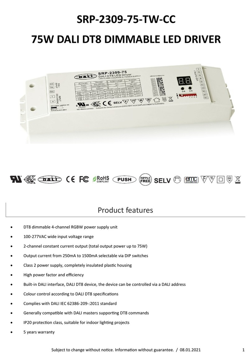
Figure 21 – Elatec TWN4 MultiTech Desktop NFC Reader
Each SR-SBP2801-BLE-E module contains an optically readable Commissioning Code implemented either as
Data Matrix Code or as QR Code depending on the device revision.
This Commissioning Code on the device label can be scanned by a suitable commissioning tool (e.g. smart
phone or PC with DMC / QR code reader) to read the static source address and the security key of the device.
The commissioning tool can the use this information to configure the intended receiver of
SR-SBP2801-BLE-E radio telegrams.
See chapter 7 for details of the commissioning code structure.
5.3 Radio-based commissioning
For cases where both NFC and camera-based commissioning are not feasible it is possible to set SR-
SBP2801-BLE-E into a specific mode where it transmits commissioning telegrams.
This functionality can be disabled via the NFC configuration interface by setting the DISABLE LRN TELEGRAM
flag in the Configuration register to 0b1 (see chapter 6.7.3).
Starting from product version DC-06, this functionality can also be disabled by means of a specific button press
(long press of A0 + A1 + B1), see chapter 5.3.4.
5.3.1 Commissioning mode entry
Commissioning mode is entered using a special button contact sequence. This is illustrated in Figure 20 below.
Figure 20 – Button sequence to enter radio-based commissioning mode
To enter commissioning mode, start by selecting one button contact of SR-SBP2801-BLE-E. Any button of SR-
SBP2801-BLE-E (A0, A1, B0, B1) can be used. This button is referred to as Button_X in Figure 20 above.
Next, execute the following long-short-long sequence:
1. Press and hold the selected button for more than 7 seconds before releasing it
2. Press the selected button quickly (hold for less than 2 seconds)
3. Press and hold the selected button again for more than 7 seconds before releasing it
Upon detection of this sequence, SR-SBP2801-BLE-E will enter commissioning mode if the DISABLE LRN
TELEGRAM flag in the Configuration register of the NFC interface is not set (0b0, default state).
If the DISABLE LRN TELEGRAM flag in the Configuration register of the NFC interface is set (0b1, configured
via NFC interface) then SR-SBP2801-BLE-E will not enter commissioning mode and transmit normal data
telegrams according to the button status.
5.3.2 Commissioning telegram transmission
SR-SBP2801-BLE-E will transmit a commissioning telegram (on the radio channels selected as described in
chapter 3.1) upon entering commissioning mode. The structure of the commissioning telegram is described in
chapter 4.6.3.
SR-SBP2801-BLE-E will continue to transmit commissioning telegrams whenever the button used for entry into
commissioning mode (Button_X) is pressed or released again.
5.3.3 Exit from commissioning mode
Pressing any key except the button used for entry into commissioning mode (Button_X) will cause SR-
SBP2801-BLE-E to stop transmitting commissioning telegrams and return to normal data telegram
transmission.
5.3.4 Disable commissioning mode
Starting with product version DC-06 it will be possible to disable commissioning mode in addition to using the
NFC interface also by means of a specific button input.
To do so, press button contacts A0, A1 and B1 and hold them for at least 10 seconds before releasing them.
Commissioning mode can be re-enabled by means of a factory reset as described below.
5.4 Factory reset
SR-SBP2801-BLE-E can be reset to its default settings by means of a factory reset.
This ensures that SR-SBP2801-BLE-E can be reset to a known configuration in case the
PIN for the NFC access has been lost or NFC access is not possible for other reasons
In order to execute such factory reset, the rocker(s) and switch housing have to be
removed from the SR-SBP2801-BLE-E module. Then, two diagonal button contacts (for
instance A0 and B1 or A1 and B0) have to be pressed and held at the same time for over 10
seconds.
Upon detecting this input, SR-SBP2801-BLE-E will restore the default settings of the
following items:
1.Static Source Address
2.Security Key and Security Key Write register
Both registers will be restored to the value of the factory-programmed security key
3.Manufacturer ID
The manufacturer ID will be reset to 0x0A78 (Sunricher)
4.NFC PIN Code
The NFC PIN Code will be reset to 0x0000E215
After such factory reset, Source Address and Security Key will again match the content of the DMC code on the
unit label as described in chapter 7.
In addition, SR-SBP2801-BLE-E will reset the following registers:
1.Configuration register (to 0x00)
2.Variant Register (to 0x00)
6. NFC interface
SR-SBP2801-BLE-E implements NFC Forum Type 2 Tag functionality as specified in the ISO/IEC 14443 Part 2
and 3 standards using an NXP NT3H2111 Mifare Ultralight tag.
This NFC functionality can be used to access (read and write) the SR-SBP2801-BLE-E configuration memory
and thereby configure the device as described in the following chapters.
Chapter 6.1 below gives an introduction to the NFC functionality and options to use the NFC interface.
For in-depth support for integrating the NXP NT3H2111 NFC functionality into PC or smartphone SW please
contact NXP technical support.
6.1 Using the NFC interface
Using the NFC interface requires the following:
1.NFC reader (either PC USB accessory or suitable smart phone / tablet)
2.NFC SW with read, write, PIN lock, PIN unlock and PIN change functionality
Sunricher recommends TWN4 (order code T4BT-FB2BEL2-SIMPL) from Elatec RFID Systems
(https://www.elatec-rfid.com/en/) as USB NFC reader. This reader is shown in Figure 21 below.
TWN4 can be configured as CDC / Virtual COM port and can then be accessed like any serial interface. It
provides all necessary commands for the NFC interface, specifically to:
1.Read data from configuration memory and write data to configuration memory
2.Authenticate the user (to allow read / write of protected memory) via 32 bit PIN
NFC functionality is also available in certain Android smart phones and tablets. NXP provides a SW framework
that can be used with Android devices and can advise regarding suitable tablets and smart phones.
NFC communication distance is for security reasons set to require direct contact between reader and switches
based on SR-SBP2801-BLE-E.
6.2 NFC interface functions
For a detailed description about the NFC functionality, please refer to the ISO/IEC 14443 standard.
For specific implementation aspects related to the NXP implementation in NT3H2111,
please refer to the NXP documentation which at the time of writing was available under this link:
https://www.nxp.com/docs/en/data-sheet/NT3H2111_2211.pdf
The following chapters summarize the different functions for reference purposes.
6.2.1 NFC interface state machine
Figure 22 below shows the overall state machine of the NFC interface.
Figure 22 – NFC interface state machine
6.2.2 IDLE state
IDLE is the waiting state after a Power-On Reset (POR), i.e. after the NFC tag has been introduced into the
magnetic field of the NFC reader.
The NFC tag exits the IDLE state towards the READY 1 state when either a REQA or a WUPA command is
received from the NFC reader. REQA and WUPA commands are transmitted by the NFC reader to determine
whether any cards are present within its working range.
Any other data received by the NFC tag while in IDLE state is discarded and the NFC tag will remain in IDLE
state.
6.2.3 READY 1 state
READY 1 is the first UID resolving state where the NFC tag resolves the first 3 bytes of the
7 byte UID using the ANTICOLLISION or SELECT commands for cascade level 1.
READY 1 state is exited after the SELECT command from cascade level 1 with the matching complete first part
of the UID has been executed. The NFC tag then proceeds into READY 2 state where the second part of the
UID is resolved.
6.2.4 READY 2 state
READY 2 is the second UID resolving state where the NFC tag resolves the remaining 4 bytes of the 7 byte UID
using the ANTICOLLISION or SELECT commands for cascade level 2.
READY 2 state is exited after the SELECT command from cascade level 2 with the matching complete part of
the UID has been executed. The NFC tag then proceeds into ACTIVE state where the application-related
commands can be executed.
6.2.5 ACTIVE state
ACTIVE state enables read and write accesses to unprotected memory.
If access to protected memory is required, then the tag can transition from the ACTIVE state to
AUTHENTICATED state by executing the PWD_AUTH command in conjunction with the correct 32 bit
password.
Figure 23 – NFC read command sequence
6.2.7 Write command
The WRITE command requires a start page
address and returns writes 4 bytes of data into
that page.
Figure 24 below shows the read command
sequence.
Figure 24 – NFC write command sequence
6.2.6 Read command
The READ command requires a start page
address, and returns the 16 bytes of four
NFC tag pages (where each page is 4 byte in
size).
For example, if the specified address is 03h
then pages 03h, 04h, 05h, 06h are returned.
Spe- cial conditions apply if the READ
command address is near the end of the
accessible
memory area.
Figure 23 below shows the read command
sequence.
6.2.8 Password authentication
(PWD_AUTH) command
The protected memory area can be accessed
only after successful password verification via
the PWD_AUTH command.
The PWD_AUTH command takes the
password as parameter and, if successful,
returns the password authentication
acknowledge, PACK.
Figure 25 below shows the password
authentication sequence. Figure 25 – Password authentication sequence
After successful authentication, the password can be changed by writing the new password to memory page
0xE5.
Note that a read access to page 0xE5 always return 0x00000000, i.e. it is not possible to read out the current
PIN code.
6.3 Using TWN4 as USB NFC reader
Elatec RFID Systems provides a PC software called “Director” as part of their software sup- port package. At
the time of writing, this was available from this address: https://www.elatec-rfid.com/en/download-
center/contact-form-twn4-devpack-sdk/
Figure 26 below shows the user interface of this software.
Figure 26 – User interface of TWN4 Director
By using this software, it is easily possible to generate the required serial commands that have to be sent via
CDC / Virtual COM port to TWN4 and understand the structure of the response that will be received back.
6.3.1 Useful commands
The following commands are especially useful:
1.SearchTag(maximum ID bytes)
Used to search for a connected tag and identify type and ID of such tag. This should always be used as first
operation ahead of any read / write / authenticate actions. Example: SearchTag(32)
2.NTAG_PwdAuth(32 bit password as hex bytes, 16 bit password_ack as hex bytes)
Used to authenticate access to the protected memory area
Example: NTAG_PwdAuth(0x00 0x00 0xE2 0x15, 0x00 0x00)
3.NTAG_Read(page)
Used to read one page of data
Example: NTAG_Read(0x04)
4.NTAG_Write(page, data)
Used to write one page of data
Example: NTAG_Write(0x40, 0x12 0x34 0x56 0x78)
5.NTAG_Write(0xE5, PIN Code)
Used to set a new pin code by writing to page 0xE5
Example: NTAG_Write(0xE5, 0x12 0x34 0x56 0x78)
6.3.2 Translation into binary data
In order to use these commands within a user application, they have to be translated into raw data. This can be
done by enabling the “Show Raw Data” feature in the command log of the Director software as shown in Figure
27 below.
Figure 27 – Enabling raw data display
This raw data can then be transmitted to TWN4 via a virtual COM port. TWN4 will respond to the request with
the corresponding response as shown in Figure 28 below.
Figure 28 – Binary data exchange
6.4 Configuration memory organization
The SR-SBP2801-BLE-E configuration
memory is divided into the following areas:
1.Public data
2.Protected data
In addition to that, SR-SBP2801-BLE-E
maintains a private configuration memory
region used to store default parameters and
confidential information which is not
accessible to the user.
Figure 29 below shows the configuration
memory structure used by SR-SBP2801-BLE-
E.
Figure 29 – Configuration memory structure
6.5 NFC memory address map
The NFC-accessible configuration memory is organized in memory pages where each memory page is 4 byte
wide. An NFC access reads 16 bytes (4 pages) or writes 4 bytes (one page). The addresses map of the
configuration memory is shown in Table 2 below. The byte order is little endian, i.e. byte 0 will be read first and
byte 3 last.
Area NFC Page Byte Offset Byte 0 (LSB) Byte 1 Byte 2 Byte 3 (MSB)
Public
Public
Public
Public
Public
Public
Public
Public
Public
Public
Public
Public
Public
Protected
Protected
Protected
Protected
Protected
Protected
Protected
Protected
Protected
Protected
Protected
Protected
Protected
Protected
Protected
Protected
Protected
Protected
Protected
Protected
0 (0x00)
…
3 (0x03)
4 (0x04)
5 (0x05)
6 (0x06)
7 (0x07)
8 (0x08)
9 (0x09)
10 (0x0A)
11 (0x0B)
12 (0x0C)
13 (0x0D)
14 (0x0E)
15 (0x0F)
16 (0x10)
17 (0x11)
18 (0x12)
19 (0x13)
20 (0x14)
…
23 (0x17)
24 (0x18)
25 (0x19)
…
31 (0x1F)
32 (0x20)
…
95 (0x5F)
96 (0x60)
…
225 (0x10)
229 (0xE5)
0
…
12
16
20
24
28
32
36
40
44
48
52
56
60
64
68
72
76
80
…
92
96
100
…
124
128
…
380
384
…
900
916
Public Memory Area
Reserved
Product Name
"SBP2801 "
Product ID Public
NFC Revision Manufacturer ID
Reserved
Hardware Revision
Software Revision
Static Source Address
Sequence Counter
Protected Memory Area
Configuration Variant Reserved
Opt Data 0 Opt Data 1 Opt Data 2 Opt Data 3
Product ID Write
Source ID Write
Manufacturer ID Write Reserved
Security Key Write
TX_CHANNEL1 TX_CHANNEL2 TX_CHANNEL3
Reserved
Reserved
Customer NFC Data
Reserved
PIN Code (Write Only)
Table 2 – Configuration memory address map
6.6 Public data
Public data can be read by any NFC-capable device supporting the ISO/IEC 14443 Part 2 and 3 standards. No
5.Optional Data register
This 4 byte register contains optional data that can be transmitted as part of all data telegrams, see chapter
4.6. Optional Data 0 is sent first, Optional Data 3 last.
6.Configuration register
This 1 byte register is used to configure the functional behavior of SR-SBP2801-BLE-E, see chapter 6.7.3
7.Variant register
This 1 byte register is used to configure the transmission behavior of SR-SBP2801-BLE-E, see chapter 6.7.9
8.Custom Radio Channel registers (TX_CHANNEL1, TX_CHANNEL2 and TX_CHANNEL3)
These 1 byte registers are used to configure the radio channels in custom transmis- sion mode of SR-
SBP2801-BLE-E, see chapter 6.7.10
9.Custom NFC Data
SR-SBP2801-BLE-E reserves 64 byte for customer-specific NFC data, see chapter 6.7.11
specific security measures are used to restrict read access to this data.
The following items are located in the public data area:
1.SR-SBP2801-BLE-E Product Name
This is always “SBP2801 ”
2.SR-SBP2801-BLE-E Product ID
This is an 8 byte field which is by default set to 0x0000000000000000.
Product ID and Manufacturer ID can be configured by the customer as required to identify his SR-SBP2801-
BLE-E based product, see chapter 6.7.7
3.SR-SBP2801-BLE-E Manufacturer ID
This is an 2 byte field used to identify the manufacturer of a BLE product, see chap- ter 4.6. This field is by
default set to 0x0A78(Sunricher).
Product ID and Manufacturer ID can be configured by the customer as required to identify his SR-SBP2801-
BLE-E based product, see chapter 6.7.7
4.SR-SBP2801-BLE-E Static Source Address
This is a 4 byte field containing the four least significant bytes (the two most significant bytes are always
0xE215) of the static source address used by SR-SBP2801-BLE-E, see chapter 4.4.1. Each SR-SBP2801-
BLE-E is pre-programmed with an individual static source address.
The Static Source Address can be configured by the customer as required to identify his SR-SBP2801-BLE-E
based product, see chapter 6.7.4
5.Hardware Revision, Software Revision and NFC Revision
These fields identify the device revision
6.Telegram sequence counter
This is a 4 byte field which is initialized to zero during manufacturing and incremented for each transmitted
telegram. Receivers shall never accept telegrams containing sequence counter values equal or less than
previously received values to avoid replay attacks.
Changing the Static Source Address, Manufacturer ID and Product ID fields is only possible via protected data
access as described below to prevent unauthorized modification.
For security reasons, the telegram sequence counter cannot be written or reset by any mechanism.
6.7 Protected data
The following items are located in the protected data area:
1.Source Address Write register
This 4 byte register is used to update the lower 4 byte of the Static Source Address, see chapter 6.7.4
2.Product ID Write register
This 8 byte register is used to update the Product ID, see chapter 6.7.7
3.Manufacturer ID Write register
This 4 byte register is used to update the Manufacturer ID, see chapter 6.7.7
4.Security Key Write register
This 16 byte register is used to update the security key used by SR-SBP2801-BLE-E, see chapter 6.7.5
6.7.1 PIN code
Protected data access is only possible after unlocking the configuration memory with the correct 32 bit PIN
code. By default, the protected area is locked and the default pin code for unlocking access is 0x0000E215.
The default pin code shall be changed to a user-defined value as part of the installation process. This can be
done by unlocking the NFC interface with the old PIN code and then writing the new PIN code to page 0xE5 as
described in chapter 6.3.1.
6.7.2 Configuration of product parameters
SR-SBP2801-BLE-E allows no direct modification of the following parameters:
1.Static Source Address
2.Product ID
3.Manufacturer ID
4.Security Key
In order to modify these parameters, the user has to write the new value into specific registers (Source Address
Write, Product ID Write, Manufacturer ID Write and Security Key Write) in the protected data area and set the
according Update flag in the Configuration register.
After that, the user has to push and release the button of the SR-SBP2801-BLE-E module.
6.7.3 Configuration register
The Configuration register is 1 byte wide and contains configuration flags. Figure 30 below shows the structure
of the Configuration register.
CONFIGURATION
Bit 7 Bit 6 Bit 5 Bit 4 Bit 3 Bit 2 Bit 1 Bit 0
OPTIONAL D ATA S IZE
DISAB LE LR N
TELEGRAM
RPA ADDRESS
MODE
PRIVATE
SECUR ITY KEY
UPD ATE
SECUR ITY KEY
UPD ATE
MAN ID
UPD ATE
SOURCE ID
Figure 30 – Configuration register structure
The Configuration register is used to select the length of optional data, to disable the transmission of
commissioning telegrams, to select resolvable private address mode, to disable NFC read-out of the security
key and to indicate an update of the security key, the manufacturer ID or the source ID.
6.7.4 Source Address Write register
The Source Address Write register is 4 byte wide and can be used to modify the lower 32 bit of the SR-
SBP2801-BLE-E Static Source Address. The upper 16 bit of the SR-SBP2801-BLE-E Static Source Address
are always fixed to 0xE215 to identify the device type. In order to do change the lower 32 bit of the Static
Source Address, follow these steps:
1. Write new source address into the Source Address Write register
2. Set the UPDATE SOURCE ID flag in the Configuration register to 0b1
3. Actuate (press and release) the button of SR-SBP2801-BLE-E
SR-SBP2801-BLE-E will determine that it should modify the Static Source Address based on the set- ting of the
Update Source ID flag and copy the value of the Source Address Write register
to the lower 32 bit of the Source Address register. After successful execution, SR-SBP2801-BLE-E will clear
the UPDATE SOURCE ID flag to 0b0.
6.7.5 Security Key Write register
The Security Key Write register is 16 byte wide and contains the device-unique random security key. The
factory programmed key can be replaced with a user defined key by fol- lowing these steps:
1. Write new security key into the Security Key Write register
Note that for security reasons, setting the Security Key to the following values is not possible:
•0x00000000000000000000000000000000
•0xFFFFFFFFFFFFFFFFFFFFFFFFFFFFFFFF
If the Security Key Write register is set to one of these values then no update of the Security Key will occur.
2. Set the UPDATE SECURITY KEY flag in the Configuration register to 0b1
3. If the key should be write-only (not readable after the key update) then set the Private Security Key flag in
the Configuration register to 0b1
4. Actuate (press and release) the button of SR-SBP2801-BLE-E
SR-SBP2801-BLE-E will determine that it should modify the security key based on the setting of the Update
Security Key flag and copy the value of the Security Key Write register to the Security Key register in private
memory. After successful execution, SR-SBP2801-BLE-E will clear the UPDATE SECURITY KEY flag to 0b0.
The protected memory is designed to support 1000 modifications of the security key.
Note that it is not possible to read the current security key via NFC if the Security Key Write register has been
accidentally overwritten or cleared via NFC write. In this case it is necessary to write a new security key (as
described above) or to reset the device to its de- fault security key by means of a factory reset.
6.7.6 Private Security Key mode
SR-SBP2801-BLE-E provides a private security key mode for applications requiring high security. In this mode,
it is possible to write a security key which subsequently is inaccessible via NFC and will not show up in
commissioning telegram. In both cases, the security key will be set to all zeros. The written security key thereby
is completely inaccessible externally.
To use private security key mode, set the PRIVATE SECURITY KEY flag in the Configuration register is to 0b1,
the Security Key Write register to the desired security key and the UP- DATE SECURITY KEY flag in the
Configuration register is to 0b1 and pushing the button.
The Security Key Write register will be cleared to 0x00000000000000000000000000000000 after successful
execution and the written security key will not be NFC readable (even for users having the correct PIN code). If
commissioning telegrams are enabled then the secu- rity key will be set to
0x00000000000000000000000000000000 there as well.
It is possible to return to Public (NFC-accessible) key mode by clearing the PRIVATE SECURI- TY KEY flag in
the Configuration register, setting the Security Key Write register to the desired security key and the UPDATE
SECURITY KEY flag in the Configuration register is to
0b1 and pushing the button.
The protected memory is designed to support 1000 modifications of the security key.
6.7.7 Product ID and Manufacturer ID Write register
The Product ID register is 8 byte wide and can be used to specify a publicly-accessible parameter (e.g. a user-
specific ID or name) that can be read by an NFC commissioning tool in order to determine the specific product
type.
The Manufacturer ID is 2 byte wide and specifies the manufacturer of a BLE product and is transmitted as part
of each BLE telegram. By default, the manufacturer ID is set to 0x0A78 (Sunricher) but it can be changed to a
different OEM identifier.
Product ID and Manufacturer ID can be changed by following these steps:
1. Write the desired Product ID (8 byte using HEX or ASCII encoding according to user choice) into the Product
ID Write register. Setting the Product ID register to
0x0000000000000000 will cause SR-SBP2801-BLE-E not to update the Product ID.
2. Write the desired Manufacturer ID (2 byte) into the Manufacturer ID Write register.
Setting the Manufacturer ID Write register to 0x0000 will cause SR-SBP2801-BLE-E not to update the
Manufacturer ID.
3. Set the UPDATE MAN ID flag in the Configuration register to 0b1
4. Actuate (press and release) the button of SR-SBP2801-BLE-E
SR-SBP2801-BLE-E will determine that it should update the Product ID and Manufacturer ID based on the
setting of the Update Product and Manufacturer ID flag and copy any non-zero value of the Product ID Write
register to the Product ID register and any non-zero value of the Manufacturer ID Write Register to the
Manufacturer ID register.
After that, SR-SBP2801-BLE-E will clear the UPDATE MAN ID flag to 0b0.
6.7.8 Optional Data register
The Optional Data register can be used to specify up to 4 byte of custom data that will be transmitted as part of
each data telegram. This optional data can store user-specific or application-specific information.
The size of the Optional Data field is specified by the OPTIONAL DATA SIZE field in the Configuration register.
The following settings of OPTIONAL DATA SIZE are supported:
1.0b00: 0 byte (No optional data, default)
2.0b01: 1 byte
3.0b10: 2 byte
4.0b11: 4 byte
If the size of the OPTIONAL DATA SIZE field is set to a non-zero value in the Configuration register then SR-
SBP2801-BLE-E will read the corresponding amount of data from the Optional Data register beginning with the
least significant byte (Byte 0 – Optional Data 0).
Note that using the optional data feature requires additional energy for the radio telegram transmission and
might therefore reduce the total number of redundant telegrams which are transmitted.
6.7.9 Variant register
The Variant register is 1 byte wide and allows selection of the custom radio transmission modes as described in
chapter 3.3. Additionally, it allows reducing the transmission interval from 20 ms to 10 ms and to increase the
bit rate from 1 Mbit to 2 Mbit. The structure of the Custom Variant register is shown Figure 31 below.
VARIANT
Bit 7 Bit 6 Bit 5 Bit 4 Bit 3 Bit 2 Bit 1 Bit 0
RFU
DATA_RATE
Figure 31 – Variant register structure
INTERVAL
TR ANSMISSION_MODE
6.7.9.1 Transmission Mode selection
Table 3 below shows the supported custom radio transmission modes that can be selected using Bit [2:0] of the
Custom Variant register.
Setting Meaning
0b000 Commissioning and data telegrams in standard Advertising Mode
(Default configuration)
0b001 Commissioning telegrams in standard Advertising Mode
Data telegrams on 3 user-defined radio channels
0b010 Commissioning telegrams in standard Advertising Mode
Data telegrams on 2 user-defined radio channels
0b011 Commissioning telegrams in standard Advertising Mode
Data telegrams on 1 user-defined radio channel
0b100 Commissioning and Data telegrams on 3 user-defined radio channels
0b101 Commissioning and Data telegrams on 2 user-defined radio channels
0b110 Commissioning and Data telegrams on 1 user-defined radio channel
0b111 RFU (Do not use)
Table 3 – Transmission Mode settings
6.7.9.2 Interval selection
Starting with version DC-06 it is possible to
reduce the transmission interval from the
default setting of 20 ms to 10 ms by setting bit
3 of the Variant register.
Setting Result
0b0 20 ms Interval (Default configuration)
0b1 10 ms Interval
Table 4 – Interval settings
6.7.9.3 Data rate selection
Starting with version DD-07 it is possible to
increase the data rate from the default setting
of 1 Mbit to 2 Mbit by setting bit 4 of the Variant
register.
Setting Result
0b0 1 Mbit Data Rate (Default configuration)
0b1 2 Mbit Data Rate
Table 5 – Data Rate settings
6.7.10 Radio channel selection registers
If the TRANSMISSION MODE field of the Variant register is set to a value other than 0x00 then the radio
channels for transmission are selected using the registers TX_CHANNEL1, TX_CHANNEL2 and
TX_CHANNEL3 as described in chapter 3.3.
The TX_CHANNEL1, TX_CHANNEL2 and TX_CHANNEL3 registers are 1 byte wide and use the en- coding
shown in Table 6 below.
Note that two radio channel types are supported by SR-SBP2801-BLE-E:
1. Standard BLE radio channels
BLE Channel 0 … BLE Channel 39 use the even frequencies from 2402 MHz to 2480
2. Custom radio channels in between the standard BLE channels
Custom Channel 40 … 78 use the odd frequencies from 2403 MHz to 2479 MHZ
TX_CHANNELn
37
0
1
10
38
11
12
36
39
40
41
77
78
Frequency
2402 MHZ
2404 MHZ
2406 MHZ
2424 MHZ
2426 MHZ
2428 MHZ
2430 MHZ
2478 MHZ
2480 MHZ
2403 MHZ
2405 MHZ
2477 MHZ
2479 MHZ
Channel Type
BLE Advertising Channel
BLE Data Channel
BLE Data Channel
BLE Data Channel
BLE Advertising Channel
BLE Data Channel
BLE Data Channel
BLE Data Channel
BLE Advertising Channel
Custom Radio Channel
BLE Radio Channels
BLE Radio Channels
…
…
…
Table 6 – Radio Channel Selection register settings
6.7.11 Customer Data
SR-SBP2801-BLE-E allocates 64 pages (256 byte) for customer data that can be read and written via the NFC
interface in protected mode.
The main intention is to enable storing OEM-specific information such as product type, revision, date code or
similar. There is however no restriction (other than the maximum size of
256 byte) on the type of content that can be stored in this memory region.
SR-SBP2801-BLE-E will not access or modify this memory region.
Users should keep in mind that the content of this memory region will not be affected by a factory reset. This
means that after a factory reset, the content of this memory region can be read using the default PIN code. This
region should therefore not be used to store sensitive data.
6.8 Private data
The private data area stores the following items:
1.Security Key
2.Default settings
The content of the private data area is not externally accessible.
6.8.1 Security key
The Security Key field contains the 128 bit private key used for authenticating SR-SBP2801-BLE-E
telegrams and for resolving private source addresses.
This register is programmed with a random value during manufacturing. It can be changed using the Security
Key Write feature described in chapter 6.7.5.
6.8.2 Default settings
The Default Settings field contains a backup of the following SR-SBP2801-BLE-E factory settings:
1.Static Source Address
2.Security Key
3.Manufacturer ID
4.NFC PIN Code
These default settings can be restored by means of a factory reset as described in chapter 5.4.
7. SR-SBP2801-BLE-E device label
Each SR-SBP2801-BLE-E module contains a device label.
Note that the finished switches use a different product label as described in their user manuals and the
information given in the subsequent chapters applies only to the SR-SBP2801-BLE-E module itself.
7.1 SR-SBP2801-BLE-E device label structure
Figure 32 Figure 32 below shows the structure of the SR-SBP2801-BLE-E device label. It identifies key
parameters such as the source address (in this case E280101500100) and the manufacturing date (in this case
week 30, 2018) in writing. Additionally, it contains a QR code for camera-based commissioning as discussed in
chapter 5.2.
Figure 32 – SR-SBP2801-BLE-E device label structure
7.2 QR code format
The QR code used in the SR-SBP2801-BLE-E product label encodes key product parameter according to the
ANSI/MH10.8.2-2013 industry standard. The QR code shown in Figure 32 above encodes the following string:
30SE280101500100+Z0123456789ABCDEF0123456789ABCDEF+30PS2801-B215+2PAA01+S01234567890123
Table 7 Table 7 below describes the ANSI/MH10.8.2 data identifiers used by the SR-SBP2801-BLE-E
device label and shows the interpretation of the data therein.
Model:SR-SBP2801-BLE-E
FCC ID:2AHST-SRZGP2801K4
IC:20309-SRZGP2801K4
ID:0296DE99
Identifier
30S
Z
30P
2P
S
Length
12 char
32 char
10 char
4 char
14 char
Content
Static Source Address
Security Key
Ordering Code
Step Code - Revision
Serial Number
Value in this example
E215558FE89C
6675D7D8F08E405D8695F7F8D06EF76A
S2801-B215
AA01
01234567890123
Table 7 – QR code format
8. Device integration
SR-SBP2801-BLE-E is designed for integration into button or rocker-based switches. It can therefore be used
with a wide variety of existing designs.
8.2 OEM product QR code
Customers integrating SR-SBP2801-BLE-E modules into their own OEM products should include a QR code on
their product label for the purpose of commissioning as described in chapter 5.2. This QR code can then be
scanned by commissioning tools to automatically extract the required product parameters.
The QR code has to use to the ANSI/MH10.8.2-2013 industry standard with the syntax described in chapter
7.2. The OEM product QR code should at a minimum contain the three fields listed in Table 8 below.
8.1 Mechanical interface drawings
40mm
40mm
11.2mm
30P
Identifier
30S
Z
Length of data (excluding identifier)
12 characters
32 characters
10 characters
Value
Static Source Address (hex)
Security Key (hex)
Device Type: S2801-B215
Table 8 – Required fields for the product QR code
8.2.1 Example for an OEM product QR code
For this example, we consider an OEM product using a SR-SBP2801-BLE-E module with the following
parameters:
1.Static Source Address: E215558FE89C
2.Security Key: 6675D7D8F08E405D8695F7F8D06EF76A
3.Device Type: 30PS2801-O215
The resulting ANSI/MH10.8.2-2013 string would be:
30SE215558FE89C+Z6675D7D8F08E405D8695F7F8D06EF76A+30PS2801-O215+2PAA01+S10000000000005
Figure 39 below shows the QR code corresponding to this example. This QR code should be part of the OEM
product label with a size and resolution that enables easy scanning using a mobile phone or tablet.
Figure 39 – Example for an OEM product QR code
9. Application information
9.1 Transmission range
The main factors that influence the system transmission range are:
-Type and location of the antennas of receiver and transmitter
-Type of terrain and degree of obstruction of the link path
-Sources of interference affecting the receiver
-“Dead spots” caused by signal reflections from nearby conductive objects.
Since the expected transmission range strongly depends on this system conditions, range tests should always
be performed to determine the reliably achievable range under the given conditions.
The following figures should be treated as a rough guide only:
-Line-of-sight connections
Typically 10 m range in corridors, up to 30 m in halls
-Plasterboard walls / dry wood
Typically 10 m range, through max. 2 walls
-Ferro concrete walls / ceilings
Typically 5 m range, through max. 1 ceiling (depending on thickness)
-Fire-safety walls, elevator shafts, staircases and similar areas should be considered as shielded
The angle at which the transmitted signal hits the wall is very important. The effective wall thickness – and with
it the signal attenuation – varies according to this angle. Signals should be transmitted as directly as possible
through the wall. Wall niches should be avoid- ed.
Other factors restricting transmission range include:
-Switch mounting on metal surfaces (up to 30% loss of transmission range)
-Hollow lightweight walls filled with insulating wool on metal foil
-False ceilings with panels of metal or carbon fibre
-Lead glass or glass with metal coating, steel furniture
The distance between the receiver and other transmitting devices such as computers, audio and video
equipment that also emit high-frequency signals should be at least 0.5 m.
Note that interference from other radio equipment operating in the 2.4 GHz band (WiFi routers, smartphones,
wireless audio and video systems, etc.) can have major impact on radio performance.
9.2 Receiver configuration
SR-SBP2801-BLE-E communicates user actions (rocker push / release) using a sequence of advertising
telegrams as described in chapter 3.
In order to maximize the likelihood of reception of these telegrams, it is necessary that the receiver is either
permanently in receive mode on one of the radio channels used by SBP
2801 or – if this is not possible – periodically in receive mode for a sufficiently long duration.
Three key timing parameters have to be considered when configuring a receiver (scanner) for periodical
reception of advertising events sent by a transmitter (advertiser). These three parameters are:
1.Advertising interval
Time between two advertising events sent by the transmitter
2.Scan interval
Time between the start of two consecutive scanning cycles of the receiver
3.Scan window
Duration for which the receiver will scan within each scanning cycle
Figure 40 below illustrates these three parameters.
Figure 40 – Scanning parameters
9.2.1 Advertising interval
SR-SBP2801-BLE-E transmits advertising events with an advertising interval of either 20 ms (default setting)
or 10 ms (NFC configurable setting).
The time required to transmit each advertising telegram within the advertising event is ap- proximately 0.5 ms
and the time required to transmit the entire advertising event (transmission of three advertising telegrams on
three different radio channels including radio channel change) is approximately 2.5 ms.
9.2.2 Scan window
The scan window has to be selected such that the receiver will under all conditions receive at least one full
advertising telegram.
To ensure this requirement, we consider the worst-case condition where the receiver starts scanning directly
after the start of one transmission and therefore misses a part of it. Under these conditions, it is necessary that
the receiver remains active until the next advertising telegram has been fully transmitted. This is illustrated in
Figure 41 below.
Figure 41 – Scan window setting
From Figure 41 above it can be seen that the minimum duration of the scan window is dependent on the
advertising interval:
1.If SR-SBP2801-BLE-E uses 20 ms advertising intervals, then the scan window has to be at least 20 ms
(advertising interval) plus 0.5 ms (telegram duration) plus a timing margin to account for the random time offset
at the transmitter.
Using a scan window of at least 23 ms is recommended for this case.
2.If SR-SBP2801-BLE-E uses 10 ms advertising intervals, then the scan window has to be at least 10 ms
(advertising interval) plus 0.5 ms (telegram duration) plus a timing margin to account for the random time offset
at the transmitter.
Using a scan window of at least 13 ms is recommended for this case.
9.2.3 Scan interval
The scan interval has to be selected such that the receiver will not be inactive so long that it misses all three
advertising events.
The longest period for which the receiver can be inactive is given by the time between the end of the first
advertising events (assuming that the receiver exactly misses the last bit of it) and the beginning of the third
advertising event (so that this will certainly be received). Figure 42 illustrates this.
Figure 42 – Scan interval setting
From Figure 42 above it can be seen that the maximum duration of the scan interval is de- pendent on the
advertising interval:
1.If SR-SBP2801-BLE-E uses 20 ms advertising intervals, then the scan interval has to be less than the time
between the end of the first advertising event and the begin of the third advertising event (2 * 20 ms = 40 ms)
minus 0.5 ms (telegram duration) minus a timing margin to account for the random time offset at the
transmitter.
Using a scan interval of no more than 37 ms is recommended for this case.
2.If SR-SBP2801-BLE-E uses 10 ms advertising intervals, then the scan interval has to be less than the time
between the end of the first advertising event and the begin of the third advertising event (2 * 10 ms = 20 ms)
minus 0.5 ms (telegram duration) minus a timing margin to account for the random time offset at the
transmitter.
Using a scan interval of no more than 17 ms is recommended for this case.
9.2.4 Summary
Table 9 below summarizes the recommended receiver scan settings.
SR-SBP2801-BLE-E
Advertising Interval
10 ms
20 ms
Receiver Scan Window
(Minimum)
23 ms
13 ms
Receiver Scan Interval
(Maximum)
37 ms
17 ms
Table 9 – Recommended receiver scan settings
10.Regulatory information
SR-SBP2801-BLE-E has been certified according to FCC (US), ISED (CA) and RED (EU) regulations. Changes
or modifications not expressly approved by Sunricher could void the user's authority to operate the equipment.
10.1 RED for European Market
The Radio Equipment Directive (2014/53/EU, typically referred to as RED) replaces R&TTE directive as
regulatory framework for radio products in the European Union. All products sold final customers within the
European Union have to be compliant to RED. At the time of writing, the text of the RED legislation was
available from this link: http://eur- lex.europa.eu/eli/dir/2014/53/oj
Dolphin radio modules are components which are delivered to OEM manufacturers for their use/integration in
final or combined products. It is the responsibility of the OEM manufacturer to demonstrate compliance to all
applicable EU directives and standards. The Sunricher attestation of conformity can be used as input to the
declaration of conformity for the full product.
At the time of writing, guidance on the implementation of EU product rules – the so called “Blue Guide” – was
available from this link: http://ec.europa.eu/DocsRoom/documents/18027/
Specifically within the new RED framework, all OEM manufacturers have for instance to fulfill the following
additional requirements:
•Provide product branding (on the product) clearly identifying company name or
brand and product name as well as type, charge or serial number for market surveillance
•Include (with the product) documentation containing full postal address of the manufacturer as well as radio
frequency band and max. transmitting power
•Include (with the product) user manual, safety information and a declaration of conformity for the final product
in local language
•Provide product development and test documentation upon request
Please contact an accredited test house for detailed guidance.
10.2.1 FCC (United States) Regulatory Statement
This device complies with part 15 of the FCC Rules. Operation is subject to the following two conditions:
(1) this device may not cause harmful interference, and
(2) this device must accept any interference received, including interference that may cause undesired
operation.
10.3 IC (Industry Canada) Certificate
10.2 FCC (United States) Certificate
10.3.1 IC (Industry Canada) Regulatory Statement
This device complies with Industry Canada licence-exempt RSS standard(s). Operation is subject to the
following two conditions:
(1) this device may not cause interference, and
(2) this device must accept any interference, including interference that may cause unde- sired operation of the
device.
Le présent appareil est conforme aux CNR d'Industrie Canada applicables aux appareils radio exempts de
licence.
L'exploitation est autorisée aux deux conditions suivantes :
(1) l'appareil ne doit pas produire de brouillage, et
(2) l'utilisateur de l'appareil doit accepter tout brouillage radioélectrique subi, même si le brouillage est
susceptible d'en compromettre le fonctionnement.”
A. Parsing SR-SBP2801-BLE-E radio telegrams
This appendix is intended as an example of how start to parse received SR-SBP2801-BLE-E radio telegrams.
Please refer to chapter 4 first for a description of the BLE frame structure
A.1 Data telegram example
We consider the following raw data telegram data captured from an Sunricher SR-SBP2801-BLE-E device:
D6 BE 89 8E 42 13 9F 1B 00 00 15 E2 0C FF DA 03 69 01 00 00 10 8A D6 C1 7E 16 EE 23
A.1.1 BLE frame structure
The message shown above can be parsed into the following components (keep in mind the little endian byte
order):
BLE Access Address (4 byte): 0x8E89BED6
BLE Frame Control (2 byte): 0x1342
Size of source address + payload: 0x13 (19 byte)
Telegram type: Non-connectable Advertising
BLE Source Address (6 byte): 0xE21500001B9F
Length of payload (1 byte): 0x0C (12 byte)
Type of payload (1 byte): 0xFF (manufacturer-specific data)
Manufacturer ID (2 byte): 0x0A78 (Sunricher) Sunricher Payload (9 byte): 69 01 00 00 10 8A D6 C1 7E CRC (3
byte): 16 EE 23
A.1.2 Sunricher data telegram payload structure
The Sunricher data telegram payload can now be parsed as follows: Sequence Counter (4 byte): 0x00000169
Switch Status: 10 (Release of button B1)
Telegram Signature: C7 24 EA F0
A.2 Commissioning telegram example
We consider the following raw commissioning telegram data captured from an Sunricher
SR-SBP2801-BLE-E device:
D6 BE 89 8E 42 24 9F 1B 00 00 15 E2 1E FF DA 03 71 01 00 00 AB 4B 9A 91 85 2B 70 B8 A6 52 A0 5E 92 BB 12
A0 9F 1B 00 00 15 E2 9E 6D 7C
A.2.1 BLE frame structure
The message shown above can be parsed into the following components (keep in mind the little endian byte
order):
BLE Access Address (4 byte): 0x8E89BED6
BLE Frame Control (2 byte): 0x2442
Size of source address + payload: 0x24 (36 byte)
Telegram type: Non-connectable Advertising
BLE Source Address (6 byte): 0xE21500001B9F
Length of payload (1 byte): 0x1E (30 byte)
Note that this field should correctly be set to 0x1D
This issue has been corrected in product version DC-06
Type of payload (1 byte): 0xFF (manufacturer-specific data)
Manufacturer ID (2 byte): 0x0A78 (Sunricher)
Sunricher Payload (27 byte): 71 01 00 00 AB 4B 9A 91 85 2B 70 B8 A6 52 A0 5E 92 BB 12 A0 9F 1B 00 00 15 E2
CRC (3 byte): 0x7C6D9E
A.2.2 Sunricher commissioning telegram payload structure
The Sunricher commissioning telegram payload can now be parsed as follows:
Sequence Counter (4 byte): 0x00000171
Security Key: AB 4B 9A 91 85 2B 70 B8 A6 52 A0 5E 92 BB 12 A0
Static Source Address: 0xE21500001B9F
B. Address resolution for resolvable private addresses (RPA)
SR-SBP2801-BLE-E provides the option to obfuscate its identity by means of using resolvable private
addresses (RPA) as described in chapter 4.4.2. The following chapters describe how to re- solve such
addresses.
B.1.1 RPA resolution flow
The execution flow for resolving private addresses (RPA) is shown in Figure 43 below.
Figure 43 – Execution flow for resolving private addresses (RPA resolution)
Input to the RPA resolution flow is the prand part of the resolvable private address field of the received
telegram together with one (or several) locally stored IRK.
The receiver will then try for each locally stored IRK if the hash generated using the execution flow above
matches the hash part of the resolvable private address field of the received telegram. If it does, then the IRK
identifies the device from which this telegram originated.
B.1.2 Address resolution example
We consider a SR-SBP2801-BLE-E device with the following IRK (options for determining the IRK / security
key of a SR-SBP2801-BLE-E are described in chapter C.1.3.):
BE759A027A4870FD242794F4C45220FB
We further consider a telegram having the following resolvable private address:
493970E51944
We will now test if this resolvable private address was generated using the IRK above. Referring to the
resolvable private address structure shown in Figure 12, we split the re-solvable private address into prand
and hash as follows:
prand = (RPA && 0xFFFFFF000000) >> 24 prand = 0x493970
hash = RPA && 0x000000FFFFFF
hash = 0xE51944
Next, we verify the address mode by looking at the two most significant bit of prand:
mode = (prand && 0xC00000) >> 22 mode = 0b01
Referring to chapter 4.4.2, the setting of 0b01 indicates resolvable private address mode. To generate the
hash, we add 104 bit of padding (all zeros) to prand:
0x00000000000000000000000000493970
We can now generate the hash as AES128 operation between the IRK and the thus padded
prand:
hash = AES128(IRK; Padded prand)
hash = AES128(0xBE759A027A4870FD242794F4C45220FB;
0x00000000000000000000000000493970)
At the time of writing, a suitable online AES calculator could be found here:
http://testprotect.com/appendix/AEScalc
With this, we can calculate the result as:
hash = 0x286ACB1F9C8A80EE21B3F02225E51944
With that, we can verify that the lowest 24 bit of the calculated hash (0xE51944) match the hash that was
received as part of the resolvable private address. Therefore, the transmitter of this telegram used this specific
IRK to generate this resolvable private address.
C. Authentication of SR-SBP2801-BLE-E data telegrams
SR-SBP2801-BLE-E provides the option to authenticate its data telegrams as described in chapter 4.6.3. The
authentication mechanism used by SR-SBP2801-BLE-E is standardized as RFC3610. The full RFC3610
specification could be found here at the time of writing and should be used as primary source of information:
https://www.ietf.org/rfc/rfc3610.txt
The following description aims to summarize the security processing steps for users not deeply familiar with
cryptography in general or RFC3610 in particular.
C.1 Algorithm input parameters
The purpose of the security processing in SR-SBP2801-BLE-E is to calculate a unique signature that can be
used to verify authenticity (telegram has not been modified) and originality (telegram comes from the assumed
sender) of a telegram.
To do so, two types of algorithm parameters are required:
1. Constant algorithm input parameters
These parameters identify high level algorithm and telegram properties and are the same for any SR-SBP2801-
BLE-E telegram
2. Variable algorithm input parameters
These parameters identify telegram-specific parameters and therefore depend on the specifics of the
transmitted telegram
C.1.1 Constant input parameters
The RFC3610 implementation in SR-SBP2801-BLE-E requires two constant input parameters:
1. Length field size
This is the size (in byte) of the field used to encode the length of the input data
(which is the payload to be authenticated).
The maximum size of SR-SBP2801-BLE-E payload to be authenticated is 13 byte; therefore one byte would be
easily sufficient to encode the payload size. The minimum value
permitted by the standard is however 2 bytes which is therefore chosen.
2. Signature size
This is the desired size of the generated signature which is 4 byte for SR-SBP2801-BLE-E
Table 11 below summarizes these constant algorithm parameters.
Parameter Comment / Description Example
Length Field Size Size (in bytes) of the field used to
encode the input length 2 (always, minimum permissible size)
Desired size (in byte) of the signa-
ture generated by the algorithm
Signature Size 4 (always)
Table 11 – Constant algorithm input parameters
C.1.2 Variable input parameters
The RFC3610 implementation in SR-SBP2801-BLE-E requires four variable input parameters:
1. Source address
The 6 byte source address used to identify the sender of an authenticated message. The source address is
required in little endian (least significant byte first) format.
2. Input data (Payload to be authenticated)
The authenticated payload contains source address, sequence counter, switch status and optional data (if
present). See chapter 4.6.3 for a description of the authenticated payload.
3. Input length (Size of the payload to be authenticated)
The length of the payload to be authenticated depends on the amount of optional data used in the telegram.
This is configured via the Configuration register, see chapter 6.7.3.
By default, no optional data is present and the length of the authenticated payload is 9 byte.
4. Sequence counter
Each SR-SBP2801-BLE-E contains a sequence counter which is initialized to zero during production and
increased for each telegram that is sent.
The sequence counter is transmitted as part of the input data.
The receiver of SR-SBP2801-BLE-E telegrams keeps track of this counter and will accept only telegrams with
counter values higher than the highest previously used value. This eliminates the possibility of reusing
previously transmitted telegrams.
Note that the individual (identical) advertising telegrams used to encode the same data telegram use the same
sequence counter value.
5. Security key
Each SR-SBP2801-BLE-E is programmed with a random 16 byte security key during manufac- turing. This key
can be modified using the NFC interface, see chapter 6.7.5.
Table 12 below summarizes these parameters.
Parameter Comment / Description Example
Source Address Unique source address of the SR-
SBP2801-BLE-E module (little endian)
Telegram data to be authenticated
Input Data 0CFFDA035D04000011
B819000015E2 (little endian
representation of E2801000019B8)
Input Length Length of input data (in bytes, en-
coded using 2 bytes)
0x0009 (if optional data size = 0, default)
0x000A (if optional data size = 1)
0x000B (if optional data size = 2)
0x000D (if optional data size = 4)
Sequence Counter Incrementing counter to avoid replay
Part of the input data (byte 4 … 7)
5D040000 (little endian representation
of the counter value 0000045D)
Security Key 128 bit random key that is known both
to sender and receiver
3DDA31AD44767AE3CE56DCE2B3CE
2ABB
Table 12 – Variable input parameters
C.1.3 Obtaining the security key
All required parameters except the security key can be directly extracted from the received message that shall
be authenticated.
The security key –the common secret shared between sender and receiver – has to be obtained via specific
mechanisms. As described in chapter 5, there are three different ways to obtain the security key of a given SR-
SBP2801-BLE-E module:
1. Obtaining the key via the NFC configuration interface
2. Obtaining the key via the product DMC code
3. Obtaining the key via a dedicated commissioning telegram
Each option is described now in detail.
C.1.3.1 Obtaining the security key via NFC interface
Using the Elatec TWN4 reader (as described in chapter 6.3), the security key can be read using the following
command sequence:
SearchTag(32)
NTAG_PwdAuth(0x00 0x00 0xE2 0x15,0x00 0x00)
NTAG_Read(0x14)
This is equivalent to the following binary command sequence:
Request: 050020
Response: 0001803807048831A2014F8020060000E28010000
Request: 20060000E28010000
Response: 0001
Request: 200014
Response: 00013DDA31AD44767AE3CE56DCE2B3CE2ABB
The tag response to the last command - NTAG_Read(0x14) - contains the password:
NTAG_Read(0x14) Result: true Page: 3DDA31AD44767AE3CE56DCE2B3CE2ABB
The password of this device is therefore: 3DDA31AD44767AE3CE56DCE2B3CE2ABB
C.1.3.2 Obtaining the security key via the product QR code
Each SR-SBP2801-BLE-E module contains a QR code on its product label which identifies source ad- dress
and security key of the module as described in chapter 8.3.
The QR code of the device used for this tutorial is shown in Figure 44 below shows the same information
encoded according to that.
Figure 44 – Example QR code
The QR code shown above encodes the following text:
30SE215558FE89C+Z +30PS2801-6675D7D8F08E405D8695F7F8D06EF76A
B215+2PDD07+S10000000000005
The security key can then be obtained from the “Z” field as highlighted in red above.
C.1.3.3 Obtaining the security key via a commissioning telegram
SR-SBP2801-BLE-E modules can send dedicated commissioning telegrams that identify their security key.
Transmission of such commissioning telegrams can be triggered by means of a specific button sequence as
described in chapter 5.3.
Note that this feature can be disabled via the NFC commissioning interface by setting the
DISABLE LRN TELEGRAM flag in the Configuration register to 0b1 (see chapter 6.7.3).
The resulting commissioning telegram has the following payload:
1D FF DA 03 56 04 00 00 B8 19 00 00 15 E266 75 D7 D8 F0 8E 40 5D 86 95 F7 F8 D0 6E F7 6A
Please see Figure 16 in chapter 5.3.2 for a description of the commission telegram structure.
The location of the security key is for reference highlighted above. This means that the security key of this red
device is:
3DDA31AD44767AE3CE56DCE2B3CE2ABB
C.1.4 Internal parameters
The RFC3610 implementation in SR-SBP2801-BLE-E derives a set of internal parameters for further
processing from the provided input parameters.
Again, there are two types of internal parameters:
1. Constant internal parameters
These parameters are based on the high level algorithm and telegram properties and are the same for any SR-
SBP2801-BLE-E telegram
2. Variable input parameters
These parameters are based on the telegram-specific parameters and therefore depend on the specifics of the
transmitted telegram
C.1.5 Constant internal parameters
The RFC3610 implementation in SR-SBP2801-BLE-E derives two internal parameters – M’ and L’ – based on
the input data and uses them to construct A0_Flag and B_0_Flag which – together with the iteration counter i –
are required for subsequent processing.
The value of these internal parameters - listed in Table 13 below - is the same for all SBP2801 telegrams.
Parameter Comment / Description Example
M’ Binary encoded output length
M’ = (Output length / 2) - 1
L’
A0_Flag 0x01 (always)
0b001 (always)
L’ Binary encoded length field size
L’ = length field size - 1 0b001 (always)
(0b01<<6) + (M’<<3) + L’
B0_Flag 0x49 (always)
Iteration counter
i0x0000 (always)
Table 13 – Constant internal parameters
C.1.6 Variable internal parameters
The RFC3610 implementation in SR-SBP2801-BLE-E derives four internal parameters – Nonce, A0, B0 and B1
– based on the telegram specific input data and the constant internal parameters.
These variable internal parameters - listed in Table 14 below - are then used together with the security key to
calculate the actual signature.
Parameter Comment / Description Example
Nonce
13 byte initialization vector based
on concatenation of source
address, sequence counter and
padding, see 4.7.1
FE19000015E2D00A0000000000
A0 A0_Flag followed by Nonce
followed by 2 byte 0x00 01FE19000015E2D00A00000000000000
B0
B0_Flag followed by Nonce
followed by 2 byte 0x00 (no
message to encode)
49FE19000015E2D00A00000000000000
B1
Input Length followed by Input
Data followed by 5 / 4 / 3 / 1 byte of
0x00 padding (for optional data
size = 0 / 1 / 2 / 4 byte)
00090CFFDA03D00A0000030000000000
Table 14 – Variable internal parameters
C.2 Algorithm execution sequence
The algorithm uses the variable internal parameters A_0, B_0, B_1 together with the private key to generate
the authentication vector T_0 using three AES-128 and two XOR operations. The algorithm execution
sequence is shown in Figure 45 below. The first four bytes of T_0 are then used to authenticate SR-SBP2801-
BLE-E telegrams.
Figure 45 – Authentication algorithm sequence
C.3 Examples
The following four chapters give step by step examples based on one actual device and 0 /1 / 2 or 4 byte of
optional data.
C.3.1 Data telegram without optional data
For this example, we consider the following telegram payload received from a SR-SBP2801-BLE-E
with the source address E2801000019B8 and security key 3DDA31AD44767AE3CE56DCE2B3CE2ABB:
0C FF DA 03 5D 04 00 00 11 B2 FA 88 FF
The last four bytes of this payload (B2 FA 88 FF) are the sender-provided signature which has to be
authenticated (compared against the signature the receiver calculates based on its own security key).
The variable input parameters are therefore the following:
Parameter
Source Address
Input Data
Input Length
Sequence Counter
Security Key
In this example
B819000015E2 (little endian representation of E2801000019B8)
0CFFDA035D04000011
0x0009
5D040000
3DDA31AD44767AE3CE56DCE2B3CE2ABB
The constant internal parameters are always the same:
Parameter
A0_Flag
B0_Flag
i
In this example
0x01 (always)
0x49 (always)
0x0000 (always)
Based on variable input data and constant internal algorithm parameters, we can now derive the following
variable internal parameters:
Parameter
Nonce
A0
B0
B1
In this example
B819000015E25D040000000000
01B819000015E25D0400000000000000
49B819000015E25D0400000000000000
00090CFFDA035D040000110000000000
We can now calculate the signature using AES128 and XOR operations.
At the time of writing, a suitable online AES calculator could be found here:
http://testprotect.com/appendix/AEScalc
Likewise, a suitable XOR calculator could be found here:
http://xor.pw/?
The execution sequence would then be as follows:
X_1 = AES128(B0, Key)
X_1 = AES128(49B819000015E25D0400000000000000, 3DDA31AD44767AE3CE56DCE2B3CE2ABB) X_1 =
41ef09792ae152ae52c671435c1f247d
X_1A = XOR(X_1, B_1)
X_1A = XOR(41ef09792ae152ae52c671435c1f247d, 00090CFFDA035D040000110000000000) X_1A =
41e60586f0e20faa52c660435c1f247d
X_2 = AES128(X1A, Key)
X_2 = AES128(41e60586f0e20faa52c660435c1f247d, 3DDA31AD44767AE3CE56DCE2B3CE2ABB)
X_2 = 8d89e733da516ae3e08f9e30184909fc
S_0 = AES128(A0, Key)
S_0 = AES128(01B819000015E25D0400000000000000, 3DDA31AD44767AE3CE56DCE2B3CE2ABB)
S_0 = 3f736fcc8bcaf2d4aabca0260fab7976
T_0 = XOR(X_2, S_0)
T_0 = XOR(8d89e733da516ae3e08f9e30184909fc, 3f736fcc8bcaf2d4aabca0260fab7976) T_0 =
b2fa88ff519b98374a333e1617e2708a
The calculated signature is formed by the first four bytes of T_0, i.e. it is B2 FA 88 FF.
The calculated signature matches the signature that was transmitted as part of the payload. This proves that
the telegram originates from a sender that possesses the same security key and the telegram content has not
been modified.
C.3.2 Data telegram with 1 byte optional data
For this example, we consider the following telegram payload received from a SR-SBP2801-BLE-E
with the source address E2801000019B8 and security key 3DDA31AD44767AE3CE56DCE2B3CE2ABB:
0D FF DA 03 62 04 00 00 10 12 B9 FE AC C1
The last four bytes of this payload (B9 FE AC C1) are the sender-provided signature which has to be
authenticated. The variable input parameters are therefore the following:
Parameter
Source Address
Input Data
Input Length
Sequence Counter
Security Key
In this example
B819000015E2 (little endian representation of E2801000019B8)
0DFFDA03620400001012
0x000A
62040000
3DDA31AD44767AE3CE56DCE2B3CE2ABB
Based on variable input data and constant internal algorithm parameters, we can now de- rive the following
variable internal parameters:
Parameter
Nonce
A0
B0
B1
In this example
B819000015E262040000000000
01B819000015E2620400000000000000
49B819000015E2620400000000000000
000A0DFFDA0362040000101200000000
The execution sequence would then be as follows:
X_1 = AES128(B0, Key)

This manual suits for next models

1

Other Sunricher Lighting Equipment manuals

Sunricher SRP-2309-75-TW-CC User manual

Sunricher

Sunricher SRP-2309-75-TW-CC User manual

Sunricher SR-2820B User manual

Sunricher

Sunricher SR-2820B User manual

Sunricher SR-2833T2 User manual

Sunricher

Sunricher SR-2833T2 User manual

Sunricher SR-ZV9001T-CCT-EU User manual

Sunricher

Sunricher SR-ZV9001T-CCT-EU User manual

Sunricher SR-2400RB-RGB User manual

Sunricher

Sunricher SR-2400RB-RGB User manual

Sunricher SR-2830CDMX User manual

Sunricher

Sunricher SR-2830CDMX User manual

Sunricher SR-2819T Series User manual

Sunricher

Sunricher SR-2819T Series User manual

Sunricher SR-2803B Reference manual

Sunricher

Sunricher SR-2803B Reference manual

Sunricher SRP-2305-50-TW-CC User manual

Sunricher

Sunricher SRP-2305-50-TW-CC User manual

Popular Lighting Equipment manuals by other brands

GE Tetra PowerStrip GEWHSSP3-65K installation guide

GE

GE Tetra PowerStrip GEWHSSP3-65K installation guide

Harman Martin Atomic 3000 LED user manual

Harman

Harman Martin Atomic 3000 LED user manual

INNOVAPLAS OPERA manual

INNOVAPLAS

INNOVAPLAS OPERA manual

Gewiss GW 81 451 EIB - KNX manual

Gewiss

Gewiss GW 81 451 EIB - KNX manual

Ecco ED3777 Series Assembly, installation and operation instructions

Ecco

Ecco ED3777 Series Assembly, installation and operation instructions

Qazqa NAUTICA WL ROUND CHROME instruction manual

Qazqa

Qazqa NAUTICA WL ROUND CHROME instruction manual

Theben TIMEGUARD UDSS2PIR quick start guide

Theben

Theben TIMEGUARD UDSS2PIR quick start guide

Lightolier Calculite ProSpec PA4M1675 specification

Lightolier

Lightolier Calculite ProSpec PA4M1675 specification

Philips eW Reach Powercore installation instructions

Philips

Philips eW Reach Powercore installation instructions

Philips 57945-17-16 user manual

Philips

Philips 57945-17-16 user manual

DecaLED Flex 120 leds/m 24V 5mtr 4000K IP65 CRI 90 quick start guide

DecaLED

DecaLED Flex 120 leds/m 24V 5mtr 4000K IP65 CRI 90 quick start guide

Flash professional P7200004 user manual

Flash professional

Flash professional P7200004 user manual

ProLights Reflex user manual

ProLights

ProLights Reflex user manual

Lightolier Lighting Systems EC2-13 Specification sheet

Lightolier

Lightolier Lighting Systems EC2-13 Specification sheet

Intex Quick-Fill AP620-3 owner's manual

Intex

Intex Quick-Fill AP620-3 owner's manual

Behringer EUROLIGHT FLOOD PANEL FP150 quick start guide

Behringer

Behringer EUROLIGHT FLOOD PANEL FP150 quick start guide

Flash F7200204 user manual

Flash

Flash F7200204 user manual

Laserworld BLUE-4500-445 manual

Laserworld

Laserworld BLUE-4500-445 manual

manuals.online logo
manuals.online logoBrands
  • About & Mission
  • Contact us
  • Privacy Policy
  • Terms and Conditions

Copyright 2025 Manuals.Online. All Rights Reserved.