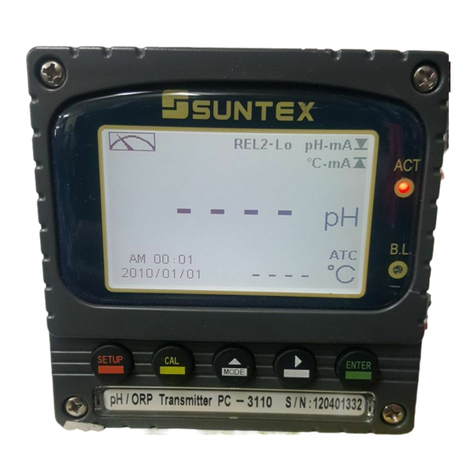
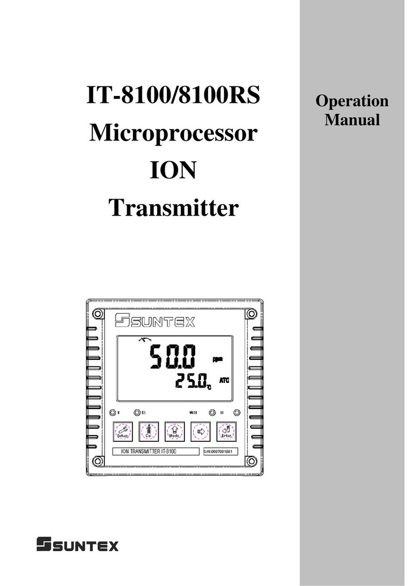
Suntex PC-300A Series User manual

PC-300A
Series
Microprocessor
pH/ORP
Transmitter
Operation
Manual

CONTENTS
Precautions for installation
1. Specifications..............................................................................................................................1
2. Assembly and installation
2.1 Transmitter installation..........................................................................................................2
2.2 Illustration of panel mounting................................................................................................2
2.3 Assembly of electrode and housing.......................................................................................3
2.3.1 Cable setup....................................................................................................................3
2.3.2 Assembly of immersive holder and junction box 8-09-5+PP-100A (Optional)...........3
2.3.3 Illustration of PP protective holder and L-shaped holder support base........................5
2.4 Illustration and description of the round junction box...........................................................6
2.5 Illustration and description of the square junction box..........................................................9
3. Wiring
3.1 Illustration of rear panel........................................................ ..............................................12
3.2 Descriptions of terminal function........................................................................................13
3.3 Wiring descriptions of transmitter............................................ ...........................................14
3.3.1 Illustration of electrical connection............................................................................14
3.3.2 Wiring of ATC probe and fixed temperature compensation.......................................15
3.4 Illustration of accessorial transmitter pH-300T (Optional)..................................................16
3.5 Connection of transmitter and accessorial transmitter pH-300T.........................................17
3.6 Wiring description of pH-300T............................................................................................18
3.7 Calibration steps after installation of pH-300T........................ ...........................................20
3.8 Illustration of online pH/ORP measurement system (Optional)..........................................21
4. Configuration
4.1 Illustration of front panel of PC-310A.................................................................................22
4.2 Illustration of front panel of PC-320A.................................................................................24
4.3 Block diagram of PC-300A.................................................................................................25
5. Calibration
5.1 Calibration of pH electrode..................................................................................................26
5.2 Inspection of ORP electrode................................................................................................27
6. Setting
6.1 RELAY control setup...........................................................................................................29
6.2 Analog output setting and RELAY test................................................................................30
7. Maintenance.............................................................................................................................32
Thank you for purchasing Suntex products. In order to improve and enhance the transmitter’s
function, Suntex reserves the right to modify the contents and icon display of the product. The actual
situation is subject to the instrument without notice. The operation manual is only provided for
function and installation description, Suntex Instruments Co., Ltd. is not liable for any person or
entity for any direct or indirect loss or damage due to improper usage of this product. If you have any
questions or find omission, negligence or mistakes in the operation manual, please contact us, thank
you.
Precautions for installation
Wrong wiring will lead to breakdown or electrical shock of the instrument, please read this operation
manual carefully prior to installation.
Make sure to remove AC power from the transmitter before wiring input, output connections, and
remove it before opening the transmitter’s housing.
The installation site of the transmitter should be good in ventilation and avoid direct sunshine.
The material of signal cable should be special coaxial cable. Strongly recommend using our coaxial
cable. Do not use normal wires instead.
Avoid electrical surge when using power. Especially when using three-phase power, use ground
wire correctly. If the power surges interference occurs, separate the power supply of transmitter
from the control device, such as: dosing machines, mixers, etc. to make individual power supply for
the transmitter; or set surge absorber to reduce the power surges at all electromagnetic switches and
power control device coils.
The internal relay contact of the instruments is for alarm or control function. Due to safety, it is a
must to connect to external relays that can withstand enough amperes, which makes sure the
safety operation of the instrument. (Please refer to ch3.3.1 Illustration of electrical control.)

1. Specification
Model PC-310A PC-320A PH-300T
Measurement modes pH/ORP
Ranges
pH 0.00~14.00 pH
ORP -1999~1999 mV
TEMP -
Resolutions
pH 0.01pH
ORP 1mV
TEMP -
Accuracy
pH ±0.01pH (±1 Digit)
ORP ±0.1% (±1 Digit)
TEMP -
Auto Temperature
Compensation NTC30K Auto Temp Comp (optional) PT1K Auto Temp Comp
(optional)
Manual Temperature
Compensation Temp Comp at 25°C/ Temp Comp. with Resistance Temp Comp. with
Resistance
Ambient Temp. 0~50°C
Storage Temp
-20~70
°
C
Input Impedance >10
12
Ω
Display LCD display with digits and function
indicators LCD display
Analog Output Isolated DC 4~20mA output, corresponding to
0~14pH or -1000~1000mV
Low resistance DC
output or DC 4~20mA
output
C
ontrol
Setting 2×RELAY 4×RELAY -
Contact 2A Max. (recommended) -
Activation Hi/Lo Hi1/Hi2/Lo1/Lo2 -
Function check Set up an analog output of 4mA or 20mA to see
if RELAY works properly -
Voltage Output DC±12V, 1W Max. for pH-300T (optional) -
Power supply 100V~240 VA C ± 1 0%, 6W Max., 50/60Hz DC 32V Max.
Installation Panel Mounting Wall or pipe mounting
Dimensions 144mm × 144mm × 195mm (H×W×D) 70mm × 110mm × 45
mm
(H×W×D)
Cut off Dimensions 135 mm × 135 mm (H×W) -
Weight 1.2Kg 0.4Kg
Note: The specifications are subject to change without notice.
1

2.Assembly and installation
2.1 Transmitter installation
Prepare a square hole of 135mm x 135mm on the panel box, and then insert the transmitter directly
into the panel box. Fit the transmitter with brackets and fasten them with screwdriver.
2.2 Illustration of panel mounting
At least 180mm
+
At least
194 mm
+
+
+
Hole distances on the panel box
135 mm
13
5 mm
Front view
Hole size
Mounting bracket
Screws
M
ounting
bracket
195 mm
Side view
2

2.3Assembly of electrode and housing
2.3.1 Cable set-up
a. Make sure to remove the conductive rubber or aluminum-foil layer between the electrode
signal wire and the coaxial shield.
b. Extend the cable to the transmitter without any joint except specific junction box. Connect
the transparent coaxial inner directly to the Glass terminal on the back of transmitter, and
metal connect coaxial shield to Ref. terminal.
2.3.2Assembly of immersive electrode holder and junction box 8-09-5+ PP-100A (Optional)
W/O a temp.
probe W/ NTC30K W/ PT1000
W/O a temp.
probe, W/ a SG
probe
PP-100A PP-100AN PP-100AP PP-100AE
Note: 1. PP-xxxA series is applied to 2-wire distribution only.
2. PP-xxxAE series is applied to 3-wire distribution only.
Set-up diagram of coaxial cable:
Follow the left set-up illustration.
The black
conductive rubber covering on the coaxial inner
should be removed.
Transparent coaxial inner (remove the conductive rubber)
Metal coaxial shield
A---- Upper cover of round junction box F---- O-ring
B---- O-ring G---- PP Electrode Protective Housing
C---- Cable fixing gland MG16A
H---- Electrode (Sensor
)
D---- Lower cover of round junction box I---- Rubber electrode holder
E---- Cable fixing point MG16A J---- PP pipe protective cover
PP protective holder:
3

1. Insert the electrode (H) through PP Electrode Protective Housing (G)
2. Rinse the electrode (H) properly so that it can be easily passed through Rubber electrode
holder (I), with about 5cm left below.
3. Install the prepared Rubber electrode holder (I) into PP Electrode Protective Holder (G) and
fix PP pipe protective cover (J) tightly.
4. Insert the Electrode cable (H) through Lower cover of round junction box (D) and Cable
fixing gland (C), and use Lower cover of round junction box (D) to fix PP Electrode
Protective Housing (G) tightly.
Note: The (F) O-shaped ring should be fixed into a glove on PP Electrode Protective Housing
(G) correctly.
5. Prepare 15cm cable in the PP pipe, and then fix Cable fixing gland MG16A(C) tightly. Leave
electrode cable (H) for about 12-14cm, and split it carefully.
6. Fix the terminal of electrode coaxial inner on terminal block 1 of round holder; Fix the
terminal of electrode coaxial shield on terminal block 3. (See the instruction of junction box)
7. Extend the cable to pass through Cable fixing gland (E) on Lower cover of round junction
box (D), and fix Cable fixing gland MG16A (E) tightly, leaving 12-14cm in the box for split.
8. Extend the lead coaxial inner and electrode coaxial inner to connect them; extend the lead
coaxial shield to fix on the terminal block 3. Tight up Upper cover of round junction box (A)
to finish the installation.
Note: The (B) O-shaped ring should be placed below the round junction box (D) correctly.
Installation of holder support base
The L-shaped electrode holder support base is installed by finding an appropriate position in
the edge of a pool according to the field’s requirements with nails or expansion screws.
A------Holder U-shaped clamp
B------Immersive holder (PP-100A)
C------Holder fixed plate
D------Support base
E------Plastic screws
8-26-7: Plastic L-Shaped Electrode Holder Support Base
7202-00416A: Stainless L Shaped Electrode Holder Support Base
4

1. Fix the holder fixed plate (C) into the L-shaped support base (D)
2. Fix the U-shaped clamp (A) into immersive holder (B)
3. Combine abovementioned items together by screwing them up with plastic screws (E)
2.3.3 Illustration of PPprotective holder and L-shaped holder support base
58.5mm
28mm
56mm
56mm
∅7mm
8-26-7: Plastic L-Shaped Electrode
Holder Support Base
Plastic material: PP
Max. resistance temperature: 80°C
50mm
40mm
110mm
1160mm
(PP
-100A)
5

2.4 Illustration and description of the round junction box
i. 2-wire distributing system:
i. Two-wire distributing system
Labels on round junction box
Terminals on transmitter
INPUT terminals Terminal
No.
OUTPUT terminals
(7202-RG-58)
(7202-F94009-BK)
Coaxial inner from sensor 1 Coaxial inner GLASS
Shield (forbidden) 2 Shield (forbidden) ------
Coaxial shield from sensor 3 Coaxial shield REF
Green wire from temp. probe 4 Green wire SG
Red wire from temp. probe 5 Red wire AT C
Alternative 6, 7 Alternative ------
(8-09-5)
Note: It is necessary to make REF and SG
short-circuited as 2-wire distribution
system is applied (with a built-in
jumper between them).
w/o a temp. probe
Use coaxial shield wire 7202-RG-58
w/ a temp. probe
Use coaxial 4-core wire 7202-F94009-BK
Junction box
Temp. probe
Transparent
Shield
IN
OUT
Green
Red
pH/ORP
sensor
Transparent
Transparent
Shield
Shield
Gr
G
r
Red
Red
Black
6

Note: 1. Extension cable; Order Number: 7202-F94009-BK or 7202-RG-58
(1) Select RG-58 if temperature probe is not used. (Order No.: 7202-RG-58)
(2) Select F94009-BK if temperature probe is used. (Order No.: 7202-F94009-BK)
2. As temperature probe 8-26-3 (NTC30K) or 8-26-8 (PT1K) is used for two-wire
distribution, the black wire should be forbidden.
ii. 3-wire distributing system:
(8-09-5)
Junction box
pH/ORP
sensor
Temp. probe
Coaxial 4
-core wire: 7202-F94009-BK
OUT
IN
Transparent
Transparent
Transparent
Green
Gr
Gr
Red
Shield
Red
Shield
Shield
Red
Black
N
ote:
The SG probe is connected to terminal 2 as it is
used instead of a temp. probe.
A
t the time, red wire
from 7202
-F94009-BK is NC.
Note:
The jumper between REF and
SG should be removed as 3-wire
distribution system is applied.
7

ii. Three-wire distributing system
Labels on round junction box Terminals on transmitter
IN terminals T
erminal
No.
OUT terminals
(7202-F94009-BK)
Coaxial inner from sensor 1 Coaxial inner GLASS
Green wire from temp. probe + black
wire from temp. probe (SG probe) 2 Coaxial shield SG
Coaxial shield from sensor 3 Green wire REF
Red wire from temp. probe 4 Red wire AT C
Alternative 5, 6, 7 Alternative ----
Note: 1. The black wire from temperature probe 8-26-3 (NTC30K) or 8-26-8 (PT1K) is used as
SG and it is connected together with the green wire to terminal 2 on junction box.
2. It is necessary to apply our coaxial 4-core wire: 7202-F94009-BK that contains
temperature and solution ground.
8

2.5 Illustration and description of the square junction box
i. 2-wire distributing system:
i. Two-wire distributing system
Labels on square junction box
Terminals on transmitter
INPUT terminals Terminal No.
OUTPUT terminals
(7202-RG-58)
(7202-F94009-BK)
Coaxial inner from sensor GLASS (1) Coaxial inner GLASS
Coaxial shield from sensor REF (2) Coaxial shield REF
Green wire from temp. probe SG (3) Green wire SG
Red wire from temp. probe TP (4) Red wire AT C
Alternative NC (0, 5, 6, 7)
Alternative ------
Note: It is necessary to make REF and SG
short-circuited as 2-wire distribution
system is applied (with a built-in
jumper between them).
w/o a temp. probe
Use coaxial shield wire 7202-RG-58
w/ a temp. probe
Use coaxial 4-core wire 7202-F94009-BK
(8-09)
IN OUT
Square junction box
pH/ORP
sensor
T
emp.
probe
Transparent
Transparent Transparent
Shield
Shield
Shield
Green
Green Green
Red
Red Red
Black (NC)
IN OUT
9

Note: 1. Extension cable; Order Number: 7202-F94009-BK or 7202-RG-58
(1) Select RG-58 if temperature probe is not used. (Order No.: 7202-RG-58)
(2) Select F94009-BK if temperature probe is used. (Order No.: 7202-F94009-BK)
2. As temperature probe 8-26-3 (NTC30K) or 8-26-8 (PT1K) is used for two-wire
distribution, the black wire should be forbidden.
ii. 3-wire distributing system:
Note:
The jumper between REF and
SG should be removed as 3-wire
distribution system is applied.
S
quare junction box
Coaxial 4
-core wire
:
7202
-
F94009
-
BK
pH/ORP
sensor
T
emp.
probe
IN OUT
Shield
Shield Green
Shield
Green
Gr
Transparent
Transparent
Transparent
Red
Red
BL
Red
10

ii. Three-wire distributing system
Labels on round junction box
Terminals on transmitter
IN terminals Terminal No. OUT terminals
(7202-F94009-BK)
Coaxial inner from sensor GLASS (1) Coaxial inner GLASS
Coaxial shield from sensor REF (2) Coaxial shield REF
Green wire from temp. probe + black
wire from temp. probe (SG probe) SG (3) Green wire SG
Red wire from temp. probe TP (4) Red wire AT C
Alternative NC (0, 5, 6, 7)
Alternative ------
Note: 1. The black wire from temperature probe 8-26-3 (NTC30K) or 8-26-8 (PT1K) is used as
SG and it is connected together with the green wire to SG terminal on the junction box.
2. It is necessary to apply our coaxial 4-core wire: 7202-F94009-BK that contains
temperature and solution ground.
11

3. Wiring
3.1 Illustration of rear panel
Note 2: Put the pH or ORP sticker once measurement mode is selected for convenience of
recognition.
Note 1:
Unused cable glands
should be plugged with
rubber plugs.
12

3.2 Descriptions of terminal function
GLASS
Connecting to the coaxial inner
(transparent wire) of pH/ORP electrode
signal wire
REF Connecting to the coaxial shield (net wire)
of pH/ORP electrode signal wire
SG
1. SG and REF should be short circuited
with a jumper if two-wire system is
used. (There is a jumper after out of
factory.)
2. Remove the jumper if three-wire system
is used. It should connect one end of
solution ground or temperature probe.
ATC Connect the other end of temperature
probe
1. If ATC probe or resistance is not used,
terminals of MTC should be
short-circuited by a jumper, which is
regarded as compensation at 25°C (with
a built-in jumper between them).
2. If ATC probe or resistance is used, a
jumper should be removed.
Transfer a jumper from terminals of MTC
to ORP as it goes to ORP measurement.
DC ± 12V DC output terminal ±12V
(for our PH-300T only)
SG Ground terminal of DC output ±12V
Isolated current output terminals for
external recorders or PC:
4~20mA matched to 0~14 pH
4~20mA matched to -1000~1000 mV
Terminals for power supply
(100~240VAC)
Terminals for relay control
(H1 or L1)
Terminals for relay control
(H2 or L2) <PC-320A Only>
Ground terminal for power supply
SG
REF
SG
-
12V
+
12V
GLASS
ORP
+
OUTPUT
4~20mA
-
MTC
ATC
3 Wires
2 Wires
MTC
POWER(L)
POWER(N)
COM
NC
NO
L2
H2
L1
COM
NO
COM
NO
POWER(L)
POWER(N)
H1
COM
NC
NO
E
ORP
OUTPUT
4~20mA
+
-
NC
COM
NO
COM
NO
E
13

3.3 Wiring descriptions of transmitter
3.3.1 Illustration of electrical connection
Note: Repair and replacement of the built-in miniature relay of transmitter require professional
technicians. It is recommended to connect an external relay (Power Relay) with our
transmitters to activate surrounding equipments.
E
COM
NO
Transmitter
100~240 VA C
Relay L1
Relay H2
Relay L2
100~240
VAC
Relay H1
COM
NO
NC
NC
COM
NO
COM
NO
COM
NO
Dosing pump
Surge absorber
M
Dosing pump
Surge absorber
M
Dosing pump
Surge absorber
M
Dosing pump
Surge absorber
M
Surge absorber
External relay
Surge absorber
External relay
Surge absorber
External relay
Surge absorber
External relay
14

MTC
ATC
SG
3.3.2 Wiring of ATC probe and fixed temperature compensation
R value for fixed temperature compensation (PC-310A/PC-320A)
Temp. 0°C 5°C 10°C 15°C 20°C 25°C
R value 94.98K 74.44K 58.75K 46.67K 37.30K 30.00K
Temp. 30
°
C 35
°
C 40
°
C 45
°
C 50
°
C 55
°
C
R value 24.27K 19.74K 16.15K 13.28K 10.97K 9.109K
Temp. 60°C 65°C 70°C 80°C 90°C 100°C
R value 7.599K 6.367K 5.359K 3.843K 2.799K 2.069K
PC-350A
Temp. 0
°
C 5
°
C 10
°
C 15
°
C 20
°
C
R value 1000Ω 1019.25Ω 1038.5Ω 1057.75Ω 1077Ω
Temp. 25
°
C 30
°
C 35
°
C 40
°
C 45
°
C
R value
1096.25Ω 1115.5Ω 1134.75Ω 1154Ω 1173.25Ω
Temp. 50
°
C 55
°
C 60
°
C 65
°
C 70
°
C
R value 1192.5Ω 1211.75Ω 1231Ω 1250.25Ω 1269.5Ω
Temp. 75
°
C 80
°
C 85
°
C 90
°
C 100
°
C
R value 1288.75Ω 1308Ω 1327.25Ω 1346.5Ω 1385Ω
Note: Remove the jumper from terminals on MTC if a temperature probe is used or
temperature compensation with resistance is used.
To solution
ground
AT C
ToATC probe
T
oATC probe
MTC
ATC
SG R
Temperature compensation
with resistance
(PC-310A/PC-320A/PC-350A)
Temperature compensation
at 25°C (PC-310A/PC-320A)
MTC (PC-350A)
With a jumper
MTC
ATC
SG
15

3.4 Installation of accessorial transmitter PH-300T (Optional)
Accessorial pH/ORP transmitter, PH-300T, is mainly installed on the electrode protective pipe,
but it also can be applied to wall mounting or pipe mounting. For long distance transmission
(100m), for example, if the distance between a transmitter and an electrode overweighs 30
meter long, it is recommended that accessorial transmitter PH-300T should be used to avoid
the attenuation of electrode signal which also leads to convenience of onsite observation,
measurement, and calibration.
Illustration of wall mounting type
1. Combine the sun shield and PH-300T transmitter by round stainless steel screws 4x15
2. Fix item 1 combination on wall by self-tapping screws
Illustration of pipe mounting type
1. Fix immersive holder (B) into U-shaped clamp (A)
2. Combine the item 1. combination with PH-300T (C) by Round stainless steel screws 4×15
A------Sun shield of PH-300T
B------PH-300T transmitter
C------Round stainless steel screws 4x15
D------Self-tapping screws (defined by customer)
A------U-shaped clamp
B------Immersive holder
C------PH-300T transmitter
D------Round stainless steel screws 4×15
16

3.5 Connection of transmitter and accessorial transmitter PH-300T
A. Connect the GLASS point of transmitter PH-300T’s terminal to the electrode coaxial inner.
(Note: Remove the black conductive rubber); connect the REF point of transmitter PH-300T’s
terminal to the electrode coaxial shield.
B. Regarding two-wire distributing system and three-wire distributing system please refer to ch3.6.
C. Sign “PT-1000” on transmitter PH-300T’s terminal is the connector for automatic temperature
compensation probe, PT-1000, or applies a fixed temperature compensation resistance.
D. The V+ and V- of transmitter PH-300T’s terminal respectively connect to DC12V+ and – of the
transmitter.
E. The S+ and S- on transmitter PH-300T’s terminal respectively connect to GLASS and REF of
the transmitter.
F. The I+ and I- on transmitter PH-300T’s terminal are output (4-20mA), which can connect to
devices that receive current signals.
Note:
1. Do not share the same power supply with more transmitters at a time under 2-wire
distributing system.
2.As the current output signal of transmitter is not insulated, it is unavailable to connect
with PC or PLC; or it would do damage on electrodes.)
Refer to the following table for proper fixed temperature compensation resistance
Temperature
0
°
C
5
°
C
10
°
C
15
°
C
20
°
C
R value 1000Ω 1019.25Ω 1038.5Ω 1057.75Ω 1077Ω
Temperature
25
°
C
30
°
C
35
°
C
40
°
C
45
°
C
R value 1096.25Ω 1115.5Ω 1134.75Ω 1154Ω 1173.25Ω
Temperature
50
°
C
55
°
C
60
°
C
65
°
C
70
°
C
R value 1192.5Ω 1211.75Ω 1231Ω 1250.25Ω 1269.5Ω
Temperature
75
°
C
80
°
C
85
°
C
90
°
C
100
°
C
R value 1288.75Ω 1308Ω 1327.25Ω 1346.5Ω 1385Ω
17
Table of contents
Other Suntex Transmitter manuals

Suntex
Suntex EC-4110 User manual

Suntex
Suntex TC-7310-RS-M User manual

Suntex
Suntex TC-7100 User manual

Suntex
Suntex CT-6110-POL User manual

Suntex
Suntex EC-4110-I User manual

Suntex
Suntex PC-3110-RS User manual

Suntex
Suntex TC-7310-RS User manual

Suntex
Suntex PC-3310-RS User manual

Suntex
Suntex CT-6300RS User manual

Suntex
Suntex PC-3110-P User manual