manuals.online logo
Brands
  1. Home
  2. •
  3. Brands
  4. •
  5. teko
  6. •
  7. Security Sensor
  8. •
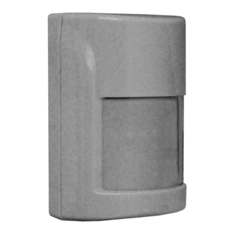
  9. teko Astra-551 User manual

teko Astra-551 User manual

Other teko Security Sensor manuals

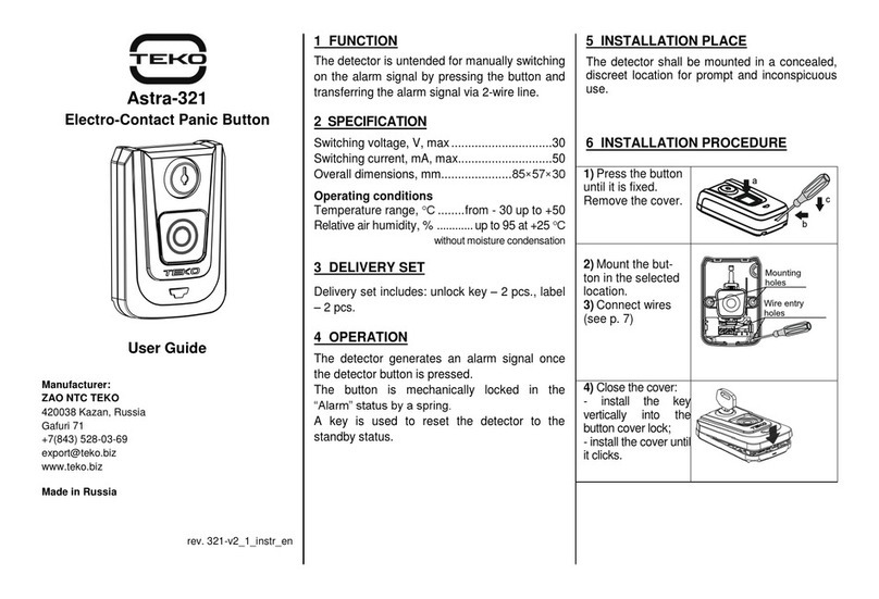
teko Astra-531 DC Installation instructions

teko

teko Astra-531 DC Installation instructions

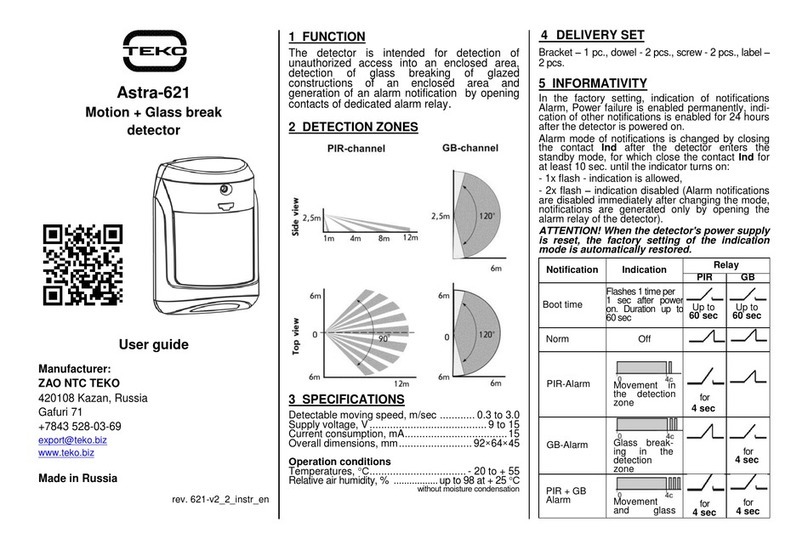
teko Astra-621 RF User manual

teko

teko Astra-621 RF User manual

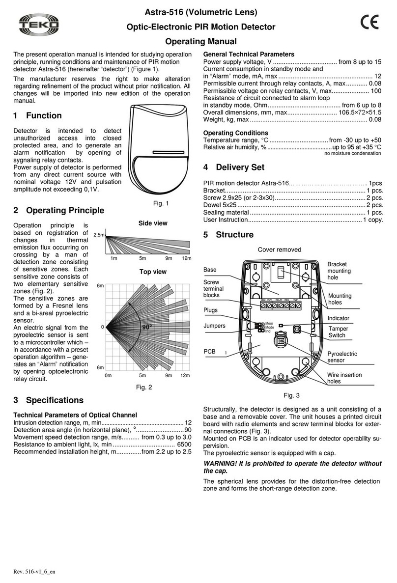
teko Astra-516 User manual

teko

teko Astra-516 User manual

teko Astra-5131 User manual

teko

teko Astra-5131 User manual

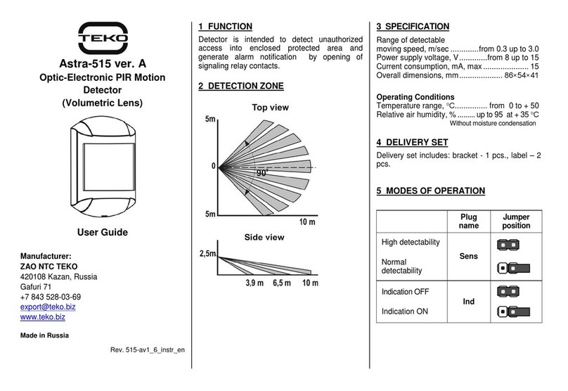
teko Astra-515 ver.A User manual

teko

teko Astra-515 ver.A User manual

teko Astra-531 PIR Installation instructions

teko

teko Astra-531 PIR Installation instructions

teko Astra-531 AC Installation instructions

teko

teko Astra-531 AC Installation instructions

teko Astra-7 ver.A User manual

teko

teko Astra-7 ver.A User manual

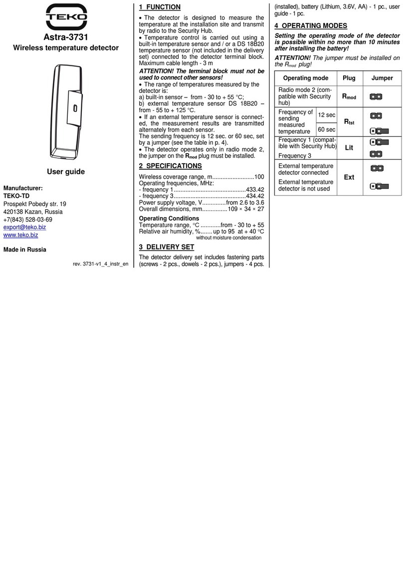
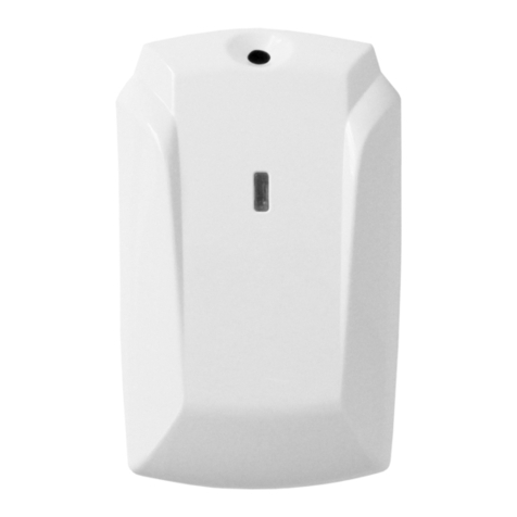
teko Astra-GB User manual

teko

teko Astra-GB User manual

teko Astra-GB Installation instructions

teko

teko Astra-GB Installation instructions

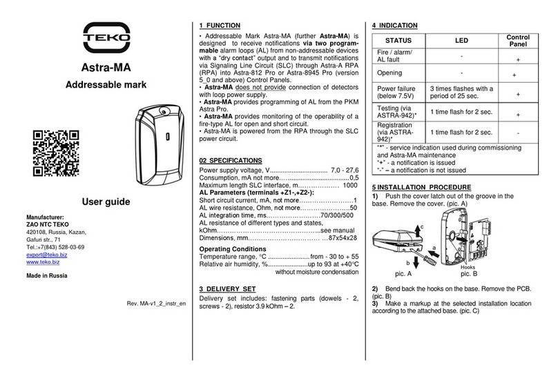
teko Astra-MA User manual

teko

teko Astra-MA User manual

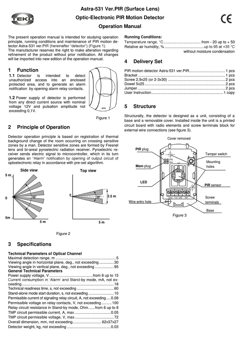
teko Astra-531 Ver.PIR User manual

teko

teko Astra-531 Ver.PIR User manual

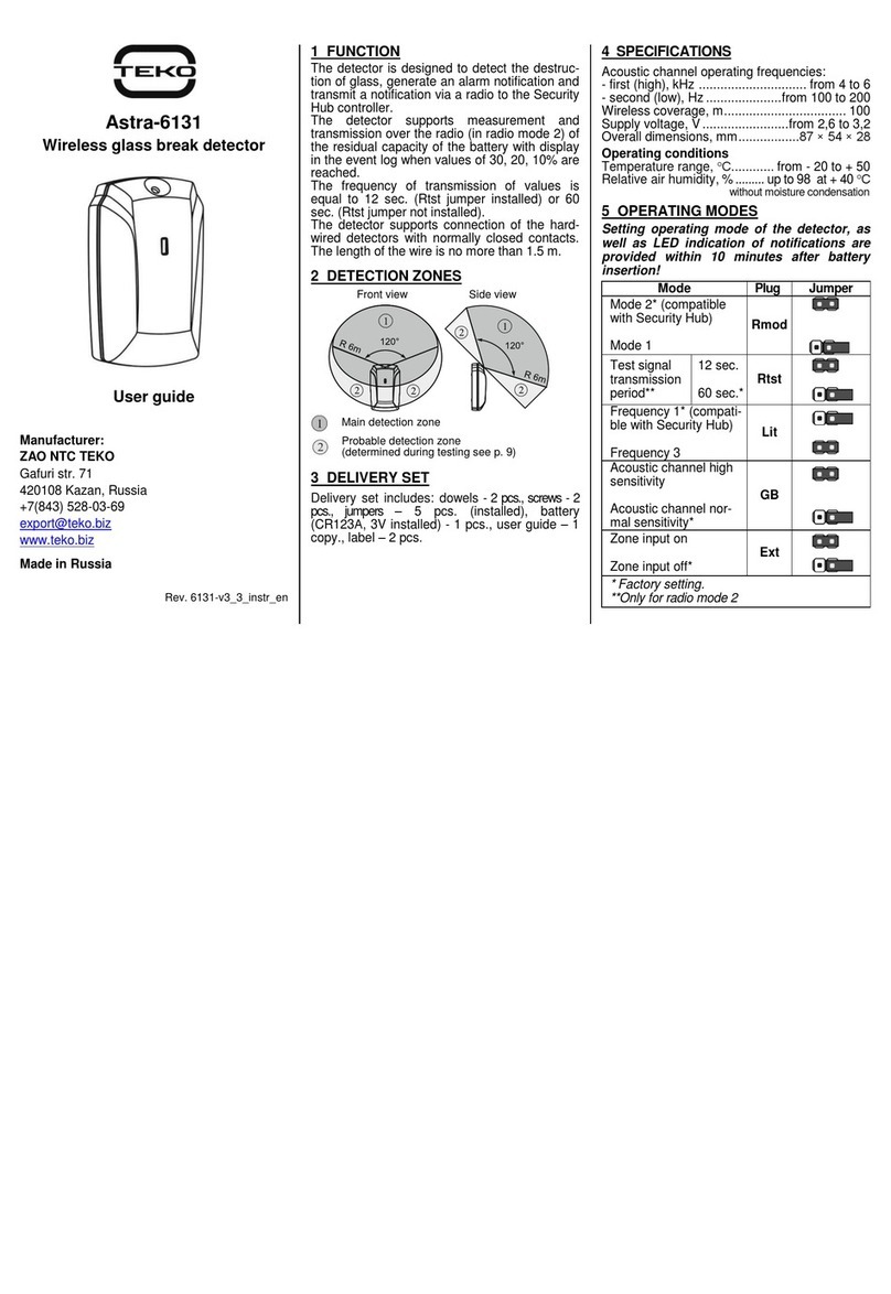
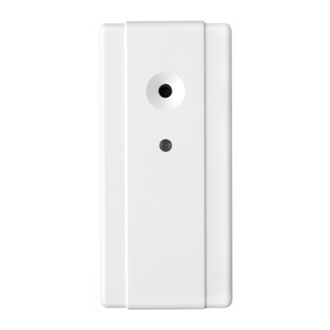
teko Astra-6131 User manual

teko

teko Astra-6131 User manual

teko Astra-361 Installation instructions

teko

teko Astra-361 Installation instructions

teko Astra-621 User manual

teko

teko Astra-621 User manual

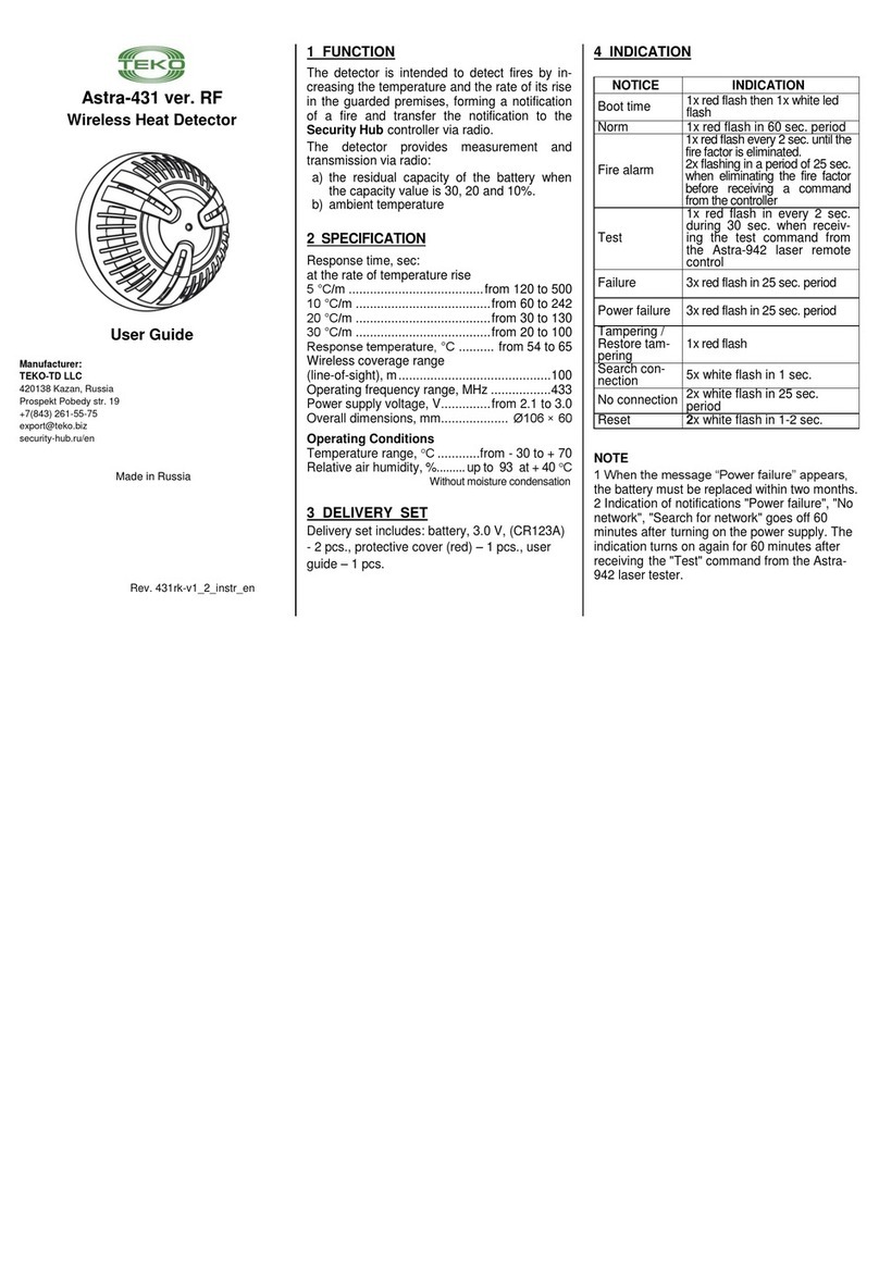
teko Astra-431 User manual

teko

teko Astra-431 User manual

teko Astra-621 User manual

teko

teko Astra-621 User manual

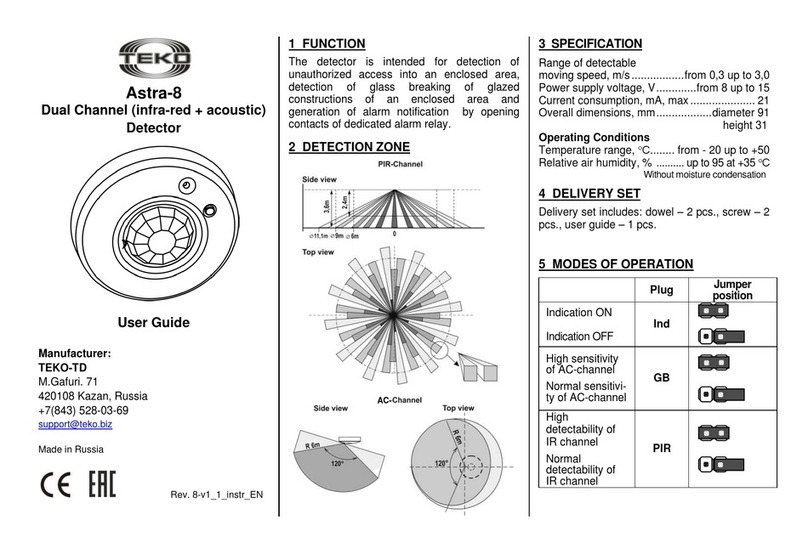
teko Astra-8 User manual

teko

teko Astra-8 User manual

teko Astra-621 User manual

teko

teko Astra-621 User manual

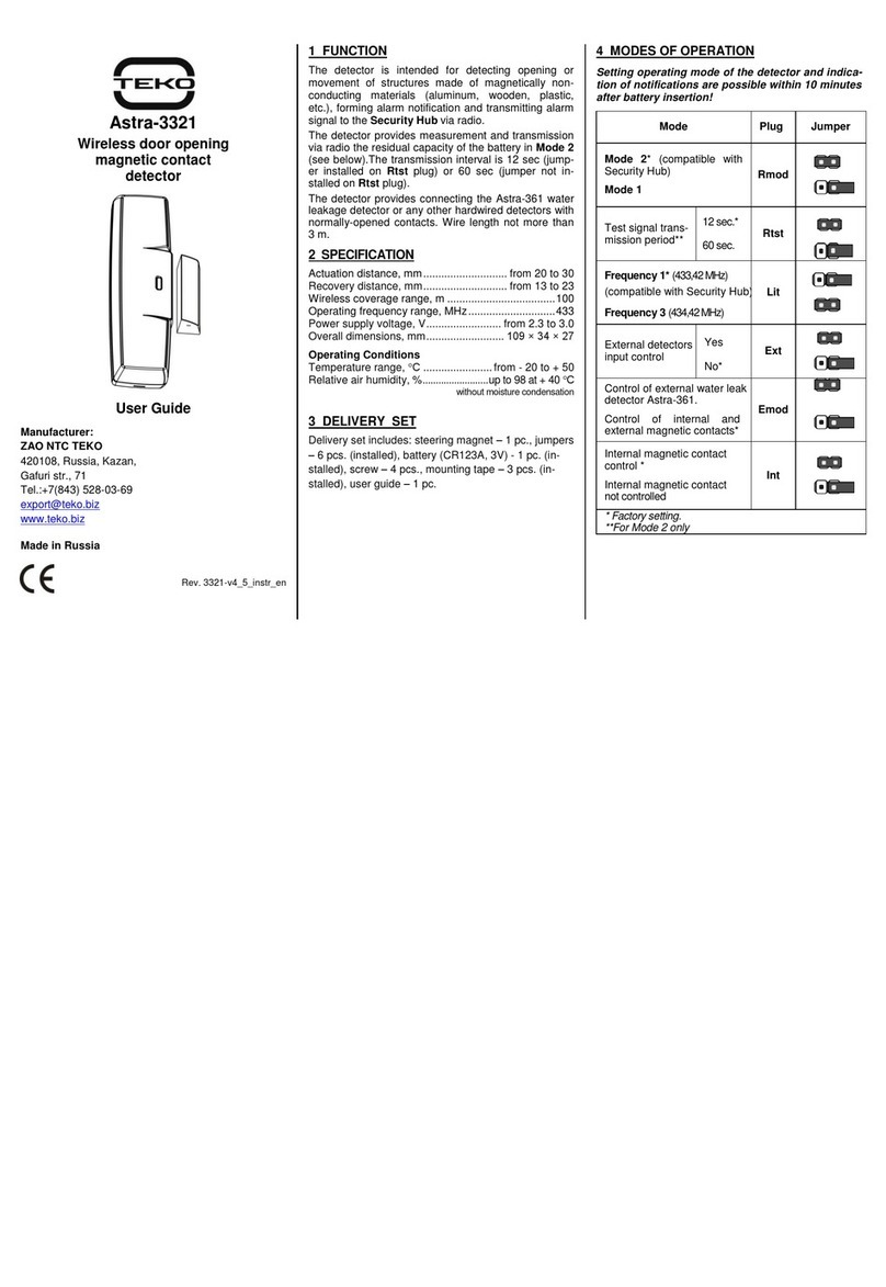
teko Astra-3221 User manual

teko

teko Astra-3221 User manual

teko Astra-5121 User manual

teko

teko Astra-5121 User manual

teko Astra-9 User manual

teko

teko Astra-9 User manual

teko Astra-642 User manual

teko

teko Astra-642 User manual

teko Astra-A ILS User manual

teko

teko Astra-A ILS User manual

Popular Security Sensor manuals by other brands

Honeywell Home PROSiXCOCN Installation and setup guide

Honeywell Home

Honeywell Home PROSiXCOCN Installation and setup guide

Duevi SIRPZ-RB-868 Operation

Duevi

Duevi SIRPZ-RB-868 Operation

RKI 65-2483RK Operator's manual

RKI

RKI 65-2483RK Operator's manual

Nortech PD160 Enhanced Series user manual

Nortech

Nortech PD160 Enhanced Series user manual

Omron K8AC-H2 manual

Omron

Omron K8AC-H2 manual

Agilent Technologies G8610 Series Quick reference card

Agilent Technologies

Agilent Technologies G8610 Series Quick reference card

Shinko SE2EA-1-0-0 instruction manual

Shinko

Shinko SE2EA-1-0-0 instruction manual

Det-Tronics X Series instructions

Det-Tronics

Det-Tronics X Series instructions

ACR Electronics COBHAM RCL-300A Product support manual

ACR Electronics

ACR Electronics COBHAM RCL-300A Product support manual

TOOLCRAFT 1712612 operating instructions

TOOLCRAFT

TOOLCRAFT 1712612 operating instructions

Elkron IM600 Installation, programming and functions manual

Elkron

Elkron IM600 Installation, programming and functions manual

Bosch WEU PDO 6 Original instructions

Bosch

Bosch WEU PDO 6 Original instructions

THORLABS PDA10JT user guide

THORLABS

THORLABS PDA10JT user guide

Waeco UV-DETECT operating manual

Waeco

Waeco UV-DETECT operating manual

Intermatic IOS-DSIMF manual

Intermatic

Intermatic IOS-DSIMF manual

Siemens AZL66 Series manual

Siemens

Siemens AZL66 Series manual

BTI Profiline Multi Finder operating instructions

BTI

BTI Profiline Multi Finder operating instructions

Challenger SL01 instruction manual

Challenger

Challenger SL01 instruction manual

manuals.online logo
manuals.online logoBrands
  • About & Mission
  • Contact us
  • Privacy Policy
  • Terms and Conditions

Copyright 2025 Manuals.Online. All Rights Reserved.

Astra-551
Combined Volumetric
Detector
(PIR + Microwave)
User Guide
Manufacturer:
TEKO-TD LLC
420138 Kazan, Russia
Prospekt Pobedy str. 19
+7(843) 528-03-69
[email protected]
Made in Russia
Rev. 551-v1_4_instr_EN
1 FUNCTION
The detector is intended for detection of
unauthorized access into an enclosed area, and
generation of an alarm notification by opening
contacts of dedicated signaling relay if signals
are present in both detection channels - infrared
and microwave (PIR and MW).
2 DETECTION ZONE
3 SPECIFICATION
Range of detected
moving speed, m/sec .................from 0.3 to 3.0
Power supply voltage, V..................from 8 to 15
Current consumption, mA, max......................16
Overall dimensions, mm.............106.5×72×51.5
Operating Conditions
Temperature range, °С............from - 30 to + 50
Relative air humidity, %..........up to 95 at + 35 °С
Withoutmoisture condensation
4 DELIVERY SET
Delivery set includes: ball bracket –1 pcs.,
dowel –2 pcs., screw –2 pcs., user guide –1
pcs.
5 OPERATING MODE
Operating mode
Plug
name
Jumper
position
Frequency shift
ON
Frequency shift
OFF
Freq
“Alarm memory”
ON
“Alarm memory”
OFF
Mem
High detectability
Normal detecta-
bility
Mode
Indication ON
Indication OFF
Ind
MW-channel
test
Mem
Seesec.9
PIR-channel
test
Ind
Seesec.9
6 SELECTING INSTALLATION PLACE
1) Recommended installation height is 2.2-2.5 m.
2) Install detector on bearing walls and carri-
ers.
3) Alarm loop and power supply wires should
be located far from power cables.
To eliminate false alarm hazards
1) It is recommended to close all doors, air-
vents, switch off fans, air-conditioners and other
sources of intense air flows in the room during
protection period.
2) It is not recommended to operate the detec-
tor in a room with high level of microwave inter-
ference (electro-magnetic signals, vibrating
metallic objects, sources of movement behind
thin partitions).
Not recommended installation place
7 INSTALLATION PROCEDURE
1) Remove cover
2) Remove PCB
3a) Installation on the wall
3b)Installation in the corner
Detector`s base should be positioned
strictly as per figure!
3c) Installation using
bracket
4) Replace PCB and
perform wiring (see
sec.8).
5) perform testing of
MW-channel and PIR-
channel (see sec.9).
8 WIRING
Perform wiring to detector`s terminals in
accordance with control panel operating manual.
TMP –detector tampering control terminals;
RES –terminating resistor connection terminal;
RELAY –terminals for detector connection to
alarm loop (zone);
GND, +12V –power supply terminals.
9 TEST
MW - channel:
1) Install jumpers on Ind and Mode plugs.
Remove jumper from Mem
plug.
2) Power detector ON.
Red and blue indicators
shall alternatively blink for
not more than 60 sec.
3) During this time
4) Assemble the detector.
5) To detect sensitive zones carry out TEST-
pass in the secured zone with the speed of 1
m/sec. Stop upon detection (indicator is lighted
red twice for 0.25sec), mark position, then
make a step back and continue moving
forward.
Repeat TEST-pass inversely.
PIR- channel:
1) Install jumpers on Ind and Mode plugs.
Remove jumper from Mem plug.
2) Power detector ON. Red and blue indicators
shall alternatively blink for not more than 60
sec.
3) During this time
4) Assemble the detector.
5) To detect sensitive zones
carry out TEST-pass in the
secured zone with the speed
of 0,3 and 3 m/sec.
Stop upon detection
(indicator lights up for 2sec),
mark position, then make a
step back and continue
moving forward.
Repeat TEST-pass inversely.
10 WARRANTY
The operation warranty period is 5 years from
the date of operation start-up but no longer than
5 years 6 months from the date of manufactur-
ing subject to the requirements of Operating
Manual.