manuals.online logo
Brands
  1. Home
  2. •
  3. Brands
  4. •
  5. superbrightleds
  6. •
  7. Controllers
  8. •
  9. superbrightleds DMX-1CH-10A User manual

superbrightleds DMX-1CH-10A User manual

Important: Read all instructions prior to installation.
DMX Master/Decoder for LED DMX Controllers
with Digital Address Display - 1 Channel, 10A
One channel DMX Controller/Decoder controls a single LED product
such as a light bar or strip. The DMX base address is easily set using
push button switches under the display. DMX-512 digital control signals
are received via 3 wire terminal strip connection. DMX decoding driver
converts universal DMX512/1990 digital signal to PWM signal, which
can be controlled by DMX512 console. 4096 grey scales are available
when used in master mode. Maximum load 10 Amps available DMX
Starting Channels 001-512.
Instructional Sheet
Part Number:
4400 Earth City Expy, St. Louis MO 63045 866-590-3533 [email protected]
Technical Specs
Product Dimension
Operation Interface Instruction
DMX-1CH-10A
Decode Channel 1CH
Input Signal DMX-512/1990 digital signal
Output Signal Constant Voltage PWM
Power Supply DC 12~24V
Power Dis. 1CH×10A
Power Output 120W(12V)/240W(24V)
Operating Temp. -30˚C~55˚C
Size L7''×W1.8''×H1.2''in (L176xW46xH30mm)
Weight 6oz (170g)
6.4in (162mm)
7in (176mm)
0.3in
(7mm)
0.3in
(7mm)
1.8in
(46mm)
0.9in
(22mm)
1.2in
(30mm)
M
-
+
+
-
GND
DMX+
DMX
-
GND
DMX+
LED DMX & PWM
DIMMER - MONO
DMX
-
OUTPUT LED
max. 1x10A
POWER IN
12-24VDC
M
-
+
+
-
GND
DMX+
DMX
-
GND
DMX+
LED DMX & PWM
DIMMER - MONO
DMX
-
OUTPUT LED
max. 1x10A
POWER IN
12-24VDC
POWER SUPPLY
M
-
+
+
-
GND
DMX+
DMX
-
GND
DMX+
LED DMX & PWM
DIMMER - MONO
DMX
-
OUTPUT LED
max. 1x10A
POWER IN
12-24VDC
POWER SUPPLY
M
-
+
+
-
GND
DMX+
DMX
-
GND
DMX+
LED DMX & PWM
DIMMER - MONO
DMX
-
OUTPUT LED
max. 1x10A
POWER IN
12-24VDC
POWER SUPPLY
DMX + DMX Data High
DMX - DMX Data Low
GND DMX Ground
DMX Input Signal (DMX 512)
DMX + DMX Data High
DMX - DMX Data Low
GND DMX Ground
DMX Output Signal
V- DC Power In Negative
V+ DC Power In Positive
DC 12-24V (12 volt - 24 volt DC)
V- DC Power Output Negative
V+ DC Power Output Positive
Output Channels (1x10 Amp - 10 Amp Total)
Display Current Starting DMX Channel
Button M Changes Digit Selection
Button + Increase Selection
Button - Decrease Selection
Display and Buttons
Wiring
Programming
Setting the base channel:
Press any button to wake up the display if no numbers are displayed. Press and hold M button for 3 seconds until hundreds digit ashes. Use + and - buttons to select hundreds
digit. Press M button until tens digit ashes. Use + and - buttons to select tens digit. Press M button until ones ashes. Use + and - buttons to select ones digit. When the desired
base channel is displayed, do not press any buttons. In approximately 15 seconds, all of the digits in the display will stop ashing and the base channel is set.
6.4in (162mm)
7in (176mm)
0.3in
(7mm)
0.3in
(7mm)
1.8in
(46mm)
0.9in
(22mm)
1.2in
(30mm)
M
-
+
+
-
GND
DMX+
DMX
-
GND
DMX+
LED DMX & PWM
DIMMER - MONO
DMX
-
OUTPUT LED
max. 1x10A
POWER IN
12-24VDC
M
-
+
+
-
GND
DMX+
DMX
-
GND
DMX+
LED DMX & PWM
DIMMER - MONO
DMX
-
OUTPUT LED
max. 1x10A
POWER IN
12-24VDC
POWER SUPPLY
M
-
+
+
-
GND
DMX+
DMX
-
GND
DMX+
LED DMX & PWM
DIMMER - MONO
DMX
-
OUTPUT LED
max. 1x10A
POWER IN
12-24VDC
POWER SUPPLY
M
-
+
+
-
GND
DMX+
DMX
-
GND
DMX+
LED DMX & PWM
DIMMER - MONO
DMX
-
OUTPUT LED
max. 1x10A
POWER IN
12-24VDC
POWER SUPPLY
DMX master mode preset patterns list:
700-999, The rst two digits indicate the mode, the third digit indicates
the speed. 10 speed levels, from 0-9. Total 31 modes, such as:
Speed for Program 700-799 and 900-999 (for one step and not for the
whole program): 0=0.5 sec. | 1=1 sec. | 2=2 sec. | 3=5 sec. | 4=10 sec. |
5=15 sec. | 6=20 sec. | 7=30 sec. | 8=60 sec. | 9=90 sec.
Speed for Program 800-899 (for one step and not for the whole pro-
gram): 0=0.02 sec. | 1=0.04 sec. | 2=0.1 sec. | 3=0.2 sec. | 4=0.5 sec. |
5=1 sec. | 6=1.5 sec. | 7=2.5 sec. | 8=5 sec. | 9=7.5 sec.
4400 Earth City Expy, St. Louis MO 63045 866-590-3533 [email protected]
Warranty Agreement
1. A Lifetime Warranty is given from the date of purchase. The warranty
is for free repair or replacement and covers manufacturing faults only.
2. Warranty exclusions:
•Any damages caused from improper operation,or connecting to
excess voltage and overloading.
•The product appears to have excessive physical damage.
•Damage due to natural disasters and accidents.
3. Repair or replacement as provided under this warranty is the
exclusive remedy to the customer. We shall not be liable for any
incidental or consequential damages for breach of any stipulation in
this warranty.
4. Any amendment or adjustment to this warranty must be approved
in writing by our company only.
Conjunction Diagram Operation Instructions
1. The product shall be installed and serviced by a qualied person.
2. This product is non-waterproof. Please avoid the sun and rain. When installed
outdoors, please ensure it is mounted in a waterproof enclosure.
3. Good heat dissipation will prolong the working life of the controller. Please
ensure good ventilation.
4. Make sure if the output voltage of any LED power supplies used complies with
the working voltage of the product.
5. Ensure that adequate-sized cable is used from the controller to the LED lights to
carry the current. Also ensure that the cable is secured tightly in the connector
to avoid the accidents due to overheat and poor contact on the wire.
6. Ensure all wire connections and polarities are correct before applying power to
avoid any damages to the LED lights.
7. If a fault occurs please return the product to your supplier. Do not attempt to x
this product by yourself.
Safety & Warnings
Screen Indicators
DMX Application
Master
DMX
Console
Controller
Slave
Slave
000 100% brightness 840-849 Strobe with jumping from 15-100%
600-699 Dimming,0%-99% 850-859 Strobe with jumping from 20-100%
700-709 Fading from 0-100% 860-869 Strobe with jumping from 30-100%
710-719 Fading from 1-100% 870-879 Strobe with jumping from 40-100%
720-729 Fading from 5-100% 880-889 Strobe with jumping from 50-100%
730-739 Fading from 10-100% 890-899 Strobe with jumping from 60-100%
740-749 Fading from 15-100% 900-909 Fade up from 0% to 100% then jump to 0%
750-759 Fading from 20-100% 910-919 Fade up from 1% to 100% then jump to 1%
760-769 Fading from 30-100% 920-929 Fade up from 5% to 100% then jump to 5%
770-779 Fading from 40-100% 930-939 Fade up from 10% to 100% then jump to 10%
780-789 Fading from 50-100% 940-949 Fade up from 15% to 100% then jump to 15%
790-799 Fading from 60-100% 950-959 Fade up from 20% to 100% then jump to 20%
800-809 Strobe with jumping from 0-100% 960-969 Fade up from 30% to 100% then jump to 30%
810-819 Strobe with jumping from 1-100% 970-979 Fade up from 40% to 100% then jump to 40%
820-829 Strobe with jumping from 5-100% 980-989 Fade up from 50% to 100% then jump to 50%
830-839 Strobe with jumping from 10-100% 990-999 Fade up from 60% to 100% then jump to 60%
70=Fading form 0-100%
Mode
Level 4=10 sec.
Speed
The decimal point of the last digit of the display will blink regularly when receiving
a DMX512 signal. When no signal is received, the decimal point does not ash,
and the display shows the current DMX address. After approximately one minute
the screen saver turns off the display. Press any key to activate the display.
6.4in (162mm)
7in (176mm)
0.3in
(7mm)
0.3in
(7mm)
1.8in
(46mm)
0.9in
(22mm)
1.2in
(30mm)
M
-
+
+
-
GND
DMX+
DMX
-
GND
DMX+
LED DMX & PWM
DIMMER - MONO
DMX
-
OUTPUT LED
max. 1x10A
POWER IN
12-24VDC
M
-
+
+
-
GND
DMX+
DMX
-
GND
DMX+
LED DMX & PWM
DIMMER - MONO
DMX
-
OUTPUT LED
max. 1x10A
POWER IN
12-24VDC
POWER SUPPLY
M
-
+
+
-
GND
DMX+
DMX
-
GND
DMX+
LED DMX & PWM
DIMMER - MONO
DMX
-
OUTPUT LED
max. 1x10A
POWER IN
12-24VDC
POWER SUPPLY
M
-
+
+
-
GND
DMX+
DMX
-
GND
DMX+
LED DMX & PWM
DIMMER - MONO
DMX
-
OUTPUT LED
max. 1x10A
POWER IN
12-24VDC
POWER SUPPLY

Other superbrightleds Controllers manuals

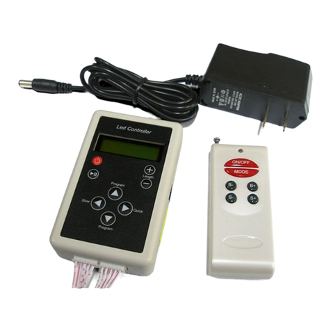
superbrightleds LDRF-RGB6-TC2B User manual

superbrightleds

superbrightleds LDRF-RGB6-TC2B User manual

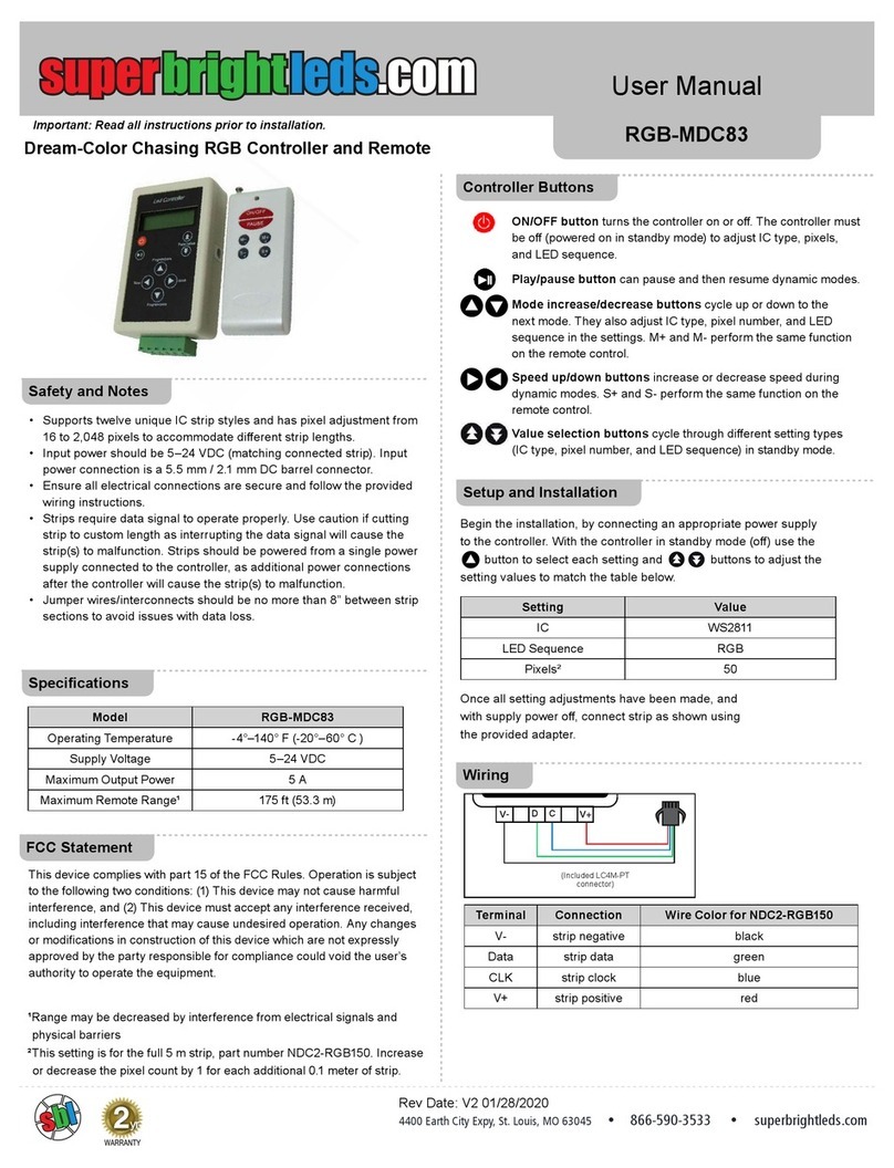
superbrightleds RGB-MDC83 User manual

superbrightleds

superbrightleds RGB-MDC83 User manual

superbrightleds LDRF-RGB8-TC3B User manual

superbrightleds

superbrightleds LDRF-RGB8-TC3B User manual

superbrightleds Dream-Color RGB-DC83 User manual

superbrightleds

superbrightleds Dream-Color RGB-DC83 User manual

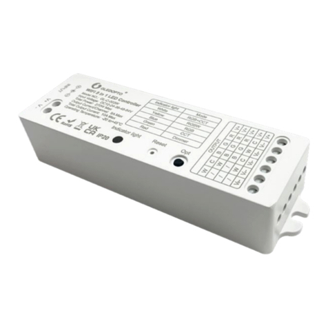
superbrightleds GL-C-001W User manual

superbrightleds

superbrightleds GL-C-001W User manual

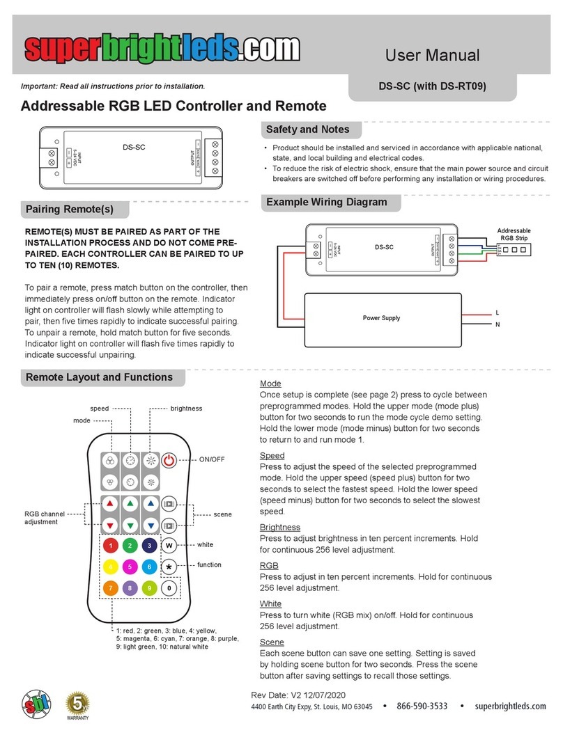
superbrightleds DS-SC User manual

superbrightleds

superbrightleds DS-SC User manual

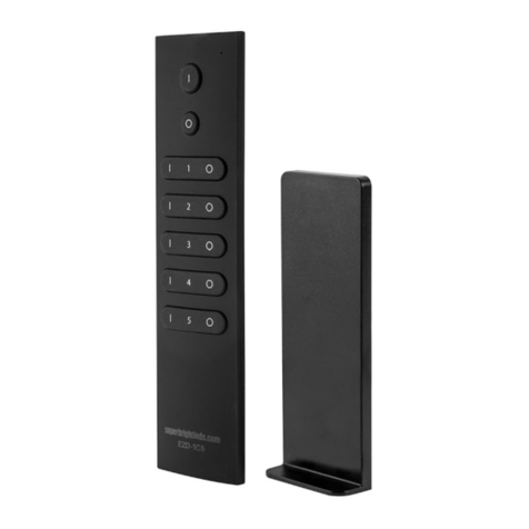
superbrightleds EZD-1C5 User manual

superbrightleds

superbrightleds EZD-1C5 User manual

superbrightleds WCBT-RGB10 User manual

superbrightleds

superbrightleds WCBT-RGB10 User manual

superbrightleds DS-CO4 User manual

superbrightleds

superbrightleds DS-CO4 User manual

Popular Controllers manuals by other brands

Neptune Technology TRICON SmartTrol Installation and maintenance guide

Neptune Technology

Neptune Technology TRICON SmartTrol Installation and maintenance guide

Radionics K6300-CNCII user guide

Radionics

Radionics K6300-CNCII user guide

Festo VPPI S1D Series manual

Festo

Festo VPPI S1D Series manual

Linak ACTUATOR LA36 manual

Linak

Linak ACTUATOR LA36 manual

Timotion ADJUSTME TDH3 user manual

Timotion

Timotion ADJUSTME TDH3 user manual

Lance TDC-100 Installation and operation manual

Lance

Lance TDC-100 Installation and operation manual

SOMFY animeo KNX 4 installation guide

SOMFY

SOMFY animeo KNX 4 installation guide

Zeva MC600C Assembly manual

Zeva

Zeva MC600C Assembly manual

Blue Sky Energy SOLAR BOOST 3024DiL Installation and operation manual

Blue Sky Energy

Blue Sky Energy SOLAR BOOST 3024DiL Installation and operation manual

INVT SV-DB100 Series Operation manual

INVT

INVT SV-DB100 Series Operation manual

Armatech MC163 manual

Armatech

Armatech MC163 manual

EFD ValveMate 7040 operating manual

EFD

EFD ValveMate 7040 operating manual

Desa SL-5326 user manual

Desa

Desa SL-5326 user manual

Ingersoll-Rand 150T P Series Installation and maintenance information

Ingersoll-Rand

Ingersoll-Rand 150T P Series Installation and maintenance information

Ingersoll-Rand SS815 Series Installation and maintenance information

Ingersoll-Rand

Ingersoll-Rand SS815 Series Installation and maintenance information

Ingersoll-Rand ST400 Series Maintenance information

Ingersoll-Rand

Ingersoll-Rand ST400 Series Maintenance information

McLelland MAP-1200PRE owner's manual

McLelland

McLelland MAP-1200PRE owner's manual

cashco 5381 Installation, operation & maintenance manual

cashco

cashco 5381 Installation, operation & maintenance manual

manuals.online logo
manuals.online logoBrands
  • About & Mission
  • Contact us
  • Privacy Policy
  • Terms and Conditions

Copyright 2025 Manuals.Online. All Rights Reserved.