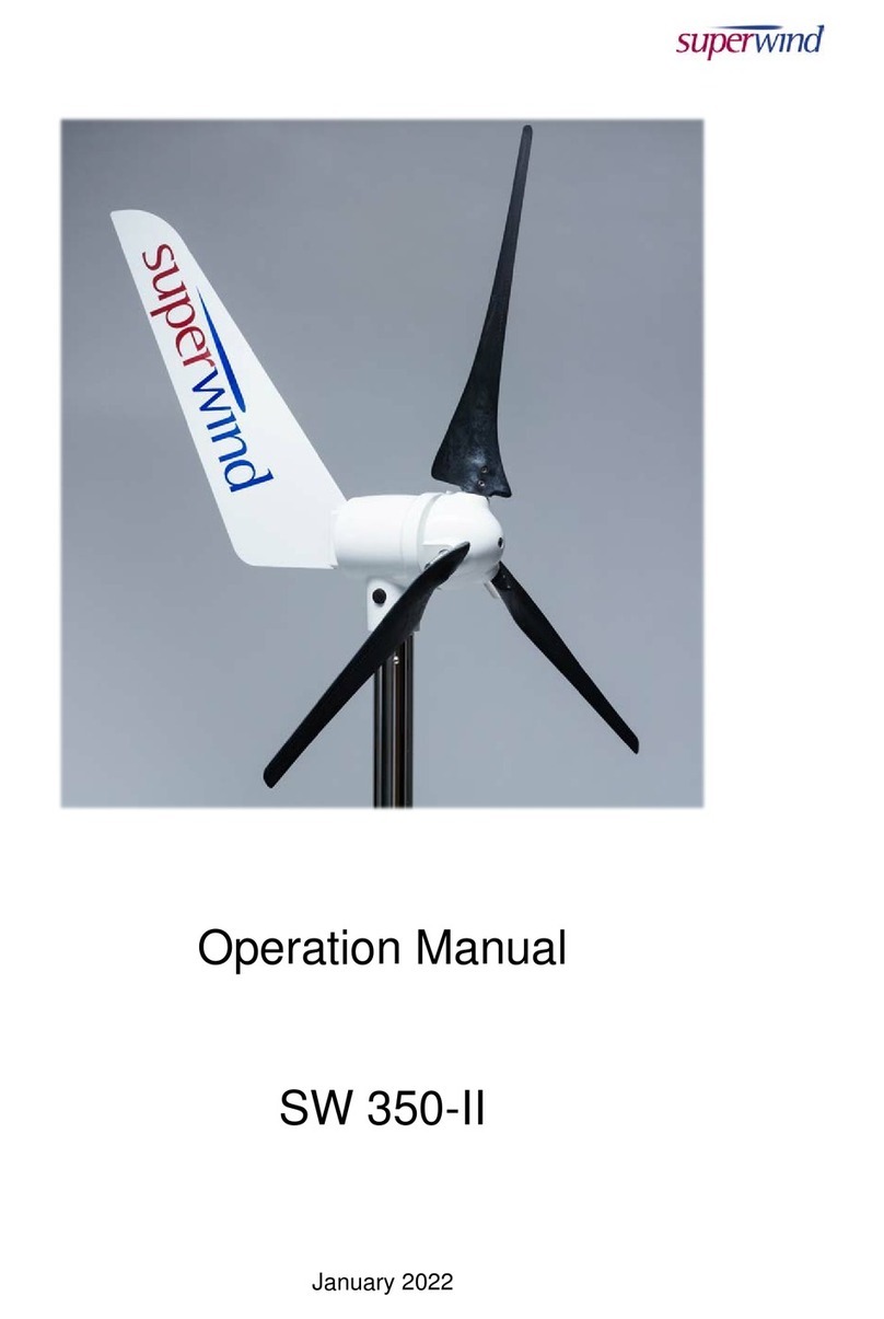
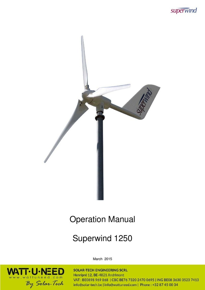
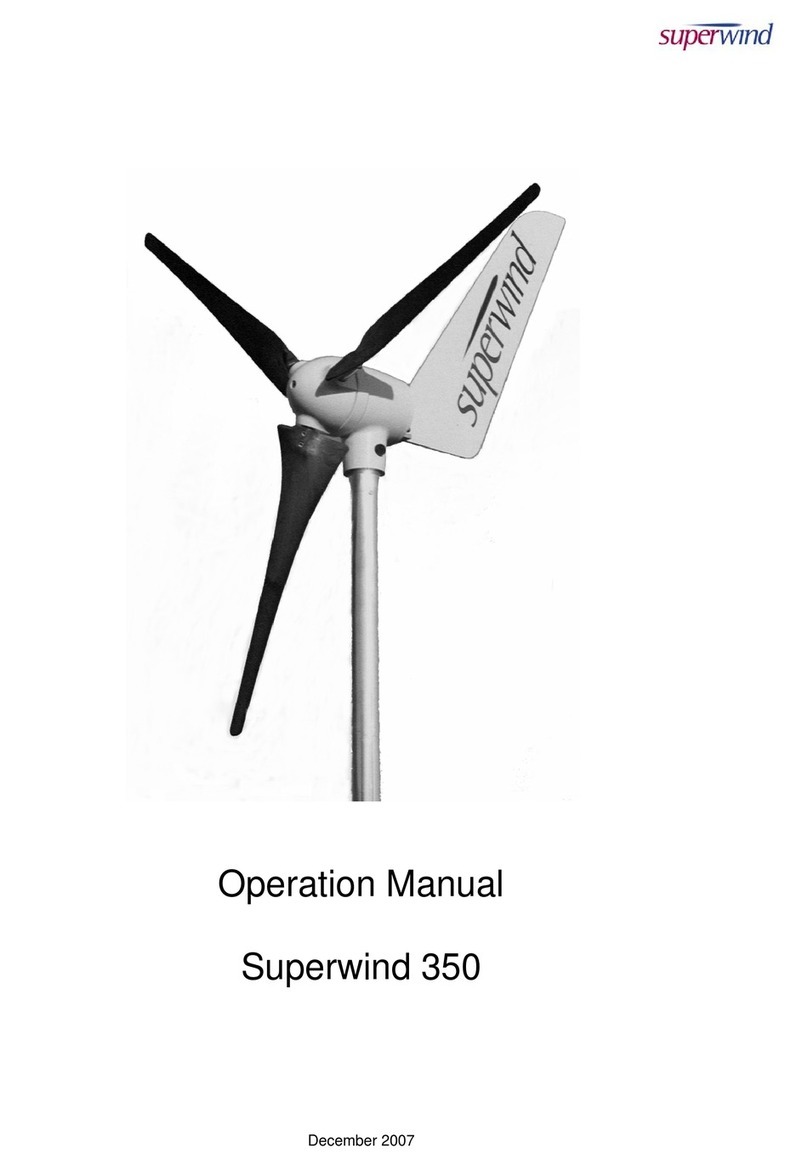
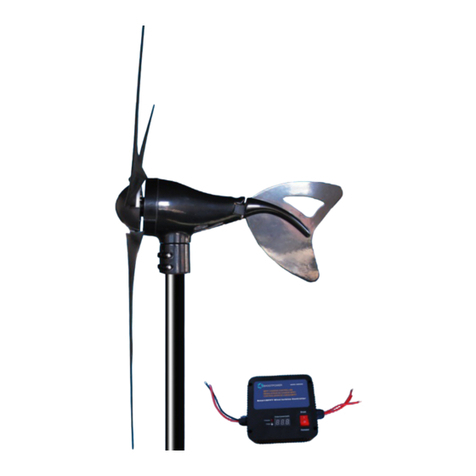
Superwind 350 12V User manual

www.superwind.com
Superwind 350 12V & 24V Manual
North, Central, and South America regions
01-2017

V 01-2017 www.superwind.com
1
Page intentionally left blank

V 01-2017 www.superwind.com
2
Thank you for purchasing a
Superwind 350.
Like all specialized commercial electrical generating equipment, it is important to
protect your investment by reviewing this manual in its entirety, paying particular
attention to all precautions and warnings.
Superwind micro-wind turbines are constructed of the highest quality materials
and have been designed for autonomous use in harsh conditions – but no matter
how well we construct the product, damage can be done to the turbine and/or
related systems (batteries, wiring, loads etc) if the integration is not well planned
and more importantly, installed correcty – as directed in this full version manual.
Should you have any questions regarding the installation or use of a Superwind
350 after reading this manual, PLEASE contact your closest Superwind installer,
distributor or superwind (the manufacturer) directly.
Your Superwind has been designed to provide many years of autonomous
service when properly installed.
INSTALLATION
PLEASE DO NOT PROCEED UNTIL
YOU HAVE READ
ALL INSTRUCTIONS
AND
SAFETY INFORMATION
© 2016 superwind GmbH.
Superwind is a Registered Trade Mark of superwind GmbH, Germany
MANUAL VERSION 01-2017
Replace previous version 10-2016

V 01-2017 www.superwind.com
3
Table of Contents
Section Description Page No.
OVERVIEW............................................................................................................... 2
Table of Contents.................................................................................................... 3
1. GENERAL INFORMATION AND REFERENCES
1.1. Company profile ............................................................................................ 5
1.2. Labelling ........................................................................................................ 5
1.3. Range of application ...................................................................................... 6
2. WARRANTY
2.1. Warranty......................................................................................................... 7
2.2. Warranty period ............................................................................................. 7
2.3. To obtain warranty service............................................................................. 7
2.4. Limitations...................................................................................................... 7
2.5. Others ............................................................................................................ 7
2.6. Expenses and Responsibilities ...................................................................... 8
2.7. Claims ............................................................................................................ 8
3. SAFETY INSTRUCTIONS
3.1. Potential sources of danger ........................................................................... 9
3.1.1. Mechanical dangers ....................................................................... 9
3.1.2. Electrical dangers........................................................................... 9
3.1.3. Dangers when mounting ...............................................................10
4. SPECIFICATIONS
4.1. Operational free space required ...................................................................12
4.1.1. Dimensions....................................................................................12
4.2. Technical data...............................................................................................13
4.3. Functional description / Special features ......................................................13
5. PREPARATIONS FOR ASSEMBLY
5.1. Packing list....................................................................................................15
5.2. Tools .............................................................................................................16
5.3. Optional accessories ....................................................................................16
5.4. Electrical components...................................................................................16
6. ELECTRICAL COMPONENTS AND CONNECTIONS
6.1. General information ......................................................................................17
6.2. Wiring diagrams ............................................................................................17
6.2.1. Recommended charge regulator....................................................17
6.2.1.1. SCR Marine Charge Regulator .......................................17
6.2.1.2. Diversion Load Resistor...................................................19
6.3. System components ....................................................................................19
6.3.1. Wires ..............................................................................................19
6.3.1.1 WAG Wire size chart for 12 Volt version .........................20
6.3.1.2 WAG Wire size chart for 24 Volt version .........................20
6.3.2. Strain relief ....................................................................................21
6.3.3. Polarity............................................................................................22
6.3.4. Batteries .........................................................................................22
6.3.4.1. Charging batteries ...........................................................22
6.3.4.2. SCR Marine charge regulator (with diversion load control). 24
6.3.4.3. Diversion load resistor .....................................................25
6.3.5. Fuses..............................................................................................25
6.3.6. Stop switch .....................................................................................25
6.4. Grounding .....................................................................................................26
7. SUPERWIND 350 GENERATOR ASSEMBLY
7.1. Precautions during mounting ........................................................................27
V 01-2017 www.superwind.com
4
7.2. Mast mounting ..............................................................................................28
7.2.1. Mast tube specifications ................................................................29
7.2.1.1 Common North American Mast Materials.......................29
7.2.1.2 Bushings .........................................................................29
7.2.2 Mounting the turbine on the mast ......................................................29
7.2.3 Preparations at the mast head...........................................................29
7.3 Mounting of the wind vane ...........................................................................31
7.4 Rotor assembly ............................................................................................32
7.4.1 Rotor blade hub assembly ................................................................32
7.4.2 Mounting the hub to the generator shaft............................................34
8 COMMISSIONING
8.1 Verification chart ...................................................................................................36
9 OPERATION
9.1 Safety instructions ........................................................................................37
9.2 RUN and STOP ...........................................................................................37
9.3 Power control ..............................................................................................38
9.4 Over-speed protection .................................................................................38
9.5 Annual power production ..............................................................................39
10 INSPECTIONS, MAINTENANCE
10.1 Periodic inspections ......................................................................................40
10.1.1 Rotor blades ..................................................................................40
10.1.2 Bolted connections .........................................................................40
10.1.3 Bearings, seals...............................................................................40
10.1.4 Slip rings.........................................................................................41
10.1.5 Corrosion protection ......................................................................42
10.1.6 Mast ...............................................................................................42
10.1.7 Electrical system ............................................................................42
10.2 Maintenance..................................................................................................42
11 TROUBLESHOOTING
11.1 Wind generator does not start.......................................................................43
11.2 No power output ...........................................................................................44
11.3 Insufficient power output ...............................................................................44
11.4 Battery is not fully charged............................................................................44
11.5 Checking the open circuit voltage.................................................................45
12 REPAIRS, SPARE PARTS
12.1 Repairs..........................................................................................................46
12.2 Spare parts list ..............................................................................................46
13 FREQUENTLY ASKED QUESTIONS
13.1 Basic use.......................................................................................................47
13.2 Installation .....................................................................................................47
13.3 Operation ......................................................................................................48
13.4 Troubleshooting ............................................................................................49
14 Abbreviations used in this manual ...............................................................................50
ATTACHMENT A – SUPERWIND STOP-SWITCH MOUNTING GUIDELINES..................51
ATTACHMENT B – SUPERWIND CHARGE CONTROLLER 12V (MARINE) SYSTEM....59
ATTACHMENT C – SUPERWIND CHARGE CONTROLLER 24V (MARINE) SYSTEM....69

V 01-2017 www.superwind.com
5
1. GENERAL INFORMATION AND REFERENCES
1.1 Company Profile
superwind GmbH was established in 2004 after four years of successful
research, design and testing of its now internationally patented micro-turbine
technology. Since then, thousands of commercially rated Superwind 350 (and
new Superwind 1250) turbines have been quietly providing reliable, autonomous
wind generated electricity to users in remote, harsh conditions on both land and
at sea world-wide.
As our reputation is as important as your satisfaction, we thank you in advance
for reading the Superwind manual in full – even before purchasing our wind
generating equipment. We also wish to remind you that wind turbines work best
when installed where there is sufficient wind, so please research your planned
wind turbine site or vessel installation to help predict how a Superwind 350 might
help with you power needs.
On behalf of our superwind staff and world joint venture partners, we thank you
for your interest in our cutting edge and real world proven wind turbines.
1.2 Labelling
This manual refers to the Superwind 350 wind generator.
Manufacturer:
superwind GmbH
Am Rankewerk 2-4
D-50321 Brühl
Germany
Tel.: +49 / 2232 / 577357
Fax: +49 / 2232 / 577368
Internet: www.superwind.com
The label providing the serial number and nominal voltage of your Superwind is
located at the yaw shaft (See Graphic No. 1.2).

V 01-2017 www.superwind.com
6
For future reference please record the serial number
of your Superwind 350 in the space provided below
prior to installation. Once the yaw shaft is inserted
into the mast this information will not be visible.
Type..................................................Superwind 350
Serial Number ..................................._____________
1.3 Range of application
The electric power generated by the Superwind charges batteries and can
directly be used for 12 VDC or 24 VDC-appliances (depending on the system
voltage). AC-appliances are supplied via an optional inverter. There is a wide
range of high quality 12 VDC or 24 VDC equipment available like energy saving
lamps, refrigerators, deep-freezers, water pumps, ventilators, consumer
electronics, TV, radio and navigation equipment, etc.
Examples of ideal applications include sailing yachts, campers, summer cottages,
mountain shelters, and industrial applications such as navigational aids, security
systems, environmental monitoring stations and communications. For rural
electrification the Superwind supplies basic power to families, schools, small
health care facilities, etc.
In many integration sites, energy supplies from sun and wind complement each
other. That is why the Superwind is used in wind / solar and in combination with
other charging systems to optimize the availability of power (at minimized battery
capacity).

V 01-2017 www.superwind.com
7
2 WARRANTY
2.1 Warranty
superwind GmbH warrants this product to be in good working order during the
warranty period. In the event that the product is found to be defective within the
warranty period, repair service will be provided free of charge by superwind
GmbH or an authorized service partner.
Free repair service may only be obtained by providing the warranty card and
original purchase invoice issued to the customer by the retailer. The warranty
card must state the purchaser s name, the retailer s name and address, the serial
number and the date of purchase of the product. superwind GmbH reserves the
right to refuse warranty service if this information is not complete or has been
removed or changed after the original purchase of the product from the retailer.
2.2 Warranty period
The warranty is valid for three years from the date of purchase by the purchaser,
as evidenced by the above mentioned documents.
2.3 To obtain warranty service
Warranty service is available at superwind GmbH and Superwind authorized
service partners. Any costs of secure transportation of the product to and from
superwind GmbH / Superwind authorized service partners will be borne by the
customer.
2.4 Limitations
superwind GmbH does not warrant the following:
Periodic check-ups, maintenance and repair or replacement of parts due to
normal wear and tear.
Defects caused by modifications carried out without superwind’s approval.
o Includes damage caused by improper use, handling or operation, in
particular defects caused by improper installation and installation on
inadequate masts or support structures.
Installation on inadequate masts or support structures (to obtain warranty
service the purchaser has to provide evidence that masts or support
structures are as recommended in the Superwind 350 manual).
Accidents or disasters or any cause beyond the control of superwind GmbH,
including but not limited to lightning, flooding, fire etc.
Costs for disassembly and reassembly of the product to enable shipment for
warranty reasons.
2.5 Others
Superwind GmbH reserves the right to decide whether the product or parts
thereof shall be repaired or replaced under warranty. Should neither repair nor
replacement by superwind GmbH be possible, the purchaser solely will be
entitled to a full or partial refund (prorated when returned to the manufacture after
more than 1 year of use).
This warranty does not affect the purchaser s statutory rights under applicable
national legislation in force, nor the purchaser s right against the retailer arising
from the sales / purchase contract. In the absence of applicable national
legislation, this warranty will be the purchaser s sole and exclusive remedy, and
superwind GmbH shall not be liable for any incidental or consequential damages
for breach of any expressed or implied warranty of this product.

V 01-2017 www.superwind.com
8
THE GENERAL CONDITIONS FOR THE SUPPLY OF PRODUCTS AND
SERVICES OF THE ELECTRICAL AND ELECTRONICS INDUSTRY APPLY
WITH APPROPRIATE LIMITS AND STANDARDS.
2.6 Expenses and Responsibilities
All associated expenses (shiping to and from the repair facility, insurance, etc)
are the full responsibility of the buyer or his shipping agent, unless the buyer is
notified otherwise by the manufacturer.
Upon receipt of your unit:
The crate should be opened and inspected immediately for damage.
Note any damage to the outside of the package (dents, scratches, etc.) and
document it on the Bill of Lading before signing and keep a copy.
Documenting damage with photos is also highly recommended.
Unpack the unit at once and perform a visual inspection to determine if it is
dented, bent or scratched.
If for any reason the unit should need to be returned, the original crate is the
best way to ship it back to the manufacturer.
2.7 Claims
Claims that occur during transportation must be filed by the consignee (the buyer)
as shipping terms are FOB-EX-WORKS (our distribution point as contracted).
BUYER IS RESPONSIBLE FOR ALL SHIPPING EXPENSES INCLUDING
CUSTOMS DUTIES AND VAT (IMPORT DUTIES).

V 01-2017 www.superwind.com
9
3 SAFETY INSTRUCTIONS
Please carefully study this manual before starting assembly and installation. The
information provided is to ensure your safety during mounting, operation, and in case of
trouble. If you have any additional questions please contact your dealer, a Superwind
service partner, or the manufacturer.
3.1 Potential sources of danger
Wind turbines in general – including small wind generators like the Superwind –
are electrical machines and thus potential sources of hazards.
3.1.1 Mechanical dangers
The main danger is the spinning rotor. The rotor blades are sharp and
can cause serious injuries, even at very low speed.
Never touch a spinning rotor.
Never try to stop the rotor by hand.
Do not mount the unit where personnel can come in contact with
the spinning rotor.
The rotor blades are made of carbon fiber reinforced plastic. This
material is extremely sturdy and enables your Superwind to cope with
heavy storms; however the rotor blades can break if any objects (e.g.
ropes, loose sail battens, branches etc.) come in contact with a spinning
rotor. The fragments of broken blades are sharp and can be thrown off of
the rotor at very high speed.
Protect the spinning rotor from impact with foreign objects.
For aerodynamic reasons the trailing edges of the rotor blades are very
thin and sharp.
Be careful when unpacking and handling in order to avoid injuries
as well as damage to the blades.
3.1.2 Electrical dangers
The generator can produce dangerous open circuit voltages up to 52
VDC (12 V version) and 105 VDC (24 V version) at no-load operation if
the electrical connection to the battery or consumer (load) is interrupted.
This open circuit voltage will be reached at a wind speed of
approximately 35 m/s.
The charging current will reach up to 30 Ampere DC (12 V version) or 15
Ampere DC (24 V version)! All wires, electrical components and
connectors must be rated for 40 Amps (12 V version) or 20 Amps (24 V
version). For correct dimensioning (gauge) refer to Section 6, Tables
6.3.1.1 and 6.3.1.2 on page 19.

V 01-2017 www.superwind.com
10
Smaller gauged wires with insufficient cross section
(diameter) will get extremely hot and can cause an electrical
fire.
To reduce installation problems, keep wire runs as short as practical and
mount all system components as close to the battery as possible. For
details see Section 6.2 on page 17
NEVER SHORT-CIRCUIT THE BATTERY. Doing so can
cause serious damage to the battery and wiring, such as fire,
explosion, and the release of acid toxic gases.
Be extremely careful to never short-circuit the battery.
Charging lead-acid batteries can produce dangerous
flammable gas. Unsealed lead-acid batteries have vent holes
releasing hydrogen during charging, which can form potentially
explosive gases in enclosed areas. A small spark (such as
from an electrical switch) can detonate this explosive gas
mixture. To prevent such explosions always provide sufficient
ventilation in battery storage areas.
Never install batteries in locations where the danger of sparks
exist.
Provide sufficient ventilation for batteries at all times.
The diversion load (power resistor) of the Superwind 350 charge
regulator (SCR type) can become very hot. This device requires
adequate space and ventilation to prevent the resistor from overheating.
To prevent damage to the device and to protect against fire, never mount
the power resistor on flammable surfaces or close to flammable
materials.
Never install the power resistors on a flammable surface.
3.1.3 Dangers when mounting
These instructions also apply during disassembly, when conducting
checks or other work carried out on your wind generator.
Only use mast and support designs capable of safely withstanding the
loads of your wind generator. The mast not only has to withstand your
wind generator’s weight and mass moment of inertia (e.g. on a sailing
yacht) but also the considerable thrust caused by high wind speed. For
details see Section 7 on page 27.
Work on the mast or on your wind generator only on a calm and windless
day. Do not step beneath or stand under hanging loads (e.g. a tilted
mast) and prevent other persons from doing so.

V 01-2017 www.superwind.com
11
Ensure that all batteries are disconnected from the system prior to
conducting any work.
Prevent your wind generator from starting unintentionally (turning in a
direct wind) during mounting by turning off the safety switch or short
circuiting the generator output wires (Red and Black).
Disconnect the battery before INSTALLATION! Short-circuit
the two generator OUTPUT WIRES (Graphic No. 3.1.3)
(Caution: Do this only AFTER disconnecting the battery!)
and/or loosely tie one blade to the mast without pressure to
prevent the blade from spinning during installation.
Never tie a rotor blade to the mast for long periods of time as
this will distort the aerodynamic design of the blade, resulting
in vibrations during operation which could damage the
generator.
Never approach a spinning rotor.
Never try to stop a spinning rotor by hand.
Never install the wind generator in areas where it can be
easily reached or approached by anyone while walking or
working around the turbine structure.

V 01-2017 www.superwind.com
12
4. SPECIFICATIONS
4.1 Operational Free Space Required
The area where the Superwind turbine will be installed must be considered
carefully. Operational space for the turbine itself, as well as the working area
(including the mast and support) must be free from obstructions such as nearby
trees, walls or buildings, sailing equipment, etc. It is imperative that the turbine
operational area is completely unobscured and open to the wind to achieve
maximum energy production.
Wind turbine operations and safety are both optimized by careful preinstallation
planning. Clear, open air space provides the best air flow and performance, but
even ideal locations can be impacted by future changes to the area. Wind power
is dramatically affected by nearby structures, obstacles (growing trees, ship
bimini covers, etc), and even the turbine’s own mast structure. As such, it is
important for the installation to be designed with the end result and proper
integration in mind – such as including the highest practical mast top with the
clearest safety zone possible.
4.1.1 Dimensions
Dimensions
Table No. 4.1.1 mm
a Distance between center of mast and blade tip 168
b Distance between center of mast and extreme upper part of wind vane 556
c Distance from mast-top to center of rotor 136
d Distance from the center of hub and extreme upper part of the wind vane 530
e Length of yaw shaft 76
f Rotor diameter including blades 1220
g Outside diameter (OD) of yaw shaft with damping rings 44
h High for Plastic Bushing to be inserted into mast 71
i Required space for yawing 1263

V 01-2017 www.superwind.com
13
4.2 Technical data
nominal power...................................350 W
nominal wind speed ..........................12,5 m/s
cut in wind speed ..............................3,5 m/s
cut off wind speed .............................none
rotor diameter....................................1,20 m
number of blades ..............................3
blade material ...................................carbon fibre reinforced plastics
rotor speed........................................500 – 1300 rpm
generator ..........................................permanent magnet 3-phase with rectifier
magnets Neodymium
nominal voltage.................................12 V DC or 24 V DC
speed regulation ...............................rotor blade pitch
power regulation ...............................rotor blade pitch
brake .................................................dynamic, short circuit
weight................................................11,5 kg
rotor thrust (operation) ......................70 N (15.7 lbf)
rotor thrust (extreme wind speed).....220 N (49.5 lbf)
4.3 Functional description / Special features
The Superwind, like all wind turbines, uses part of the kinetic energy of the wind
and converts it into electricity.
The power is approximately proportional to the cube of the wind speed - i.e.
doubling the wind speed results in eight times higher power output. Therefore,
power from the wind at low wind speeds produces very little energy. However, as
the wind speed increases exponentially, high pressure suddenly impacts the
turbine and all of its mechanical components. During high wind events,
conventional wind turbine technology resulted in the turbine going into an “over-
speed” condition, damaging both internal electrical components as well as the
blades themselves.
To design the Superwind, special technologies were developed in order to
achieve optimum power output for a wide wind speed range, as well as maintain
maximum safety in high wind or storm conditions. The following technology has
been incorporated into the Superwind to achieve this performance.
a) The rotor blades were developed using modern computerized calculation and
simulation methods. The airfoil had been wind tunnel tested and was specifically
developed for small size rotors.
Relatively broad rotor blades combined with a special pitch angle produces a
high start-up torque, enabling the rotor to start at only 3.5 m/s wind speed.
Optimum start-up performance will be reached after a
mechanical run-in period of the bearings and their seals. This
‘break-in’ period will vary depending on the winds speed and
hours the turbine is left “on” in windy conditions.
When using the Superwind for battery charging, do not mistake rotor start-up for
the start of charging. The wind speed required to start charging the battery
depends on the battery charge load at the time and might be slightly higher than
the rotor start-up wind speed.
The term ‘cut in speed’ describes when the turbine can start producing power to
charge your batteries. This is a higher wind speed than the ‘start up wind speed’,
a lower wind value where your turbine may spin, but will not be producing power.

V 01-2017 www.superwind.com
14
At superwind, we focus on power production and not just turning blades. As such,
keep in mind that the wind speed required to start charging the battery depends
on the battery state of charge (load) and other basic electrical system factors.
Your turbine has extremely high quality bearing sets to provied
a long, nearly maintenance free service life. These special
bearings require a “ break in period“ of weeks or possibly
months to achieve the highest charging levels at lower wind
speed conditions. Leaving the Superwind turbine in the
autonomous “Run” position through all types of weather,
including high winds and storms, will help shorten this break in
period.
b) The basic innovation of Superwind is its novel aerodynamic rotor control system.
Similarly to large wind turbines, it adjusts the pitch angle of the rotor blades.
The mechanical controller is fully integrated into the hub and works without
expensive electrical or hydraulic components. Instead, the controller is actuated by
forces arising at operation of the wind turbine itself.
The forces are affected by the geometric and kinematic lay-out of the rotor and
controller mechanism.
Aerodynamic forces act as a control variable to adjust the rotor blades for power
regulation above the nominal wind speed. Centrifugal forces are the second control
variable for the rotor blade adjustment. By the special arrangement of both force
components, the controller limits rotor speed automatically (even at extreme wind
velocities) and protects the wind turbine from over-speed, even during no-load
operation. As a result, the controller limits the mechanical loads at high wind speed,
providing smooth operation under all weather conditions.

V 01-2017 www.superwind.com
15
5. PREPARATIONS FOR ASSEMBLY
5.1 Packing list
Please check your delivery for completeness and transport damage.
PACKING LIST
Table 5.1
ITEM DESCRIPTION SIZE QUANTITY 5
1 Generator unit 1
2 Hub 1
3 Wind vane 1
4 Rotor blade 3
5 Wind vane mounting plate 1
6 Plastic bushing (optional stainless steel
bushing)
1
7 Socket cap screw M8 x 80 1
8 Socket cap screw M8 x 20 2
9 Socket cap screw M6 x 25 (TUFLOK) 6
10 Socket cap screw with rubber ring M6 x 8 (TUFLOK) 3
11 Hexagon socket button head screw M6 x 12 2
12 Hexagon socket button head screw M6 x 6 2
13 Allen key 6 mm 1
14 Allen key 5 mm 1
15 Allen key 4 mm 1
16 Operation’s manual 1

V 01-2017 www.superwind.com
16
For aerodynamic reasons the rotor blades trailing edges are
very thin and sharp. Use caution when unpacking, both to avoid
injury and damage to the blades.
5.2 Tools
A set of allen keys is included to assist with the installation of your Superwind.
The following is a list of additional recommended tools:
1. screw drivers
2. set of spanners
3. wire strippers
4. wire crimpers
5. heat shrink or electrical tape
6. multimeter
For correct tightening of the screws, a torque wrench is recommended.
Tools for the mast installation are not listed here. See respective instructions.
5.3 Optional accessories
Mast-sets:
Mast-set for yachts
Mast-set for land installation / guyed tubular mast 6 m (other heights on
request)
Mast-set for land installation / self-supporting tubular mast 7,5 m
5.4 Electrical components:
Charge regulator SCR Marine incl. power resistor
20 Amps (24 V System) or 40 Amps (12 V System), slow-blow fuses or
breaker
Fuse holder
Stop-switch
Ammeter

V 01-2017 www.superwind.com
17
6. ELECTRICAL COMPONENTS AND CONNECTIONS
6.1 General information
Ensure that any installation or repair work on the electrical system is carried out
by qualified technicians only. These technicians must also read these instructions
prior to starting the installation!
Careful pre-installation planning is a crucial first step in the
installation of your new Superwind, as well as other
system components that are also part of your project.
The actual electrical connection should be made during the
lasts steps of the installation.
Make sure that the batteries and other charging sources (such
as grid or shore power) are disconnected until the installation
is complete.
6.2 Wiring diagrams
6.2.1 Recommended charge regulator
6.2.1.1 SCR Marine Charge Regulator (12V or 24V, depending on
turbine and system voltage, Graphic No. 6.2.1.1)
The SCR Marine charge regulator has been especially designed for use
with the Superwind 350 wind generator. It allows the user to fully charge
batteries, while also protecting battery banks from overcharging via a
diversion load control, as well as temperature compensation.
Wind charge controllers are very different from solar charge controllers in
that they are designed to electrically maintain the load correlation with
the battery bank while simultaneously producing power above the ever
changing battery state of charge. This allows the batteries to be properly
charged based on ideal temperature-compensated charging rates and
consumer demands.
The Diversion mode initiates when the batteries have reached their
maximum charging voltage; the SCR Marine´s PWM circuit automatically
diverts the wind turbine´s surplus power to the diversion resistor block.
With this technology, even when batteries are fully charged, the wind
turbine continues operating (provides useable power generated when
there is ample wind) providing real time power to other electric
consumers (loads) as they come online automatically or when switched
on manually.
This ‘Diversion State’ (dumping generated power) is indicated by an LED
illuminating (turning on) on the SCR Controller when the battery bank is
full – indicating that electric power (above and beyond the battery bank
charging needs) is available to be used rather than dumped.

V 01-2017 www.superwind.com
18
The SCR Marine Charge Controller is suitable for charging lead acid
batteries, gel batteries and AGM batteries (AGM = Absorbed Glass Mat)
and some Lithium Ion batteries (NOTE: consult your Superwind
Customer Service Contact and the battery manufacturer for important
specific details before trying to charge Lithium Ion Batteries!). For special
applications, the maximum charging voltage can be adjusted to customer
requirements by superwind.
The SCR Marine charge regulator is completely sealed and protected
against moisture (such as found in a marine environment) however it is
not waterproof and should be installed in a suitable weather proof
outdoor control panel or located in an appropriate dry space aboard ship.
The SCR Marine charge regulator has the ability to charge two separate
battery banks independently, yet still work in diversion mode when both
battery banks are in a full state of charge (eg. starter battery set and the
house battery bank on a yacht).
IMPORTANT:
An advantage of using the SCR Charge Controller is that it can work
alongside other charging technologies such as solar panels, diesel
generators, fuel cells, engine power (from the alternator), and even
shore power (aboard ship or at a site) without affecting other
operations.
Please contact your Superwind customer service contact for special
configuration information or more details.

V 01-2017 www.superwind.com
19
6.2.1.2 Diversion Load Resistor
The resistance of the cable that connects the load resistor with the
charge regulator can affect the charging voltage. Therefore, the
connecting resistor wire run should not exceed 1 meter with the
recommended wire gauge. If you would like to extend the resistor wire
beyond 1 meter, please refer to the AWG Wire Size Chart (Table No.
6.3.1.1 and 6.3.1.2).
Charge regulators are not protected against reversed polarity of
the wires (“+” & “-“), and will be damaged if connected
incorrectly! Connecting the wrong wire (line) polarity to your
Charge Controller will void the warranty!
Do not reverse the polarity of the wires.
If you want to use a different charge regulator than what is recommended
for use with your Superwind 350 (the SCR Marine charge controller: 12v
or 24v), make sure that it is a suitable shunt-regulator based device with
full time diversion load control. To insure you are not voiding the warranty
on your Superwind turbine, please ask your Superwind customer service
contact as many other charge controllers - especially those used for solar
photovoltaic systems - are unsuitable, since they interrupt the electric
circuit for voltage regulation and can render the wind generator into a
dangerous no-load operation!
6.3 System components
6.3.1 Wires
The cross sections (gauge) of the wires required depends on their length
and the rated voltage of your wind generator. After selecting the location
of the mast, measure the distance from the mast top to the battery and
then select the minimum cross section required on the basis of the
following tables. In order to keep the power loss of the lines as small as
possible, do not use lines with under-sized cross sections.
It is always
recommended
to use
stranded
(braded) wire.
Solid wire
should be
avoided.
This manual suits for next models
1
Table of contents
Other Superwind Wind Turbine manuals