SUTO S 120 Manual

English
Instruction and operation manual
S 120
Oil vapor sensor

Dear Customer,
Thank you for choosing our product.
The operating instructions must be read in full and carefully observed
before starting up the device. The manufacturer cannot be held liable
for any damage which occurs as a result of non-observance or non-
compliance with this manual.
Should the device be tampered with in any manner other than a
procedure which is described and specified in the manual, the warranty
is cancelled and the manufacturer is exempt from liability.
The device is destined exclusively for the described application.
S TO offers no guarantee for the suitability for any other purpose.
S TO is also not liable for consequential damage resulting from the
delivery, capability or use of this device.
2 S 120

Table of contents
1. Safety instructions.......................................................................5
2. Application.................................................................................7
3. Features.....................................................................................7
4. Technical Data............................................................................8
4.1 General.................................................................................8
4.2 Electrical Data........................................................................8
4.3 Output-Signals.......................................................................8
4.4 Accuracy ..............................................................................9
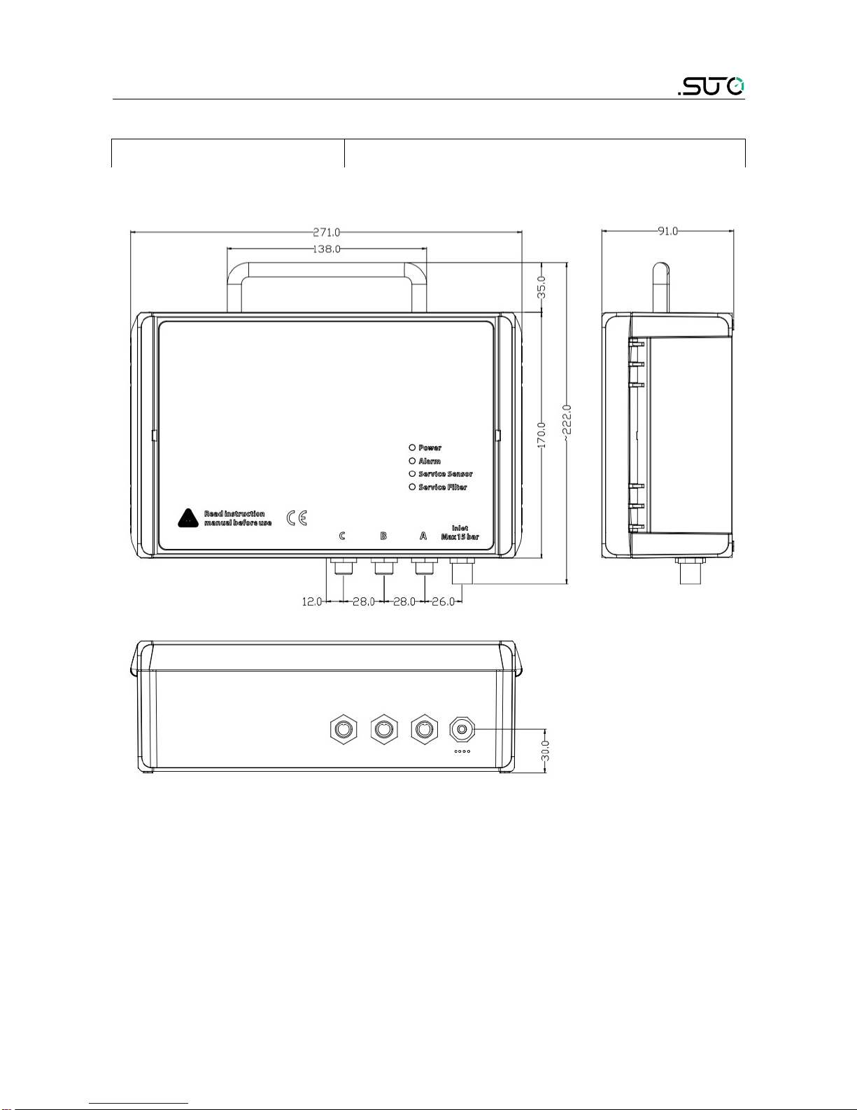
5. Dimensional drawing....................................................................9
6. Installation ..............................................................................10
6.1 Installation Requirements......................................................10
6.2 Wall mounting instructions ....................................................11
6.3 Installation Procedure............................................................12
6.4 Electrical connection ............................................................13
7. Configuration ...........................................................................14
7.1 Configuration without display ................................................15
7.2 Configuration with external display .........................................15
7.3 Configuration with internal display..........................................15
8. Operation with internal display ...................................................15
8.1 ser interface ......................................................................15
8.2 Main menu .........................................................................16
8.3 Description of display icons in status bar .................................17
8.4 Sensor settings ....................................................................17
8.4.1 Basic setting...................................................................18
8.4.2 Altitude settings .............................................................18
8.4.3 Analog output ................................................................18
8.4.4 Modbus settings..............................................................19
8.4.5 Alarm settings................................................................20
8.4.6 Status...........................................................................20
8.5. Logger................................................................................21
8.6 Files....................................................................................22
8.7 Service info .........................................................................22
8.8 System settings ...................................................................23
8.9 Communication ...................................................................23
9. LED indicators at front panel ......................................................24
9.1 S 120 error indications and display indications .........................24
10. Signal outputs.........................................................................25
10.1 Analog output ....................................................................25
10.2 Digital output ....................................................................25
10.3 Alarm output .....................................................................26
11. Optional extra accessories.........................................................27
S 120 3

11.1 Sensor display (optional).....................................................27
11.2 Service kit .........................................................................27
12. Calibration..............................................................................28
13. Maintenance............................................................................28
14. Disposal or waste.....................................................................28
15. Warranty................................................................................29
4 S 120

1. Safety instructions
Please check if this instruction manual accords to the
product type.
Please observe all notes and instructions indicated in this
manual. It contains essential information which have to be
observed before and during installation, operation and
maintenance. Therefore this instruction manual has to be read carefully
by the technician as well as by the responsible user / qualified
personnel.
This instruction manual has to be available at the operation site of the
oil vapor sensor at any time. In case of any obscurities or questions,
regarding this manual or the product, please contact the manufacturer.
WA NING!
Compressed air!
Any contact with quickly escaping air or bursting
parts of the compressed air system can lead to
serious injuries or even death!
•Do not exceed the maximum permitted pressure range (see
sensors label).
•Only use pressure tight installation material.
•Avoid that persons get hit escaping air or bursting parts of the
instrument.
•The system must be pressureless during maintenance work.
WA NING!
Voltage used for supply!
Any contact with energized parts of the product, may
lead to a electrical shock which can lead to serious
injuries or even death!
•Consider all regulations for electrical installations.
•The system must be disconnected from any power supply during
maintenance work.
•Any electrical work on the system is only allowed by authorized
qualified personal.
S 120 5

1. Safety instructions
WA NING!
Permitted operating parameters!
Observe the permitted operating parameters, any
operation exceeding this parameters can lead to
malfunctions and may lead to damage on the
instrument or the system.
•Do not exceed the permitted operating parameters.
•Make sure the product is operated in its permitted limitations.
•Do not exceed or undercut the permitted storage and operation
temperature and pressure.
•The product should be maintained and calibrated frequently, at
least annually.
General safety instructions
•It is not allowed to use the product in explosive areas.
•Please observe the national regulations before/during installation
and operation.
emarks
•It is not allowed to disassemble the product.
ATTENTION!
Measurement values can be affected by malfunction!
The product must be installed properly and
frequently maintained, otherwise it may lead to
wrong measurement values, which can lead to
wrong results.
Storage and transportation
•Make sure that the transportation temperature of the device is
between -30°C ... 70°C.
•For transportation it is recommended to use the packaging which
comes with the device.
•Please make sure that the storage temperature of the device is
between -20°C ... 50°C.
•Avoid direct V and solar radiation during storage.
•For the storage the humidity has to be <90%, no condensation.
6 S 120

2. Application
2. Application
The S 120 is an oil vapor sensor which is designed to monitor oil
contents of compressed air and gases within the permissible operating
parameters. These parameter can be found in the technical data
section.
The S 120 oil vapor sensor is not developed to be used in explosive
areas. For the use in explosive areas please contact the manufacturer.
The S 120 oil vapor sensor is mainly used in compressed air systems in
industrial environment.
3. Features
•Measures oil vapor contents in compressed air and other gases.
•Easy connection through sampling hose and quick connect.
•Can be used for permanent or in portable applications.
•Measures dorm to 0.001 mg/m3.
•PID sensor for highest accuracy.
•Service and alarm indication through LED.
•Connectable to display and data logger of the manufacturer as
well as third parties displays and control units.
•IP65 casing provides robust protection in rough industrial
environment.
•Optional display directly on the sensor, showing the actual values.
S 120 7

4. Technical Data
4. Technical Data
4.1 General
Parameters Standard unit oil vapor contents: mg/m3
Principle of measurement Photo ionization
Sensor PID (photo ionization detector)
Measuring medium Compressed air and gases free of corrosive,
aggressive, caustic and flammable
constituents
Measuring range 0.003 ... 10 mg/m3
Sample flow range < 2 l/min, measuring gas is released to
ambient
Operating temperature -20°C ... 50°C
Humidity of the meas.
medium
< 40% rel. humidity, no condensation
Operating pressure 3 ... 15 barg (higher pressure on request)
Low pressure (optional) 0.5 ... 2 barg
Housing material PC, Al alloy
Protection class IP65
Dimensions See dimensional drawing on the next page
Display (optional) 5” graphic display with touch interface
Weight 2.4 kg
Sensor durability 6000 operating hours
4.2 Electrical Data
Power supply 24 VDC ± 5%, 10W
4.3 Output-Signals
Analogue output 4 ... 20 mA
Digital output RS-485, Modbus / RT
Alarm output Relay, NO, 60V, 1A
8 S 120

4. Technical Data
4.4 Accuracy
Accuracy 5% of reading ± 0.003 g/
5. Dimensional drawing
S 120 9

6. Installation
6. Installation
Please make sure that all components listed below are included in your
package.
Qty Description Item No.
1 S120 oil vapor sensor S604 1201/
S604 1202/
S604 1203
3 M12 connectors C219 0059
1 1.5 m teflon hose with fast connector A554 0003
1 Coalescing filter A554 1203
1 Mounting brackets No P/N
1 Instruction manual No P/N
1 Calibration certificate No P/N
6.1 Installation equirements
There is two versions of the S 120:
•S 120 for stationary use. The stationary version comes with four
mounting brackets which can be mounted from the backside of the
instrument at each corner. This allows an easy installation at a
wall.
•S 120-P for portable use. The portable version comes in a
transport case.
10 S 120

6. Installation
6.2 Wall mounting instructions
The device can be mounted on the wall using the supplied brackets.
Please use one of the attached dimensions to prepare your holes.
S 120 11

6. Installation
6.3 Installation Procedure
The following steps explain the procedure of an appropriate installation.
1. Connect the teflon hose with
the inlet of the S 120 like
shown in the picture.
2. Connect the other end of the
teflon hose with a quick
connector. The teflon hose
with quick connector is used
to connect the S 120 to the
process.
Please consider the following recommendations for a successful
measurement result:
•All components from the sampling point to the S 120 must oil and
grease free.
•Ambient and gas temperature must be within the specified ranges.
•The inlet gas must be pressurized with the valid ranges.
12 S 120

6. Installation
•The sampling gas mus be dry (< 40% RH) and clean.
•Ensure that valves at the sampling point are not lubricated.
ATTENTION!
Avoid contamination with oil or grease!
It will lead to very slow measurement or impossible
measurement results!
6.4 Electrical connection
Connection to the following external display units
S 120 Colour
code
S 330 / 331 S 320
Pin Signal Termina
l
Pin Termina
l
Pin
A.1 SDI brown
A
1
G
6
A.2 / B.2 -Vbwhite 2 7
A.3 / B.3 +Vbblue 3 8
A.4 / C.4 +D black 4
A.5 / C.5 -D grey 5
B.1 PE brown GND
A.1 SDI brown
B
1
A.2 / B.2 -Vbwhite 2
A.3 / B.3 +Vbblue 3
A.4 / C.4 +D black 4
A.5 / C.5 -D grey 5
B.1 PE brown GND
S 120 13

6. Installation
Connection to third party displays and control units
Connector Pin 1 Pin 2 Pin 3 Pin 4 Pin 5
A SDI -Vb+Vb+D -D
B PE -Vb+Vb+I -I
C Relay Relay GND +D -D
brown white blue black grey
Legend to pin assignment
SDI Digital signal (internal use)
-VBNegative supply voltage
+VBPositive supply voltage
+l Positive 4...20 mA signal
-I Negative 4...20 mA signal
+D RS-485, modbus / RT
-D RS-485, modbus / RT
Relay Alarm output
PE Earth connection
GND Communication ground
7. Configuration
The S 120 is delivered with standard ex-work configuration or with
specific customer settings according to the order.
Standard ex-work configuration
Scaling : 4 mA = 0.000 mg/m3
20 mA = 10.000 mg/m3
Alarm : 1.000 mg/m3, up
Oil type : Isobutene
Modbus : Device address = 1
Baudrate = 19200
Framing/parity/Stop bit = 8, N, 1
Transmission mode = RT
14 S 120

7. Configuration
7.1 Configuration without display
Other configurations as the ex-work configuration can be programmed
by the service kit.
7.2 Configuration with external display
Please see the instruction manual of the S 330/331.
7.3 Configuration with internal display
Please see sensor settings in the next chapter.
8. Operation with internal display
8.1 User interface
The screen below shows the user interface of the S 120.
S 120 15

8. Operation with internal display
1. On the left site the online measuring result is shown:
•Oil vapor: oil vapor content per cubic meter at reference
condition
•Temperature: sensor casing temperature
•Pressure: pressure at the sensor
•Status: sensor status (for service)
2. On the right site the online graphic view is shown
3. Press the “Home”button to get back to the home view which is
shown above.
4. Press the “Graphic” button to show the graphic in full screen.
5. Press the “Value” button to show the values in full screen.
6. Press the “Menu” button for further operations. Please see main
menu in the next chapter.
7. Press the screenshot button to create an image of the current
screen which is stored inside of the memory and can be read out
through CSM-S software.
8.2 Main menu
Quick buttons
Status
bar
Function
buttons
16 S 120

8. Operation with internal display
The menu consists of the following sub-menus:
Sensor settings Settings related to the connected sensors.
Location setting Settings are fixed.
Logger S 120 data logger settings.
Files All recorded files and the memory status can be
checked.
Service info seful information in case of a service issue.
Service setting Many different settings are under this menu.
Communication Modbus master, field bus RS-485
8.3 Description of display icons in status bar
SB stick connected System error
Sensor connection has
changed, not matching
with configuration
Sensor unit is not
matching with
configuration
Logger status RTC backup battery
status
Sensor calibration is
expired SB to PC connected
Alarm triggered
8.4 Sensor settings
This chapter describe the available settings for the S 120. After
selecting of “sensor setting”, the next screen will show the following
available setting:
S 120 17

8. Operation with internal display
8.4.1 Basic setting
1. Altitude: Please enter the Altitude.
2. ser slope: please adopt the value in which is shown in the
picture.
3. Compressor oil: Choose the oil of your compressor. If your oil is
not available please choose custom oil and input the response
factor (for further assistance please contact the manufacturer of
your oil). If it is not sure which oil is in use please choose
synthetic oil.
4. Output unit: Choose the desired output unit.
5. Click save.
8.4.2 Altitude settings
For an accurate oil vapor measurement you have to input you altitude.
Valid values are only positive. If you are in a location where the real
altitude is negative, please just enter 0 instead of a negative value.
8.4.3 Analog output
Please set scaling of analog output and click save. Whenever the output
unit is changes, it is recommended to adjust the scaling of the analog
output.
18 S 120

8. Operation with internal display
8.4.4 Modbus settings
Please do not change the modbus settings.
S 120 19

8. Operation with internal display
8.4.5 Alarm settings
Please enter the desired threshold of oil vapor to activate the alarm.
8.4.6 Status
The status show you useful information in case of s service issue.
20 S 120
Other manuals for S 120
2
Table of contents
Other SUTO Accessories manuals
Popular Accessories manuals by other brands

Silvercrest
Silvercrest SFKS 2 B1 operating instructions

Dometic
Dometic COOLPRO TC 14 Operation manual

Emos
Emos B0541 quick start guide

Makita
Makita CW004G instruction manual

S+S Regeltechnik
S+S Regeltechnik THERMASGARD HFTM-VA Series Operating Instructions, Mounting & Installation

Hamach
Hamach Powerline 600 Mbps Set operating instructions