Suzuki 990E0-54P56-000 User manual

Description: Front parking system Part number: 990E0-54P56-000
Applications: VITARA (LY)
Fitting time: 1h
Beschreibung: ParkAssistent vorn Teile Nr: 990E0-54P56-000
Verwendung: VITARA (LY)
Montagezeit: 1h
Désignation: Système d'aide au stationnement avant N° de code: 990E0-54P56-000
Utilisations: VITARA (LY)
Temps de montage: 1h
Descrizione: Sensori di parcheggio anteriori Numero di codice:
990E0-54P56-000
Applicazioni: VITARA (LY)
Tempo
d’installazione:
1h
Descripción: Sensores de aparcamiento delanteros Código:
990E0-54P56-000
Aplicación: VITARA (LY)
Tiempo de
instalación:
1h
Περιγραφή: Εμπρόσθιοι αισθητήρες στάθμευσης αρ. κωδικού: 990E0-54P56-000
Εφαρμογές: VITARA (LY)
Χρόνος
εγκατάστασης:
1h
INSTALLER AND USER INSTRUCTIONS
MANUALE DI INSTALLAZIONE ED USO
INSTALLATIONS-UND BEDIENUNGSANLEITUNG
MANUAL PARA INSTALADOR Y USUARIO
MANUEL INSTALLATEUR ET UTILISATEUR
GB
ΕΓΧΕΙΡΙΔΙΟ ΕΓΚΑΤΑΣΤΑΣΗΣ ΚΑΙ ΧΡΗΣΗΣ
F
D
I
E
GR
TELEPÍTÉSI ÉS KEZELÉSI UTASÍTÁSOK
INSTRUKCJA MONTAŻU I OBSŁUGI
INSTALLERINGS- OG BRUGERVEJLEDNING
INSTRUCTIES VOOR DE INSTALLATEUR EN DE GEBRUIKER
ИНСТРУКЦИЯ ПО УСТАНОВКЕ ИЭКСПЛУАТАЦИИ
INSTALLASJONS- OG BRUKERVEILEDNING
NÁVOD NA INSTALACI A POUŽITÍ
ASENTAJAN JA KÄYTTÄJÄN OHJEET
ІНСТРУКЦІЯ ЗМОНТАЖУ ТА ЕКСПЛУАТАЦІЇ
NÁVOD NA INŠTALÁCIU A POUŽITIE
INSTALLATIONS- OCH ANVÄNDARINSTRUKTIONER
INSTRUCŢIUNI DE INSTALARE ŞI UTILIZARE
KORISNIČKI PRIRUČNIK S UPUTAMA ZA POSTAVLJANJE
KURUCU VE KULLANICI TALİMATLARI
NAVODILA ZA MONTAŽO IN UPORABO
INSTRUÇÕES PARA O INSTALADOR E UTILIZADOR

SUZUKI GENUINE ACCESSORIES
English_I-M 990E0-54P56-000 rev01 03/2015
2
Leírás:
ELSŐPARKOLÁSI ÉRZÉKELŐKCikkszám:
990E0-54P56-000
Alkalmazások: VITARA (LY)
Összeszerelési idő: 1h
Opis: PRZEDNIE CZUJNIKI PARKOWANIA Numer części: 990E0-54P56-000
Zastosowanie: VITARA (LY)
Czas montażu: 1h
Beskrivelse: FRONTMONTEREDE PARKERINGSFØLERE Reservedelnummer: 990E0-54P56-000
Anvendelsesområder: VITARA (LY)
Montagetid: 1h
Beschrijving: PARKEERSENSOREN VOORZIJDE Onderdeelnummer:
990E0-54P56-000
Toepassingen: VITARA (LY)
Montagetijd: 1h
Описание:
Система парковки передним ходо
м
Номер детали: 990E0-54P56-000
Применяется: VITARA (LY) Время настройки: 1h
Beskrivelse: Front parkeringssystem Delenr.: 990E0-54P56-000
Anvendelser: VITARA (LY) Monteringstid: 1h
Popis:
Přední parkovací systém Číslo dílu: 990E0-54P56-000
Použití: VITARA (LY) Doba montáže: 1h
Kuvaus: Etupysäköintijärjestelmä Osanumero: 990E0-54P56-000
Sovellukset: VITARA (LY) Asennusaika: 1h
Опис:
Система переднього паркування Номер деталі:
990E0-54P56-000
Застосування: VITARA (LY) Час монтажу: 1h
Popis: Predný parkovací asistent Číslo dielu: 990E0-54P56-000
Použitie: VITARA (LY) Doba montáže: 1h
Beskrivning: Parkeringssystem fram Reservdelsnummer: 990E0-54P56-000
Användningsområden: VITARA (LY) Monteringstid: 1h
Descriere: Sistem de parcare cu faţa Cod articol: 990E0-54P56-000
Aplicaţii: VITARA (LY) Timp de montare: 1h
Opis: Sustav za pomoćpri parkiranju
unaprijed Broj dijela: 990E0-54P56-000
Namijenjen za: VITARA (LY) Vrijeme potrebno
za postavljanje:
1h
Tanım: Ön park sistemi Parça numarası: 990E0-54P56-000
Uygulamalar: VITARA (LY) Montaj süresi: 1h
Opis: Prednji sistem za parkiranje Številka dela: 990E0-54P56-000
Aplikacija: VITARA (LY) Čas za namestitev: 1h
Descrição: Sistema de estacionamento
dianteiro Número da peça: 990E0-54P56-000
Aplicações: VITARA (LY) Tempo de
instalação:
1h
e
8
03 0053
HU
PL
DK
NL
RU
NO
CZ
FI
UA
SK
SE
RO
HR
TR
SL
PT

SUZUKI GENUINE ACCESSORIES
English_I-M 990E0-54P56-000 rev01 03/2015
3
1. SET CONTENTS
2. TOOLS
3. BEFORE INSTALL
A
TION
1. Before you start, park the vehicle on a level surface, pull the parking brake and remove ignition key from lock cylinder.
2. Be careful not to damage any vehicle part.
3. Make sure all the parts are included in the kit as shown in “Set Contents”.
CAUTION
Please read the present manual and follow its instructions carefully. The signal words WARNING, CAUTION and NOTE
have been used to emphasize special information: pay special attention to them.
WARNING Indicates a potentially hazardous situation which could result in death or injury.
CAUTION Indicates a potentially hazardous situation which could result in vehicle damage.
NOTE Indicates special information to make maintenance easier or instructions clearer.
CAUTION
Disconnect the negative pole of the battery before connecting any wire.
All connections must be soldered.
Installation and connections should be done by qualified personnel only.
Ø 18 - 26mm
PH2
1
2

SUZUKI GENUINE ACCESSORIES
English_I-M 990E0-54P56-000 rev01 03/2015
4
- CAUTION -
PRINT PAGES 4 & 5 FOR YOUR CUSTOMER
WARNING
a. Remember to always look around the vehicle while parking.
b. The parking system is designed only as a parking aid, it should not be considered to replace care and
attentiveness while manoeuvring. Always check the environment and keep a slow speed to avoid unexpected
hazards.
c. In case of heavy rain or snow the parking system might give an audible alert even if no obstacles are present:
this does not necessarily indicate that the parking system is defective.
WARNING
Presence of human beings, animals or small obstacles (smaller than 35cm) or objects/materials with low reflectance,
might not be detected by the parking system.
4. SYSTEM OPERATION
Automatic activation of sensors (odometer signal)
The parking system is automatically activated when ignition is turned ON Îthe LED lights up to confirm activation.
The sensors stay ON until the vehicle speed remains under approximately 15 km/h. When speed exceeds 15 km/h, the parking
aid is automatically disabled and the LED turns OFF.
To deactivate the sensors (ex. when in queue), press the button on the LED receptacle as follows:
•Short-press (approx. 1 second) Îsensors are disabled until the button is pressed again.
•Long-press (hold for approx. 5 seconds until you hear a beep) Îsensors remain disabled until ignition is turned OFF
and ON again.
Detection of obstacles is signalled by the buzzer with an audible proximity warning when driving forward. The beeping frequency
will warn the driver about the presence of any obstacle in front of the vehicle: the faster the beeping the closer the obstacle.
The buzzer emits a continuous tone when the vehicle is approx. 35-55cm from the obstacle (user selectable setting).
5. TROUBLESHOOTING GUIDE
5.1 LOW POWER SUPPLY SIGNAL
If, when the control unit is turned ON, the battery level is too low to guarantee the accuracy of the system, the buzzer will almost
immediately give out a deep warning tone for 5 sec. and the LED will start blinking rapidly. This will indicate that ALL the
sensors are inoperative because of the low power supply and the driver will know that he will have to do without them.
5.2 FAULTY SENSORS
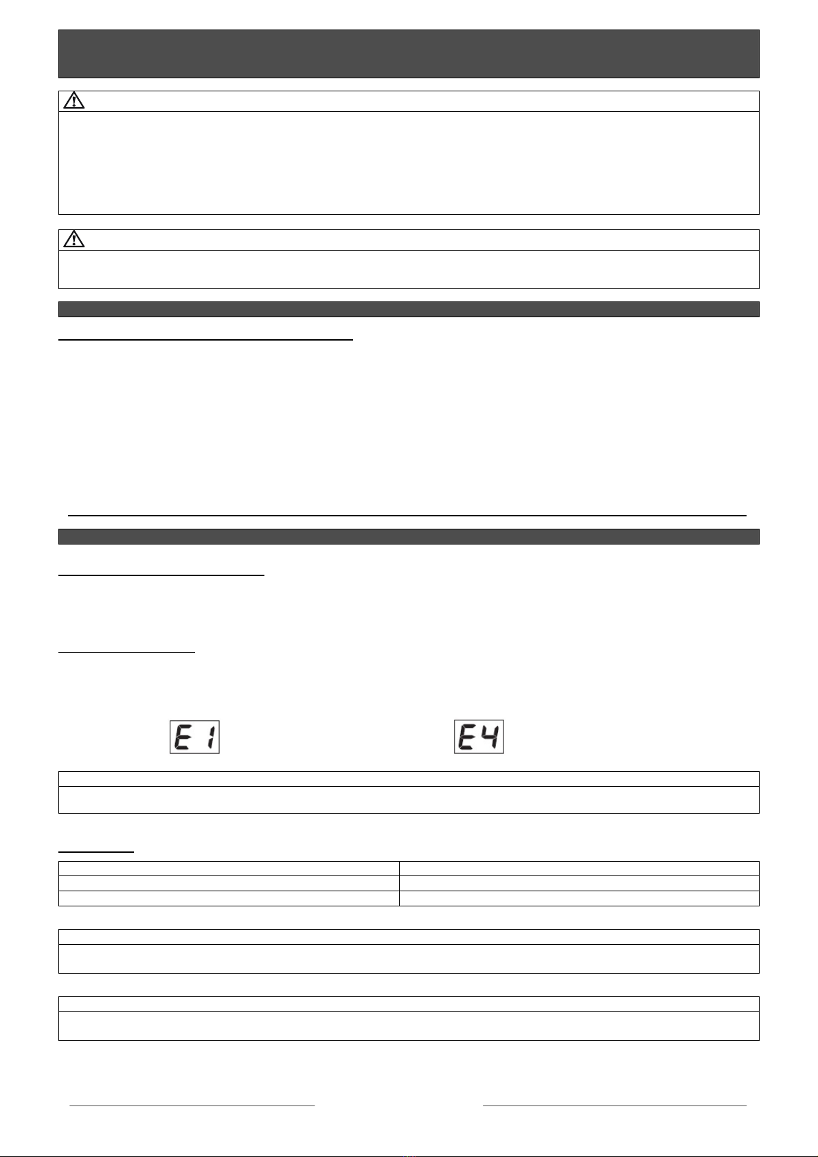
If, when the control unit is turned ON, one of the sensors turns out to be inoperative or not connected, an audio signal will sound
for 3 sec.
If more than one sensor is inoperative, the number of the faulty sensors will be alternatively displayed on the main control unit.
SENSOR 1 => inoperative SENSOR 4 => inoperative
NOTE
One single faulty sensor alters the correct functioning of the whole parking system.
5.3 OTHERS
POSSIBLE CAUSE SOLUTION
Ice on sensors. Clean the sensors.
Back part of sensors in contact with frame. Create a separation between the sensors and the vehicle.
NOTE
In case of heavy rain or snow the parking system might give an audible alert even if no obstacles are present: this does not
necessarily indicate that the parking system is defective.
NOTE
If, once activation is confirmed, the buzzer keeps beeping and no obstacle is in front of the vehicle, the parking system is
defective: contact your SUZUKI dealer.

SUZUKI GENUINE ACCESSORIES
English_I-M 990E0-54P56-000 rev01 03/2015
5
6. DETECTION ZONES
Detection zones are indicated as “F1” and “F2” and the detection zone closest to the obstacle “FC”. The stage-by-stage sound
alert will vary according to the detection zone.
The STOP zone is the minimum distance detected between an obstacle and the sensor. In this case the warning tone is solid.
ZONE DISTANCE
FC 35 cm
F1 60 cm
F2 85 cm
7. WARRANTY CONDITIONS
This product is guaranteed to be free from manufacturing defects for a period of 24 months from the purchase date validated by
the receipt or invoice (in compliance with Warranty Directive 1999/44/CE (L.D. N24 dated 02/02/2002); if these documents are
not available, warranty will start from the manufacturing date stated on and inside the product itself.
Warranty only covers the repairing or replacement of the parts showing manufacturing defects; direct labour, transport and any
other charges are excluded. The warranty does not apply in case of malfunctioning caused by: negligence, improper installation,
tampering and improper use of the system and its application is entirely at the manufacturer’s discretion. In case of any warranty
request please contact your SUZUKI dealer.
The above is the only guarantee prescription and the buyer shall not have the right to ask for cancellation of the contract,
compensation for damage and/or price reduction.
8. TECHNICAL SPECIFICATIONS
9. WASTE ELECTRICAL AND ELECTRONIC EQUIPMENT (WEEE) DIRECTIVE
The present device does not fall within the scope of Directive 2002/96/EC on Waste Electrical and Electronic Equipment
(WEEE) as specified in art. 2.1 of L.D. no. 151 of 25/07/2005.
Supply voltage 9 => 30 Vdc
Current consumption - system ON 200mA max.
Operating temperature range -30°C => +70°C
Ultrasonic frequency 40 kHz

SUZUKI GENUINE ACCESSORIES
English_I-M 990E0-54P56-000 rev01 03/2015
6
10. PROGRAMMING
CAUTION
Only expert users should modify the settings to avoid malfunctions of the parking system.
The display will indicate:
FS: Factory Settings => Factory default adjustments.
CS: Custom Settings => User-chosen adjustments.
To enter in programming mode, proceed as follows:
Press one of the two buttons on the control unit and keep it pressed for at least 2 seconds:
the system will activate and enter in programming mode.
Press the LEFT button to go back to the previous parameter.
Press the RIGHT button to move up to the next parameter.
When the parameter you want to modify is displayed, press one of the buttons and keep it pressed
until the display starts to blink: at this point the parameter can be modified.
Press the LEFT button to decrease the parameter value.
Press the RIGHT button to increase the parameter value.
Press one of the two buttons on the control unit and keep it pressed for at least 2 seconds to register the value.
The display will stop blinking and the selected parameter will be displayed.
If no button is pressed within10 seconds, the system will exit the programming mode.
NOTE
To reset factory settings (FS), simultaneously press the 2 buttons on the control unit and keep them pressed for more than 2
seconds.

SUZUKI GENUINE ACCESSORIES
English_I-M 990E0-54P56-000 rev01 03/2015
7
11. SETTING OF PARAMETERS
CAUTION
The system is factory configured, modify default settings only if strictly necessary!
Par. Parameters Selectable Settings Factory Settings
01 Volume of buzzer 0, 1, 2 (Ref.1) 2
02 Detection range - Central sensors 50 - 95 cm 90
03 Detection range - Outer sensors 50 - 95 cm 50
06 STOP zone - Central sensors 35 - 50 cm 50
07 STOP zone - Outer sensors 35 - 50 cm 35
11 Number of speed signal pulses 1 - 99 2
12 Delay of sensors deactivation 0 or
10 - 60 sec. (Ref.2) 00
15 Service display (testing) 0, 1, 3 (Ref.3) 0
16 Continuous detection - zones F1 and F2 0, 1 (Ref.4) 1
17 Sensitivity 1, 2, 3 (Ref.5) 1
Ref.1: 0 = OFF
1 = Low
2 = High
Ref.2: By setting “00” => the system is activated every time ignition is turned ON.
To disable => press the button on the LED receptacle.
To turn it back ON => press the same button again.
Ref.3: 0 = OFF
1 = Distance from closest obstacle.
3 = Vehicle approx. speed (km/h, refer to parameter 11 to program).
Ref.4: 0 = OFF
1 = ON
Ref.5: 1 = Low
2 = Medium
3 = High
12. TESTING
a. To enter in programming mode, press and hold for at least 2 seconds one of the two buttons on the control unit (4).
b. Select parameter “15” (see “Setting of parameters”).
c. Press and hold one of the two buttons and select the test: “1” to test sensors or “3” to detect speed.
d. Press and hold one of the two buttons; the display will show “--”.
e. Test the sensors; the system will indicate the actual distance.
f. Reset parameter to “00”.
g. When testing is completed, press and hold one of the two buttons until the previously selected parameter (15) is displayed.
h. The system will automatically exit programming mode 10 seconds after the button has been pressed.

SUZUKI GENUINE ACCESSORIES
English_I-M 990E0-54P56-000 rev01 03/2015
8
13. INSTALLATION -
V
ITAR
A
(LY)
OPTIONAL
CAUTION
Drill through the factory markings on the inside of the bumper with the following drill bits:
•Central Sensors: 18mm
•Outer Sensors: 26mm
C
REMOVE
BUMPER
Bum
p
er inside view
A
B
18-26mm
Bum
p
er inside view
OPTIONAL

SUZUKI GENUINE ACCESSORIES
English_I-M 990E0-54P56-000 rev01 03/2015
9
NOTE
Brackets (6): Clean thoroughly the plastic brackets and around the holes, apply “PRIMER” (12), let dry for at least 1 minute
and then proceed as illustrated below.
NOTE
Brackets (9): Snap-in type brackets which do not require adhesive pads. Snap the brackets in the holes from the OUTSIDE of
the bumper in the appropriate direction as illustrated below.
D
Bum
p
er inside view
E
Bum
p
er inside view
Front View Rear View
TOP
Bum
p
er inside view

SUZUKI GENUINE ACCESSORIES
English_I-M 990E0-54P56-000 rev01 03/2015
10
IMPORTANT
Sensor 1: shortest cable
Sensor 4: longest cable
41
32
CAUTION
Insert the sensors in brackets (6) and (9) in the appropriate direction as illustrated below.
NOTE
Check length of cables before proceeding with final positioning of accessories.
G
F
Bum
p
er inside view

SUZUKI GENUINE ACCESSORIES
English_I-M 990E0-54P56-000 rev01 03/2015
11
CABLE ROUTING
NOTE
Route wiring through the door sill to the right front inner wheelhouse.
H Inside grommet:
21mm
Outer grommet:
18mm
RHS
RHS Inner wheelhouse RHS
J
i
K
Use the supplied clips to hold the cables in place.
L

SUZUKI GENUINE ACCESSORIES
English_I-M 990E0-54P56-000 rev01 03/2015
12
CONTROL UNIT - BUZZER and PUSH-BUTTON WITH LED INDICATOR
NOTE
BUZZER and PUSH-BUTTON with LED indicator can be positioned according to customer request. Make sure the button can be
readily seen and easily reached.
M RH side RH side
Table of contents
Other Suzuki Automobile Accessories manuals

Suzuki
Suzuki 990E0-64J07-000 User manual

Suzuki
Suzuki 99115-63T10-K01 User manual

Suzuki
Suzuki 990E0-54P56-010 User manual

Suzuki
Suzuki 99177-78R00 User manual

Suzuki
Suzuki Towbar Wiring Kit 13P User manual

Suzuki
Suzuki VZ800L0 User manual

Suzuki
Suzuki 99178-78R00 User manual

Suzuki
Suzuki 99000-99074-68N User manual

Suzuki
Suzuki 990E0-78R53-000 User manual
Popular Automobile Accessories manuals by other brands

ULTIMATE SPEED
ULTIMATE SPEED 279746 Assembly and Safety Advice

SSV Works
SSV Works DF-F65 manual

ULTIMATE SPEED
ULTIMATE SPEED CARBON Assembly and Safety Advice

Witter
Witter F174 Fitting instructions

WeatherTech
WeatherTech No-Drill installation instructions

TAUBENREUTHER
TAUBENREUTHER 1-336050 Installation instruction