•WARNING: Before servicing any installed valve, to avoid personal
injury, you must
• depressurize the system
• cycle the valve
• purge the system to remove any residual system media left in
the valve
NOTE: It is important to refer to the exploded view drawing while
following the maintenance instructions.
DISASSEMBLY
End Screws:
1. Remove end screws from valve body.
2. Discard the backup rings, carrier o-rings, seat spring, seat carrier
assemblies, end screw seals, and seat carrier guides.
Ball & Stem:
3. Remove the set screw (not pictured) in handle and remove handle.
Note the position of the handle for reassembly.
MS-CRD-0266
Rev -
November, 2019
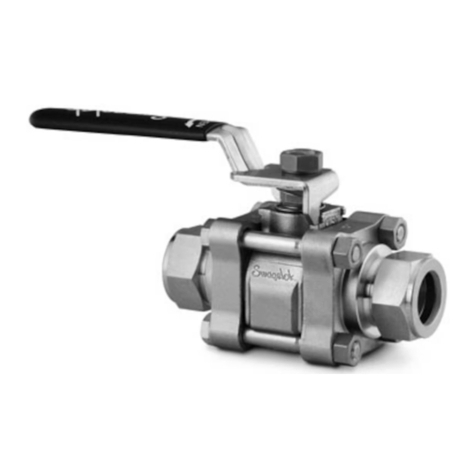
“83DXL” SERIES BALL VALVE
MAINTENANCE INSTRUCTIONS
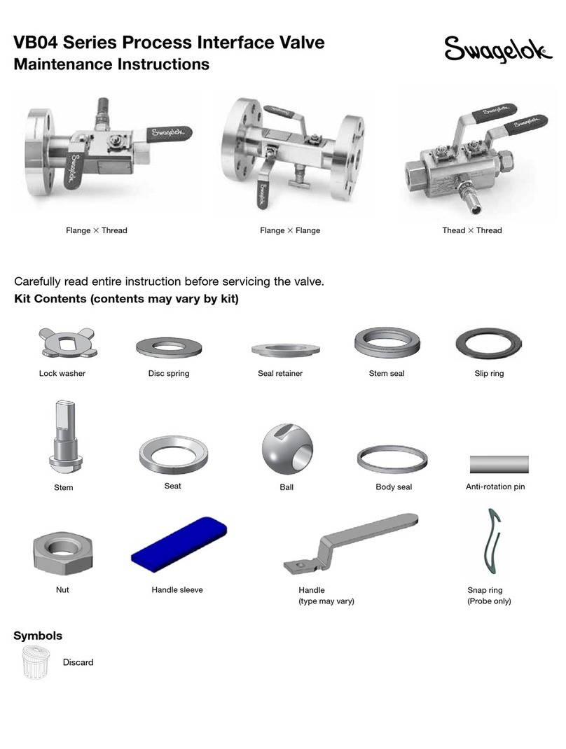
Kit Contents:
Ball Stem
Trunnion Bearings (2) O-Rings (3)
Seat Carrier Back-up Rings (4) Seat Carrier Assemblies (2)
Seat Springs (12) End Screw Seals (2)
Stem Bearing Stem Back-up Rings (3)
Lubricant Instruction Sheet
Seat Carrier Guides (2) Material Safety Data Sheet
4. Remove the ball assembly through the bottom of the valve body. Note
the position of the ball orices for reassembly. (It may be necessary
to place an object into the ball orice and press down to release the
ball. Discard the ball.
5. Press down on the top of the stem and remove through the bottom of
valve body.
6. Remove and discard the stem o-rings, back-up rings, stem bearing,
and stem.
7. Carefully, remove all lubricants and contaminants from inside the valve
body.
REASSEMBLY
End Screws:
1. Clean all lubricant or contaminants from end screws (reusable).
2. Apply a moderate coating of MS-LT-WL7 lubricant to the seat carrier
back-up rings, carrier O-rings, and end screw seals.
3. Place seat springs onto the shank of the seat carrier assembly.
4. Place other components onto the shank of the seat carrier assembly
in the following order:
1. Metal seat carrier guide
2. One plastic back-up ring
3. Seat carrier o-ring
4. One plastic back-up ring
5. Insert the seat carrier assemblies into the end screws. Place an end
screw seal over each seat carrier assembly and position on the end
screws.
End screw assemblies are now complete.
Ball & Stem:
6. STEM Preparation:
•Apply a moderate coating of MS-LT-WL7 lubricant to the stem O-ring.
•With the chamfer side up, place the stem bearing on the stem.
•Place the O-ring, PTFE back-up ring, and the PEEK back-up ring
(concave up) in the lower stem groove.
•Place the remaining PTFE back-up ring in the upper stem groove.
BALL Preparation:
•Place the upper and lower trunnion bearings into the ball grooves.
Stem assembly is now complete.
7. Insert the stem through the bottom of the valve body and gently press
the stem up into position using a blunt instrument. Gently press upwards
until the stem reaches its uppermost position against the body bore.
Take care not to score the inside walls of the body bore, or to clip the
stemo-rings duringinstallation.Thestemholeshouldbeperpendicular
to the end screw holes to allow proper alignment with the handle.
8. Place the handle over the stem. The handle should be installed by aligning
the arrow on the top of the stem with the arrow on the underside of
the handle. Align the handle set screw hole with the stem hole. Place
the set screw in handle and tighten.
9. Lightly lubricate the new ball and the trunnion bearings with MS-LT-WL7
lubricant and insert (tang up) through bottom of valve body. Press
upward until the ball tang engages the stem slot. To test; turn handle,
if ball rotates tang is engaged.
Note: Be sure the open orice is positioned towards the handle front.
10.Turn the valve handle 90 degrees from the inlet to avoid damage
to the seats while torqueing the end screws.
11.Insert the end screw assemblies and torque to 500 in.·lb each.
(56.5N·m).
