manuals.online logo
Brands
  1. Home
  2. •
  3. Brands
  4. •
  5. Swagelok
  6. •
  7. Control Unit
  8. •
  9. Swagelok AFS Series Operating instructions

Swagelok AFS Series Operating instructions

MS-CRD-AFS
MS-CRD-AFS
R1 06-05-CP
Swagelok
®
Alternative Fuel Service (AFS) Ball Valve
Service Instructions
Seat Seal Kit
Backup ring (2)
Seat spring (2)
Seat O-ring (2)
Lubricant
Seat (2)
Gasket (2)
Tools Required
Optional: Small nonmetallic pick
Stem
and Seat Seal Kit
Lubricant

WARNING
BEFORE REMOVING A
VALVE
FROM THE SYSTEM FOR SERVICE, YOU MUST
• depressurize system
•
cycle the
valve
• purge the
valve.
Stem thrust
washer
Stem guide
ring (2)
Stem backup
ring
Stem O-ring
P
acking bolt
g
asket
Backup ring (2)
Seat spring (2)
Seat O-ring (2)
Seat (2)
Gasket (2)
Part
Tool
Size
Valve body
Bench vise
—
Open-end wrench
1 1/2 in.
End screw
Open-end wrench
1 3/16 in. (30 mm)
Crow's foot
Socket
Packing bolt
Socket
13/16 in.
Packing bolt,
end screw
Torque wrench
600 to 700 in.·lb
(68 to 79.1 N·m)
(692 to 806 cm·kg)
2
MS-CRD-AFS
MS-CRD-AFS
R1 06-05-CP
Seat
End screw gasket
Seat backup ring
Seat spring
Seat O-ring
Seat gland
End screw
Ball
Handle
Packing bolt
Packing bolt gasket
Stem backup ring
Stem O-ring
Stem
Set screw
Guide ring
Stem thrust washer
Panel nut
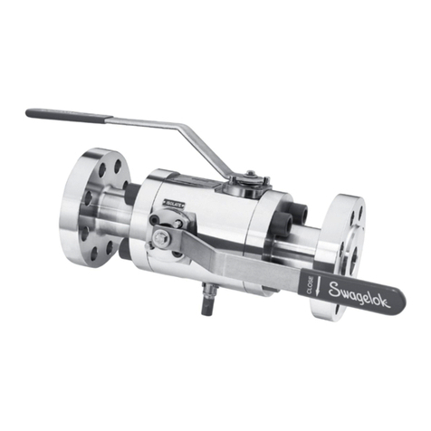
Refer to the Fig. 1 while following these instructions.
Complete the maintenance on one end screw assembly
before proceeding to the other end screw assembly.
Disassembly
Seat Seal
Disassembly
1. Remove the
valve
from the system. Actuate the
handle
to the OPEN position.
2. Place the
valve
in a vise or use a 1 1/2 in. wrench to
hold the body.
3. Loosen and remove one
end screw assembly
from
end screw assembly from end screw assembly
the body.
4. Remove the
seat
,
seat O-ring
,
seat
backup ring
,
seat
gland
,
seat spring,
and
end screw gasket
from the
end screw
. (The use of a small, non-
metallic pick or similar tool is optional.)
Discard all
removed components except the
seat
gland
and
end screw
. Proceed to
Reassembly
if not replacing
Reassembly if not replacing Reassembly
stem seal components.
Stem Seal Disassembly
5. Actuate the
handle
to the CLOSED position.
6. Remove the
handle set screw
and
handle
and set
aside.
7. Remove the
ball
and set aside.
8. Loosen and remove the
packing bolt
and
packing
bolt gasket
from
valve body
. Remove the
packing
bolt gasket
from the
packing bolt
and discard the
packing bolt
gasket
.
9. Remove the stem assembly from the packing bolt.
10. Remove the
stem guide rings
,
stem backup ring
,
stem O-ring
, and
stem
thrust washer
from
stem
and discard.
Reassembly
1.
Clean all lubricant and contaminants from the
sea
t
gland
,
end screw, packing bolt,
stem,
a
nd
ball
.
Stem
Seal
Reassembly
2. Apply a thin film of the pro
vided
lubricant
to the
stem thrust w
asher
,
stem O-ring
,
stem backup
ring
, and
stem guide rings
.
3. Place the
stem thrust w
asher
,
stem O-ring
,
stem
backup ring
, and
stem guide rings
onto the
stem
.
Note: The chamfer on the stem back
up ring shoul
d
point up.
4. Insert the stem as
sembly into the
packing bolt
.
Note: Be careful not to pi
nch the stem assembly
components when inserting into the packin
g bolt.
5. Place the
packing bolt gasket
on the
packing
bolt
.
6. Place
packing bolt
in
valve body
and torque to
valve body and torque to valve body
600
to 700 in.·lb (68 to 79.1 N·m) (692 to 806 cm·kg).
7. Lubrica
te the
ball
with the supplied
lubricant
. Place
the ball into the bo
dy by aligning the ball slot with
the stem ta
ng.
Note: Verify the
ball
and
stem
are alig
ned correctly
by a
ctuating the valve.
Seat Seal
Reassembly
8. Apply a thin film of the pro
vided
lubricant
to the
seat
,
seat O-ring
seat O-ring
,
backup ring
, and
seat
gland
.
9
. Insert the
seat spring, seat
seat spring, seat
gland
,
backup ring
,
seat O-ring
, and
seat
seat
into the end screw as shown.
10
. Place the
end screw
end screw
gasket
on the
sealing
surface
of the end screw.
of the end screw.
11
. Thread the
end screw assembly
end screw assembly
into the body.
end screw assembly into the body. end screw assembly
Torque the end screw to 600 to 700 in.·lb (68 to
79.1 N·m) (692 to 806 cm·kg).
12. Repeat the procedure on the other end screw
assembly, if required.
13. Replace handle and thread set screw into the
handle. Torqu
e the set scr
e the set scr
ew to 80
to 110 in.·l
bs
(9.0 to 12.4 N·m) (92.1 to 123 cm·kg).
14. Test the
valve
for proper operation and leak-tight
integrity.
Fig. 1
3
MS-CRD-AFS
MS-CRD-AFS
R1 06-05-CP
4. Turn the
handle
upside down
and place the
top
bracket
on the base of the handle aligning the
cut
out
in the bracket with the
notch
on the handle. Fig.
4
5. Holding the
top
bracket
against the
handle
, turn
the handle
right side up
and place the
handle
on
the valve stem, aligning the
stem flat
and
set
screw
. Fig. 2.
Note: The
padlock hole
in the top bracket must
align with either one of the
padlock holes
in the
bottom bracket for proper operation
(Fig 5).
If the
holes do not align properly, remove the handle and
repeat steps 3 through 5.
6. Thread the
set screw
into the
handle
and tighten to
80 to 110 in.·lb (9.0 to 12.4 N·m) (92 to 127 cm·kg).
7. Test the
valve
for proper operation.
1. Loosen the
set screw
in the handle. Fig. 2
2.
Remove the
handle
.
Locking Bracket Kit
Bottom bracket
Top bracket
Tools Required
Set screw
Handle
Stem flat
Fig. 2
Top
bracket
Cut out
Notch
Cut out
Fig. 4
Alignment
Alignment
of padlock
of padlock
holes
holes
Fig. 5
Fig. 5
3. Place the
bottom bracket
on the valve aligning the
cut out
in the bracket with the
notch
on the valve.
Fig. 3.
Notch
Cut out
Fig.
3
Bottom
Bottom
bracket
bracket
Torque wrench
Hex key
5/32 in.
Hex
bit
5/32 in.
80 to 110 in.·lb
(9.0 to 12.4 N·m)
(92 to 127 cm·kg)
4
MS-CRD-AFS
MS-CRD-AFS
R1 06-05-CP
Swagelok—TM Swagelok Company
© 2004, 2005 Swagelok Company
Refer to Fig. 6 during these instructions.
1. Loosen the
set screw
in the handle .
2.
Remove the
handle
.
3. Place the new
handle
on the valve stem, aligning
the
stem flat
and
set screw
.
4. Thread the
set screw
into the handle and tighten to
80 to 110 in.·lb (9.0 to 12.4 N·m) (92 to 127 cm·kg).
5. Test the
valve
for proper operation.
Nylon Handle Kit
Tools Required
Set screw
Handle
Stem flat
Fig.
Fig.
6
Handle
Handle
Set screw
Set screw
Torque Wrench
Hex key
5/32 in.
Hex
bit
5/32 in.
80 to 110 in.·lb
(9.0 to 12.4 N·m)
(92 to 127 cm·kg)

Other Swagelok Control Unit manuals

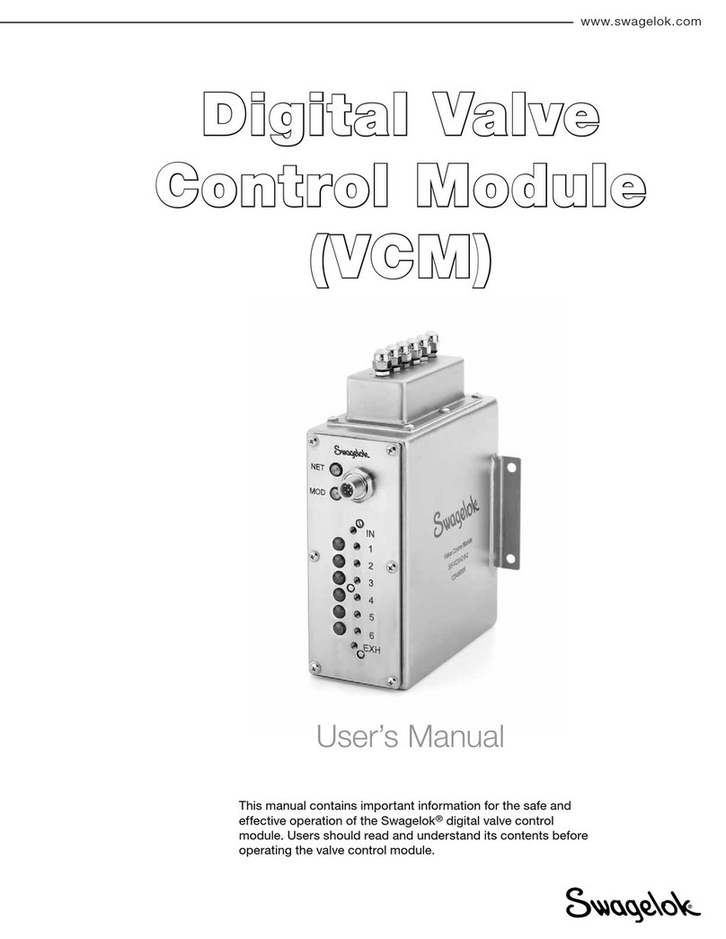
Swagelok VCM User manual

Swagelok

Swagelok VCM User manual

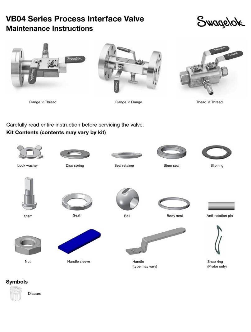
Swagelok VB04 Series Technical specifications

Swagelok

Swagelok VB04 Series Technical specifications

Swagelok VB03 Series User manual

Swagelok

Swagelok VB03 Series User manual

Swagelok 60 Series User manual

Swagelok

Swagelok 60 Series User manual

Swagelok SK Series Operating instructions

Swagelok

Swagelok SK Series Operating instructions

Swagelok S60 Series User manual

Swagelok

Swagelok S60 Series User manual

Swagelok RHPS Series User manual

Swagelok

Swagelok RHPS Series User manual

Swagelok RHPS Series User manual

Swagelok

Swagelok RHPS Series User manual

Swagelok IPT Series User manual

Swagelok

Swagelok IPT Series User manual

Swagelok XS Series Operating instructions

Swagelok

Swagelok XS Series Operating instructions

Swagelok 60 Series User manual

Swagelok

Swagelok 60 Series User manual

Swagelok DF Series Operating instructions

Swagelok

Swagelok DF Series Operating instructions

Swagelok IPT Series User manual

Swagelok

Swagelok IPT Series User manual

Swagelok IPT Series Operating instructions

Swagelok

Swagelok IPT Series Operating instructions

Swagelok S60P Steam Series Technical specifications

Swagelok

Swagelok S60P Steam Series Technical specifications

Swagelok 83DXL Series Operating and maintenance instructions

Swagelok

Swagelok 83DXL Series Operating and maintenance instructions

Popular Control Unit manuals by other brands

CLA-VAL 58-01 Installation, operation and maintenance

CLA-VAL

CLA-VAL 58-01 Installation, operation and maintenance

RDZ WI-SA Technical manual

RDZ

RDZ WI-SA Technical manual

Bang & Olufsen STB-C Mounting instruction

Bang & Olufsen

Bang & Olufsen STB-C Mounting instruction

Edwards SCU-XL800 instruction manual

Edwards

Edwards SCU-XL800 instruction manual

Jetter JX3-THI2-TC-EI user manual

Jetter

Jetter JX3-THI2-TC-EI user manual

MD mXion PSD user manual

MD

MD mXion PSD user manual

National Instruments NI 9402 Getting started guide

National Instruments

National Instruments NI 9402 Getting started guide

Eaton PXS24 Series Technical manual

Eaton

Eaton PXS24 Series Technical manual

Allen-Bradley 1792-IB16 Series B installation instructions

Allen-Bradley

Allen-Bradley 1792-IB16 Series B installation instructions

monolith ZEUS003 INSTRUCTION FOR THE ASSEMBLAGE

monolith

monolith ZEUS003 INSTRUCTION FOR THE ASSEMBLAGE

Siemens SIRIUS 3RA2916-1A operating instructions

Siemens

Siemens SIRIUS 3RA2916-1A operating instructions

Vapotherm Oxygen Assist Module Instructions for use

Vapotherm

Vapotherm Oxygen Assist Module Instructions for use

Siemens VVF Series Mounting instructions

Siemens

Siemens VVF Series Mounting instructions

Belanger Bias-T owner's manual

Belanger

Belanger Bias-T owner's manual

Genebre 2113 manual

Genebre

Genebre 2113 manual

Honeywell SILENT KNIGHT SK-FML installation instructions

Honeywell

Honeywell SILENT KNIGHT SK-FML installation instructions

Beamz C2-IEC instruction manual

Beamz

Beamz C2-IEC instruction manual

CO.SI.ME EFDC Series Installation and maintenance instructions

CO.SI.ME

CO.SI.ME EFDC Series Installation and maintenance instructions

manuals.online logo
manuals.online logoBrands
  • About & Mission
  • Contact us
  • Privacy Policy
  • Terms and Conditions

Copyright 2025 Manuals.Online. All Rights Reserved.