Swecoin TTP 5250 User manual

TTP 5200/5250 Kiosk Printer
Sub-system
Service Manual
Publ. No. 101469, Ed. A

TTP 52x0 Series Kiosk Printer Sub-system — Service Manual December 2001
Related manuals
TTP 5200/5250 Getting Started (01451-000)
TTP 5100/5200/5250 Operating Instructions (01434-000)
TTP 5200/5250 Installation Manual (01436-000)
TTP 5200/5250 Technical Specification (01441-000)
TTP 5200/5250 Service Manual (101469)
This is a publication of Swecoin AB
Box 322, SE-192 30 Sollentuna, Sweden
Phone +46 8 623 45 60
Fax +46 8 594 709 89
E-mail techsupport@swecoin.se
sales@swecoin.se
Web site
http://www.swecoin.se
© Swecoin AB 1997, 2001
All rights reserved. Reproduction in whole or in parts is
prohibited without written consent of the copyright owner. We
have taken great care to ensure that the information in this
manual is correct and complete. However, if you discover any
errors or omissions, or if you wish to make suggestions for
improvements, you are welcome to send your comments to
us. Swecoin AB disclaims any liability resulting from the use
of this information and reserves the right to make changes
without notice.
Edition A, December 2001
Printed in Sweden

December 2001 TTP 52x0 Series Kiosk Printer — Service Manual 1
Contents
1Introduction................................................................................................................ 3
1.1 About this manual...................................................................................... 3
1.2 Updating .................................................................................................... 3
1.3 Safety precautions ..................................................................................... 3
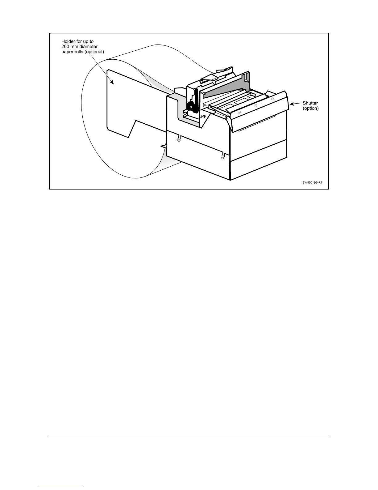
1.4 The TTP 52x0 products ............................................................................. 3
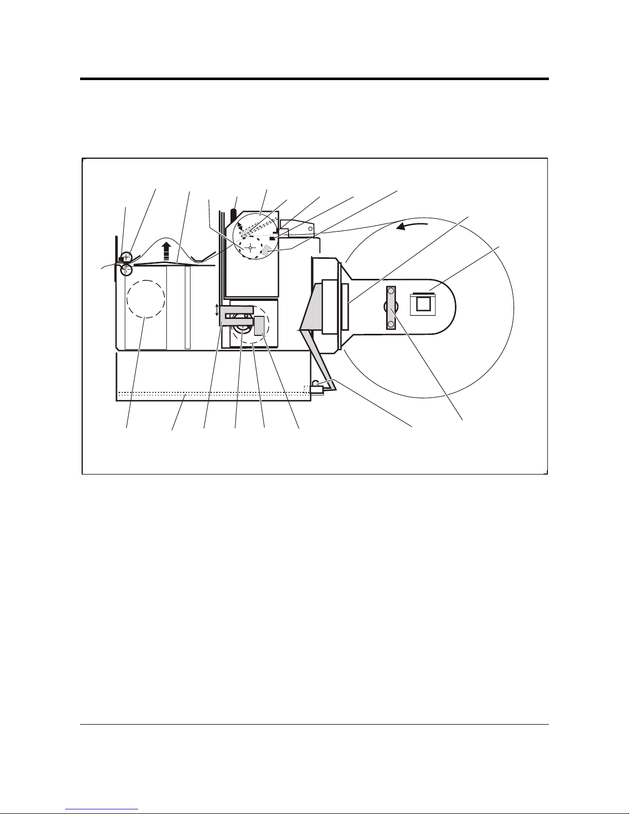
2Functional description .............................................................................................. 6
2.1 Paper handling........................................................................................... 7
2.2 Paper near-end detection .......................................................................... 8
2.3 Paper jam detection................................................................................... 8
2.4 Cutting ....................................................................................................... 9
2.5 Printhead-up detection............................................................................... 9
2.6 Electronics ............................................................................................... 10
2.6.1 Microprocessor system ............................................................... 10
2.6.2 Static RAM .................................................................................. 10
2.6.3 Flash PROM................................................................................ 10
2.6.4 Printing ........................................................................................ 10
2.6.5 Cutting ......................................................................................... 10
2.6.6 Communications interface........................................................... 10
2.6.7 Power supply............................................................................... 11
3Maintenance............................................................................................................. 12
3.1 Fault finding ............................................................................................. 12
3.2 Hex dump ................................................................................................ 13
3.3 Parts removal and replacement............................................................... 14
3.3.1 Control board connectors............................................................ 14
3.3.2 Separating the upper and lower chassis modules ...................... 14
3.3.3 TTP 5200 control board .............................................................. 14
3.3.4 TTP 5250 control board .............................................................. 15
3.3.5 Print module ................................................................................ 16
3.3.6 Cutter module.............................................................................. 17
3.3.7 Presenter module........................................................................ 19
3.3.8 Printhead ..................................................................................... 20
4Spare parts ............................................................................................................... 21
4.1 Printer complete ...................................................................................... 22
4.1.1 Final assembly ............................................................................ 22
4.1.2 Print module ................................................................................ 23
4.1.3 Presenter module........................................................................ 24
4.1.4 Cutter assembly .......................................................................... 26
4.1.5 Roll holder assembly, Standard .................................................. 28
4.1.6 PCB cover assy. Standard .......................................................... 29
4.1.7 PCB cover assy. Closed (option) ................................................ 30

TTP 52x0 Series Kiosk Printer Sub-system — Service Manual December 20012
4.2 Options .................................................................................................... 31
4.2.1 Shutter......................................................................................... 31
4.2.2 Parallel and serial adapters......................................................... 31
4.2.3 Roll holder assy, 200 mm (8") behind ......................................... 32
4.2.4 Drop in roll holder assy, 150 mm (6") behind .............................. 34
4.2.5 Roll holder Option 250mm (10").................................................. 35
5Drawings .................................................................................................................. 39
5.1 Versions................................................................................................... 48
5.2 Revisions ................................................................................................. 49
5.2.1 PCA Revision E........................................................................... 49
5.2.2 PCA Revision F ........................................................................... 49
5.2.3 PCA Revision G .......................................................................... 50
5.2.4 Printed Circuit Board (PCB) Revision D..................................... 50

December 2001 TTP 52x0 Series Kiosk Printer— Service Manual 3
1 INTRODUCTION
1.1 About this manual
This manual describes the Swecoin TTP 52x0 Series kiosk printers, their function,
maintenance instructions, spare parts, etc. For information about the TTP 5000 and
TTP 5100, please use the "TTP 5000 Series Service Manual" 00803-000.
1.2 Updating
This manual will be updated as, from time to time, printer functions and features may be
added or amended. You will always find the latest edition on our web site
(www.swecoin.se). You can order printed copies of the current manual by e-mail, fax, or
phone.
If you require functions not found in the manual edition at your disposal, you are welcome
to consult one of our representatives for information.
1.3 Safety precautions
Handling the printer in a safe way requires that you keep your fingers away from the
cutting mechanism when the power is switched ON.
1.4 The TTP 52x0 products
Two basic models are available: TTP 5200 and TTP 5250. The 5200 requires dual supply
voltage; 5V and 24V, while the 5250 only requires 24V. Apart from this the models are
exactly the same.
Each model is further divided into types representing the paper widths 60, 80, and
112 mm. Each type can also be divided into versions depending on installed options.

TTP 52x0 Series Kiosk Printer — Service Manual December 20014
A unique, Swecoin patented, feature of the TTP-series of printers is that they can retain
the document inside until both the printing and the cut-off operations are completed.
A number of sensors monitor the printer operation.
Refer to the applicable Technical Specification and Installation Manual for further
information on technical data, printer functions, etc.
Form-feed
button
Paper
release lever
Print module
Cutter module
Presenter module
Document
exit
SW95018F-R2
Paper roll
support shaft
Power indicators Control board
Printhead open
Handle
Figure 1. Basic TTP 52x0 printer

December 2001 TTP 52x0 Series Kiosk Printer— Service Manual
5
Figure 2. TTP 52x0 Series equipped with optional large roll holder and shutter.

TTP 52x0 Series Kiosk Printer — Service Manual December 2001
6
2 FUNCTIONAL DESCRIPTION
The printer chassis is made up of a lower module containing the printer control board and
an upper module containing the mechanical functions.
Paper
release
lever Print-
head
Paper
guide
bar
Form-feed
button
Cutter
motor
Cam
wheel
Cutting
blade
Cutter-home
sensor
Control
board
Deflection
ribs
Presenter
motor
Presenter
sensor
Paper-end
& TOF
sensor
Paper-near-end
sensor (actuated
when 2-4 m remains)
Platen
Presenter
feed rolls
Printhead-lifted
sensor
Power
indicators
SW95012C-R2
Paper-feed
motor
Optional serial or
parallel interface
adaptor cable
Figure 3. Printer design
The printer has three motors controlled by the control board firmware. All sensors are
reflector-type opto-sensors, except the printhead-up and cutter-home sensors that are
micro switches.

December 2001 TTP 52x0 Series Kiosk Printer— Service Manual
7
2.1 Paper handling
The print module has a stepper-motor that drives a platen. The thermal printhead presses
against the platen with the temperature sensitive paper in-between. The platen pulls the
paper from the supply roll and feeds the paper through the cutter module and up to a
couple of feed rollers in the presenter module. The presenter motor (DC-motor) drives the
rollers.
During the printing procedure, the firmware runs the presenter motor slowly until the
presenter sensor detects the leading paper edge. The presenter feed rollers then stops
and holds the top of the document. Deflection ribs in the presenter module assist in
forming a document loop within the printer when the firmware postpones the presentation
until printing and cutting is completed. The presenter motor will then present the
document to the customer. If so selected by the application program, the presenter feed
rollers can be set at continuous feed-through during printing, for example, when very long
documents are being printed.
The presenter sensor also detects when the trailing document edge leaves the exit slot.
The combined paper-end and TOF sensor is actuated by light reflection against the back
of the paper. If the light reflection disappears, but returns within a specified number of
paper-feed motor steps, this means that a pre-printed black mark is detected. If the light
does not return before this number of motor steps has been effected, this will be
interpreted as paper end.

TTP 52x0 Series Kiosk Printer — Service Manual December 2001
8
2.2 Paper near-end detection
All Swecoin roll holders have an optical reflection sensor that becomes actuated when
there is about 3 m paper left (see Figure 3). This is the paper near end sensor.
In addition, the optional paper roll holders for larger paper rolls have an adjustable paper
level sensor (see Figure 4) that can be used, for example, to decide whether or not the
remaining paper will last during a weekend, thus called “Weekend sensor”.
The paper end & TOF sensor (reflector sensor) inhibits printing if there is no paper at all in
the printer module.
Optical paper level sensor, “weekend sensor”.
Adjustment range: 80 ±20 mm
equal to approximately
30—150 m remaining paper.
Lock screw
Optical paper-near-end
sensor.
Activated when
2–4 m remains.
SW95003A-R1
Figure 4. Paper sensor roll holder for 200-mm diameter rolls (optional)
2.3 Paper jam detection
The application program knows the length of each document. If the presenter sensor does
not detect the leading edge of a document when expected, this will be interpreted as if
paper jam has occurred. Paper jam error will also be signaled if the presenter sensor
detects paper in unexpected situations.

December 2001 TTP 52x0 Series Kiosk Printer— Service Manual 9
2.4 Cutting
The cutter module moves the cutting blade down (cutting), and then it returns up again to
the home position. A DC-motor and a crank mechanism drive the cutter. A sensor detects
when the blade reaches the home position.
A vertical leaf spring (not shown in the above figure) aids in keeping the free end of the
movable knife blade pressed against the fixed cutting edge.
WARNING!
RISK OF INJURY! Depending on the position of the crank mechanism, the cutting knife
may start moving when the printer is switched ON. KEEP HANDS AWAY WHEN
SWITCHING ON THE PRINTER.
2.5 Printhead-up detection
Lowering the paper release lever separates the printhead from the platen and actuates
the printhead-up micro-switch sensor. This sets a status bit in the status message.
Printing is interrupted as long as the printhead is lifted.
Lowering the paper release lever is also part of the procedure for setting the printer in a
HEX dump mode for logging the data transfer between the host and the printer. See page
13.
CAUTION! — If the printer is not going to be used for a week or more, disengage the
printhead from the platen by lowering the paper release lever. Both the printhead and the
platen can otherwise be deformed.

TTP 52x0 Series Kiosk Printer — Service Manual December 20011
0
2.6 Electronics
Also see logic diagrams in Chapter 4.3.3.
2.6.1 Microprocessor system
The control board is equipped with an 80C320 microprocessor. The TTP 52x0-printers
meet the EMC directives for CE marking.
2.6.2 Static RAM
The control board has 256 Kbyte static RAM used for buffering of graphics data during
printing. It allows full landscape printing (210 mm).
2.6.3 Flash PROM
A Flash PROM on the control board holds the printer firmware, fonts, parameter settings,
etc. The flash PROM allows online downloading of its contents.
2.6.4 Printing
The control board controls the printing. It has four fonts installed, and possibility to hold
four more custom designed fonts. Each font can be printed in it’s standard size, double
width, double height and quadruple size, in both portrait and landscape modes, as black
on white background or the reverse, and with or without underline.
Bar code printing is available as well as bit map graphics. Print speed and paper transport
speed is approximately 50 mm per second.
2.6.5 Cutting
When a cutting command is received, the control board first turns the DC-motor in one
direction to perform the cutting until the cam on the cam wheel actuates the cutter-home
sensor. This happens after one full revolution. At this moment, the motor is forced to a
quick stop by momentarily reversing the voltage to the motor.
2.6.6 Communications interface
The control board has ribbon-cable connectors for both serial and parallel interface.
Adapter cables are available so that one can use standard serial or parallel printer cables
to connect the printer to the host computer. The outer end of either cable can be attached
to the paper roll holder frame using a bracket.
SERIAL INTERFACE
Each communication parameter can be changed separately through the applicable ESC
command. Then the command ESC & 4 can be used to store the new settings as default
parameters, otherwise when the printer is switched OFF, it will return to its old default
settings.
A default parameter set-up containing several new or modified parameters can be
downloaded and permanently stored using the command ESC & 2 n1 ... n41.
See the applicable Installation Manual for further information.

December 2001 TTP 52x0 Series Kiosk Printer— Service Manual 11
Communication parameters
Data transfer rate 1200 / 2400 / 4800 / 9600 / 19200 /38400 /
57600 baud
Handshaking Hardware
XON / XOFF
Error reporting Silent, or ACK / NAK + error code
Parity None / Odd / Even
No. of data bits 8
No. of stop bits 1
No. of start bits 1
PARALLEL INTERFACE
The parallel interface is a Centronics-type uni-directional interface.
See the applicable Installation Manual for more details.
2.6.7 Power supply
TTP 5200 requires +24VDC ±5% and +5V ±5% VDC input.
TTP 5250 requires +24VDC ±5% only.
Current consumption during text printing is 2 A average, and 6 A at peaks.
The consumption during all black, and dense, printing is 6 A average and 10 A at peaks.
Standby consumption is about 0.3 A.

TTP 52x0 Series Kiosk Printer — Service Manual December 200112
3 MAINTENANCE
3.1 Fault finding
In connection with service of the printer system, it is good practice to clean the printer
mechanism in order to remove paper dust and lint from the paper path, cutter and sensor
areas. Paper dust, when accumulated, may interfere with printer functions such as
reflector sensors.
Do not apply oil on the cutter blades since this might smudge the paper.
The printer informs the host of some error symptoms by means of status reports and error
codes. See TTP 5200/5250 Installation Manual.
Symptom Suggested actions
Strange paper feed
behavior. •Check that the presenter sensor is not affected by excessive
ambient light from above or through the front opening.
Printing does not stop at
paper out. •Check that the paper-out/TOF sensor is not affected by excessive
ambient light.
Nothing is printed when
you keep the form-feed
button depressed while
switching the printer ON,
but the document is
transported, cut and
ejected.
•Check that the paper roll is turned with the temperature-sensitive
side facing up.
•Check that the paper meets the paper specification. *)
•Check that the ribbon cable connector at the top of the print
module is fully inserted.
Test document can be
produced as described
above, but the printer
works strangely in normal
operation.
•Check that both ends of the data cable are properly connected.
•Application program might be incorrect, for example, with respect
to handshaking. Contact system manager.
•Make a HEX dump printout and check incoming data string. See
page 13.
Printing is interrupted •Check if printer is out of paper.
•Check if there is any paper jam.
•Check that paper dust or pieces of paper do not block the
presenter sensor.
•Check function of presenter sensor.
•Check that the printer is properly connected to protective earth.
This is to prevent earth currents between printer and host, but
also to prevent electro-static discharges.
*) The paper specifications are available in the Technical Specifications.

December 2001 TTP 52x0 Series Kiosk Printer— Service Manual 13
Symptom Suggested actions
Printer does not work
at all •Check that the paper release lever is in vertical position (print
head presses against the paper).
•Check for paper jam between print module and cutter. If cutter is
not in home position, check function of cutter home switch.
•Red and green voltage indicator lamps should be ON (visible
from the rear of the printer).
If both lamps are OFF, check that the power cable is connected
at both ends and that the power supply is switched ON. Check
line-voltage-supply fuses.
If only the red lamp is OFF, replace the PCB.
No cutting •Check that the connector for the cutter motor and the cutter home
sensor is fully seated on the control board.
Bad cutting (uneven top
and bottom document
edges)
•Switch OFF, remove any obstructing paper particles in cutter and
presenter modules.
Missing print or irregular
spots •Paper may be too humid. Let the paper adapt to ambient
temperature and humidity for approximately 24 hours before use.
•The paper used might not meet the paper specification. *)
White longitudinal lines
in the printout •Clean printhead with isopropyl alcohol.
•Replace print module.
Faint print •The paper used might not meet the paper specification. *)
•Clean printhead with isopropyl alcohol.
Strange characters or
graphics printed, or any
kind of strange printer
behavior.
•Might be caused by erroneous data sent from the host. Check
validity of transferred data by using the hex dump test function
described below.
•Check setting of transmission speed and parity.
3.2 Hex dump
Use the following procedure to set the printer in HEX dump mode:
1. Switch OFF the printer.
2. Lower the paper release lever.
3. Keep the form feed button depressed while you switch the printer ON again.
4. Raise the paper release lever. Until you switch OFF the printer, it will present all
transferred data both in hexadecimal notation and as ASCII characters in two adjacent
columns containing 8 bytes each. The printout is formatted for 60-mm page width.
Switching the printer OFF and ON again resets it to normal operating mode.
*) The paper specifications are available in the Technical Specifications.

TTP 52x0 Series Kiosk Printer — Service Manual December 200114
3.3 Parts removal and replacement
WARNING!
RISK OF INJURY! Depending on the position of the crank mechanism in the cutting
module, the cutting knife may start moving when the printer is switched ON.
KEEP HANDS AWAY!
CAUTION!
The printer power supply should be switched off, and the low-voltage power cable should
be disconnected from the control board before you disconnect or connect any other cable
on the control board. The printer electronics might otherwise be damaged.
CAUTION!
The printhead and some components on the control board are sensitive to ESD
(electrostatic discharges). To prevent damaging such components, observe all the usual
precautions such as keeping the part in its original packing (“ESD-bag”) until you are
ready to install the part. Do not touch its pins. Use a grounded wrist strap when handling
ESD-sensitive components.
CAUTION!
If the printer or print module is not to be used for a week or so, disengage the printhead
from the platen by lowering the paper release lever. Otherwise, both the printhead and the
platen can be deformed.
3.3.1 Control board connectors
Se page 40.
3.3.2 Separating the upper and lower chassis modules
1. Loosen the four screws joining the two chassis modules.
2. Disconnect the cables at the rear edge of the control board.
3. Lift the upper module slightly and disconnect cables as required from the connector
board so that you can place the upper module on its front panel in front of the bottom
module.
3.3.3 TTP 5200 control board
REMOVAL
1. Separate the upper and lower chassis modules. See Section 3.3.2 above.
2. Remove the board (4 screws).
REPLACEMENT
1. Install the board in the reverse order.
2. It may be necessary to load the correct firmware version and/or user defined default
settings after the board replacement. See TTP 5200/5250 Installation Manual for
information on how to do this.

December 2001 TTP 52x0 Series Kiosk Printer— Service Manual 1
5
3.3.4 TTP 5250 control board
REMOVAL
1. Separate the upper and lower chassis modules. See Section 3.3.2 on page 14.
2. Remove the screw holding the voltage regulator U9 against the left-hand side of the
lower chassis module. TTP5250/80 manufactured 2001 and later, and all
TTP 5250/112 have an additional heatsink fitted behind the regulator.
3. Remove the board (4 screws).
REPLACEMENT
1. Install the board in the reverse order.
CAUTION! — To avoid overheating, fasten the 5V regulator firmly against the chassis
with the heatsink in-between.
2. It may be necessary to load the correct firmware version and/or user defined default
settings after the board replacement. See TTP 5200/5250 Installation Manual for
information on how to do this.

TTP 52x0 Series Kiosk Printer — Service Manual December 20011
6
3.3.5 Print module
REMOVAL
1. Tilt the print module by pulling the green handle backwards.
2. Remove the two screws holding the print module to the hinge plate.
3. Cut the tiewrap holding the cables to the hinge plate.
4. Disconnect the ribbon cable from the printhead.
5. Loosen the lower chassis module and disconnect the motor and sensor-cables from
the control board.
6. Remove the print module.
SW96147B
Green Handle
Print Module
Screws
Figure 5. Loosening the print module
REPLACEMENT
1. Install the print module in the reverse order
2. Fit new tie wraps
3. Remember to move the green handle over to the replacement print module

December 2001 TTP 52x0 Series Kiosk Printer— Service Manual 1
7
3.3.6 Cutter module
REMOVAL
1. Separate the upper and lower chassis modules. See Section 3.3.2 on page 14.
2. Disconnect all cables from the control board.
3. With the upper chassis module standing on its front, remove the two uppermost
screws from the underside of the module.
Figure 6. Loosening the cutter module
4. Remove the cutter module assembly.
SW96147C
Screws
Cutter Module
Figure 7. Lift the cutter module up after removing the screws.

TTP 52x0 Series Kiosk Printer — Service Manual December 20011
8
REPLACEMENT
1. Install the cutter module in the reverse order. Make sure no cables are jammed
under the module. See page 40 for correct connector positions.
2. Check that there is a 0.2 – 0.5-mm distance at any point between the rear edge of
the presenter module and the cutting knife (you must manually turn the cutter-motor
so that the moving blade is in its lowest position when measuring). If necessary,
adjust by loosening the fixing screws of the print and cutter module assembly.
A too big distance might cause the paper running down between the cutter and the
presenter modules, and a too short distance will fold the paper in the rear edge of
the receipt.
Should the adjustment range be insufficient, also the cover plate of the presenter
module, and the presenter module position can be adjusted slightly.
Adjust distance!
Screws
SW96117A
Position cutter blade
in lowest position
Cover plate
Figure 8. Adjusting the distance between presenter motor and cutting knife
Other manuals for TTP 5250
1
Table of contents
Other Swecoin Printer manuals

Swecoin
Swecoin TTP 101 User manual

Swecoin
Swecoin TTP 2000 User manual

Swecoin
Swecoin TTP 101 User manual

Swecoin
Swecoin TTPM2 User manual

Swecoin
Swecoin TTPM3 User manual

Swecoin
Swecoin TTPM2 Manual

Swecoin
Swecoin TTPM2 Assembly instructions

Swecoin
Swecoin TTP 10X0 User manual

Swecoin
Swecoin TTP 5000 User manual

Swecoin
Swecoin TTP 5000 User manual