Swecoin TTPM2 User manual

TTPM2 Ticket Printer/Encoder
Service Manual
SW95045-R1
Part No.: 00693-000, Ed. F

Related manuals
TTPM2 Selection Guide, 101193
TTPM2 Operators’ Guide, 00861-000
TTPM2 Technical Specification, 00874-000
TTPM2 Installation and Programming Manual, 00759-000
TTPM2 Service Manual, 00693-000
This is a publication of Swecoin AB
Box 322, SE-192 30 Sollentuna, Sweden
Phone +46 8 623 45 60
Fax +46 8 594 709 89
E-mail techsupport@swecoin.se
Web site http://www.swecoin.se
© Swecoin AB 1994-2003
All rights reserved. Reproduction in whole or in
parts is prohibited without written consent of the
copyright owner. We have taken great care to
ensure that the information in this manual is
correct and complete. However, if you discover
any errors or omissions, or if you wish to make
suggestions for improvements, you are
welcome to send your comments to us.
Swecoin AB disclaims any liability resulting
from the use of this information and reserves
the right to make changes without notice.
Edition F, September, 2003
Printed in Sweden
2 TTPM2 - Service Manual September, 03

CONTENTS
1INTRODUCTION .............................................................................................5
1.1 About this manual............................................................................................5
1.2 Updating ..........................................................................................................5
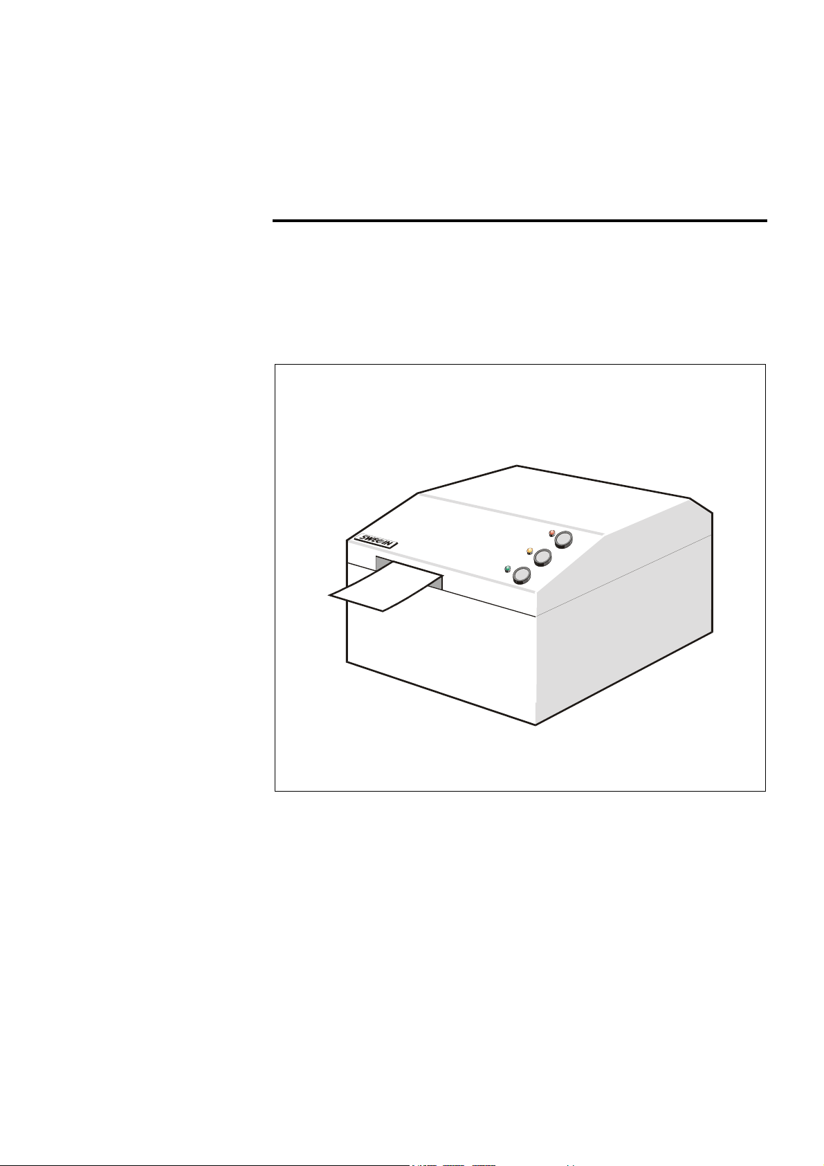
2PRODUCT PRESENTATION .........................................................................6
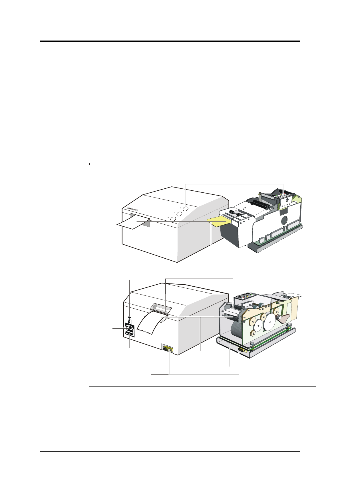
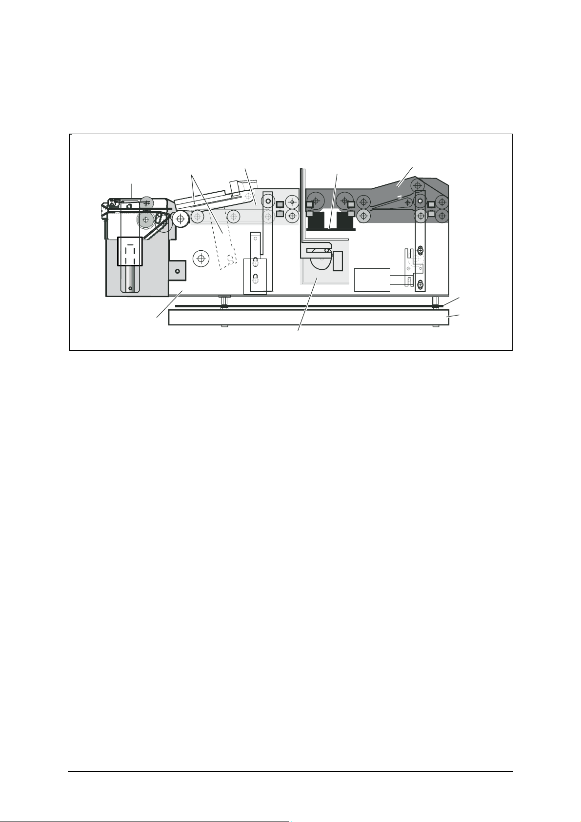
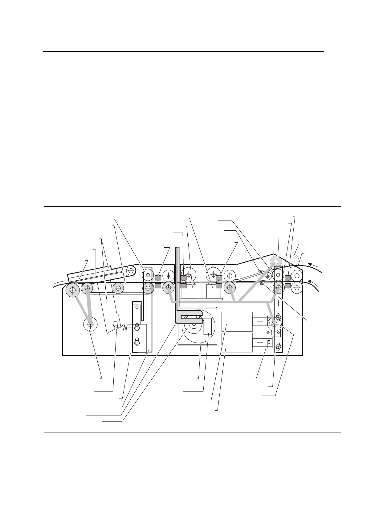
3FUNCTIONAL DESCRIPTION .......................................................................8
3.1 Standard TTPM2 model ..................................................................................8
3.2 Front Load 1, 2, and 3 .................................................................................. 10
3.3 TTPM2 with card dispenser.......................................................................... 16
3.4 Control board................................................................................................ 18
4MAINTENANCE ........................................................................................... 22
4.1 Preventive maintenance............................................................................... 22
4.2 Fault finding .................................................................................................. 24
4.3 Service checklist TTPM2 .............................................................................. 26
4.4 Parts removal and replacement ................................................................... 27
5ADJUSTMENTS........................................................................................... 33
5.1 Preparation ................................................................................................... 33
5.2 Ticket path adjustment ................................................................................. 34
5.3 Magnetic head pressure rollers adjustment ................................................. 37
5.4 Solenoids...................................................................................................... 38
5.5 Printers with front load.................................................................................. 40
5.6 Card dispenser ............................................................................................. 41
6REPLACEMENT PARTS............................................................................. 43
6.2 OEM version, final assembly........................................................................ 48
6.3 Card dispenser (CD200) version, final assembly......................................... 50
6.4 Basic module ................................................................................................ 52
6.5 Basic module, from autumn 2003................................................................. 60
6.6 Input module with one fanfold, and one single-ticket entry .......................... 64
6.7 Input module with two entries for fanfold ticket stock................................... 68
6.8 Presenter module, standard ......................................................................... 72
6.9 Presenter module, front load ........................................................................ 74
6.10 Printhead module assembly ......................................................................... 76
6.11 Cutter module ............................................................................................... 78
6.12 Front load 1 and 2 module ........................................................................... 80
6.13 Front load 3 module...................................................................................... 82
6.14 Card dispenser ............................................................................................. 84
September, 03 TTPM2 - Service Manual 3

7DRAWINGS.................................................................................................. 88
7.1 Control board interconnections .................................................................... 89
7.2 Control board, logic diagram SWC-2210 sheet 1......................................... 90
7.3 Control board, logic diagram SWC-2210 sheet 2......................................... 92
7.4 Control board, logic diagram SWC-2210 sheet 3......................................... 94
7.5 Control board, logic diagram SWC-2210 sheet 4......................................... 96
7.6 Magnetic board, logic diagram SWC-2229F ................................................ 98
REGISTER NOW!
If you wish to stay informed of product changes, manual updates etc., you are welcome to
subscribe to our bulletin service.
To register as a subscriber, either visit our web site www.swecoin.se to fill in your subscription
Enter the text Subscribe bulletins as the subject.
Do not enter any text in the message area.
AMENDMENTS TO REVISION C
Service checklist added
Required tools list added
Adjustments chapter added
Replacement parts chapter expanded
Card Dispenser added
AMENDMENTS TO REVISION D
Magnetic board drawings added
Various spare parts numbers updated
AMENDMENTS TO REVISION E
“Control Board Interconnections” diagram updated
Various spare parts numbers updated
AMENDMENTS TO REVISION F
Solenoid adjustments and sensor fauld finfing added, replacement parts updated
4 TTPM2 - Service Manual September, 03

1 INTRODUCTION
1.1 About this manual
This manual describes the design and function of the TTPM2 Ticket
Printer/Encoder, which creates credit-card-wide documents with magnetic
encoding and thermal printing.
The manual also contains maintenance instructions and replacement parts lists.
1.2 Updating
This manual will be updated as, from time to time, printer functions and features
may be added or amended. You will always find the latest edition on our web site
(www.swecoin.se). Printed copies of the current manual edition can be ordered
through e-mail, fax or phone.
If you require functions not found in the manual edition at your disposal, you are
welcome to consult one of our offices for information.
September, 03 TTPM2 - Service Manual 5

2 PRODUCT PRESENTATION
The TTPM2 uses the direct thermal printing technique and can print text, graphics,
EAN-13, 2-of-5 interleaved, and Code 39 bar codes.
Two magnetic tracks can be encoded with low coercivity or, in units so equipped,
with high coercivity.
Track combinations
• ISO track 2 at 75 BPI (bits per inch), and ISO track 3 at 210 BPI
• ISO track 1 at 210 BPI, and ISO track 2 at 75 BPI
• Center track at 75 BPI
The order-number on the type plate of the printer reveals what configuration a
printer has. The ordering information table in the Technical Specifications (separate
manual) lists all available versions.
Pushbuttons and indicators
Document exit
Optional front load mechanism
Upper document entry
Lower
document entry
Power ON/OFF
switch
Fuse
holder
Power
cable
receptacle
Power connector
RS 232 interface
connector
SW95065B-R1
Figure 1. Exterior of desktop and OEM versions of TTPM2
6 TTPM2 - Service Manual September, 03

The figure below shows the main parts of the OEM-type printer/encoder unit with
attached front load mechanism. Items in the figure, but not pointed to belong to the
basic module.
Output module Input module
Magnetic stripe
module
Cutter module
Control
board assy
Basic
module
SW95039A
Front load
module
(optional)
Protective
plate
Printhead
module
Figure 2. TTPM2 modules
September, 03 TTPM2 - Service Manual 7

3 FUNCTIONAL DESCRIPTION
The TTPM2 connects to a host computer, for example a workstation or a PC,
through the RS232 serial interface.
The host controls the operation of the TTPM2 by means of software commands.
A microprocessor on the control board interprets the commands and generates the
necessary control and data signals.
Besides the on-line mode, you can force the TTPM2 into a self-test mode pro-
ducing a printed and encoded ticket containing information about firmware
(EPROM) version.
3.1 Standard TTPM2 model
The figure below shows important parts of the standard printer/encoder unit. The
shaded lines indicate which stepper motor that drives the platen and the various
feed rollers.
(d) Thermal
print head
(c) Printhead
support plate
(a) Feed control roll
(n) Feed control roll
(h) Cutter pos.
sensor
(k) Upper input
sensor
(i) After cutter
sensor
(j) Feed control
roll
(z) Stepper motor
(ab) Engagement solenoid
(y) Engagement solenoid
(x) Engagement
solenoid (optional)
(ac) Feed control slide
(s) Feed control slide
(t) Stepper motor
(r) Rocker
(m) Lower input sensor
(f) Write head
(g) Read head
(ad) Knife
(ae) Carrier wheel
(v) Cutter-home
sensor
FRONT
BACK
(b) Feed belts (O-rings)
(p) Retaining
roll (option)
(q) Retaining
plate (option)
(o) Support
or feed roll
(l) Top-of-
form sensor
(aa) Printhead engage-
ment arm
(e) Print
platen
(u) Cutter motor
SW95040-R2
(af) Standby
position
sensor
(option)
Figure 3. Standard printer/encoder unit mechanics
8 TTPM2 - Service Manual September, 03

3.1.1 Document paths
See Figure 3.
The TTPM2 can handle the following document path combinations:
• Two software-selectable paths for fanfold or roll stock.
• One path for a fanfold or roll stock and one single-document path with
override function.
• Lower document path used for automatic insertion of single cards from an
optional card dispenser fitted at the back of the TTPM2. Upper document
path is not used.
The figure shows the TTPM2 design with two software- selectable paths for fanfold
or roll stock. The shaded lines indicate feed rollers directly driven by stepper
motors via gear wheels. The unshaded rollers are guide or pressure rollers.
In a TTPM2 with a single-document path, no motor drives the roller (o) in the input
module. The roller serves as a guide roller only.
The optional roller (p) is only fitted in the configuration with two fanfold or roll stock
paths. The roller presses the document against an optional retaining plate (q).
When the document is retracted to a standby position, the roller prevents the
document from slipping out of the input module.
Each document path has an opto-sensor detecting the insertion and the presence
of a document. Other opto-sensors alert the system about the position and the
presence of the document on its way through the printer/encoder unit.
3.1.2 Document feed control
See Figure 3.
The input and output modules have one feed control roller each, (a) and (j). The
rollers can be moved vertically by means of engagement solenoids and feed
control slides that presses the document against the feed roller or feed belts.
The rear, lower solenoid (y) moves the slide through an intermediate rocker plate
(r).
The rear, upper solenoid (x) is only fitted if the TTPM2 has two fanfold or roll stock
paths.
September, 03 TTPM2 - Service Manual 9

3.1.3 Cutting module
See Figure 3.
The knife in the cutting module moves by means of a DC-motor (u) with a
combined carrier and cam wheel (ae). The motor runs in one direction only during
normal cutting operations. A micro-switch sensor (v) detects when the knife
reaches its home position. If the mechanism cannot reach its home position,
possibly due to a paper jam or similar, the motor will run in the opposite direction
until the mechanism reaches its home position.
WARNING!
DANGER OF INJURY. Depending on the position of the carrier wheel on the cutter
module, the cutting mechanism may start moving when the mains power supply is
switched ON. KEEP HANDS AWAY WHEN SWITCHING ON THE POWER.
3.2 Front Load 1, 2, and 3
3.2.1 Design
The "Front Load options consist of an input/output module and a printhead lifting
mechanism. Front Load 2 and 3 options also has a lift mechanism for raising the
in/out feeder assembly to enable a document to be directed out through an
opening at the bottom of the input/output module to a waste bin.
SW97095-R2
Chute
In/out feeder assy Print head assy
Link
Solenoid
Paper
presence
sensor
Spring wire Pressure roll
Feed roll
Intermediate
gear
Screw
Stepper
motor
Platen
Plunger
Front
load 2
only
Lock shaft
(front load 1 only)
Figure 4. Front load 1 and 2 input/output module design
10 TTPM2 - Service Manual September, 03

The difference between Front load 2 and Front Load 3 is that FL2 holds the ticket
when it is ready so that the customer can take it from the printer while FL3 fylly
ejects the ticket so that it can fall down into a tray or bowl and the customer can
take it from there.
Chute
FL3 feeder assy Print head assy
Link
Solenoid
Paper
presence
sensor
Pressure roll
Feed roll
Intermediate
gear
Screw
Stepper
motor
Platen
Plunger
SW97095FL3
Figure 5. Front load 3 input/output module design. Note that the feed roller is in the very
front of the unit so that the ticket can be dropped into a bowl.
September, 03 TTPM2 - Service Manual 11

Printhead module assy
Micro switches
Actuator arm Adjustment plate Lock screw
Eccentric
cam wheel
SW97093B
Print platen Front load
module
Figure 6. Printhead lifting mechanism design (optional)
3.2.2 Function
FEEDING THE DOCUMENT IN
When the paper presence sensor detects a document, the printhead lifting
mechanism lifts the printhead and the stepper motor starts turning.
Printhead module assy
SW97093A
Print platen
Figure 7. Printhead lifted to accept document inserted at the front
12 TTPM2 - Service Manual September, 03

The document is fed through the front load input/output module into the ordinary
”output module” now also serving as an input device. A leaf spring ensures that the
document is kept pressed against the running feed belts to get sufficient friction.
SW97096-R2
Document
Leaf spring
Paper presence
detector
Feed roll
Stepper motor
Print head
Figure 8. Document is fed through into the ordinary output module
The document moves all the way into the upper rear document path. The
application program decides whether the document should be decoded, encoded,
printed, or disposed of.
September, 03 TTPM2 - Service Manual 13

FEEDING THE DOCUMENT OUT
Returning the document through the input/output module (can also be fed out
through the rear document path) is the reverse of feeding the document in. Note
that the document is guided out through the horizontal path (see arrow).
SW97098
Document
Figure 9. Feeding the document out the normal way
14 TTPM2 - Service Manual September, 03

Alternatively, the document can be fed out downward into a waste bin or similar
(with Front Load 2 or 3 option). This is affected by a software command that
actuates the solenoid that pushes the link upward and pivots the input module so
that the document is guided downward and out.
SW97099-R1
Document
Deflection
plate
Solenoid
Link
In/out feeder
Figure 10. Dropping the document into a waste bin or similar
September, 03 TTPM2 - Service Manual 15

3.3 TTPM2 with card dispenser
3.3.1 Design
In the TTPM2 version with card dispenser, both the TTPM2 (desktop or OEM
mechanism) and the card dispenser are mounted on a common base plate
(position 9Figure 11).
The dispenser is connected to the control board inside the TTPM2. The serial
interface connector on the control board "is moved" to the back of the card
dispenser by means of an extension cable 2.
SW98077
1
2
3
4
5
6
7
8
9
1011
12
13
14
Figure 11. TTPM2 printer fitted with optional card dispenser. The naked TTPM2 OEM mechanism can
also be equipped with a card dispenser.
The card dispenser is factory adjusted to a specific card thickness, usually
0.18 mm to 0.25 mm as indicated on a label on the dispenser. Using thicker or
thinner tickets will cause paper jam.
The ticket stock should be oriented with the magnetic stripe down to the left (or
center) as seen from the front of the TTPM2.
16 TTPM2 - Service Manual September, 03

3.3.2 Function
SW97126C
Counter
turning roll
Ticket output
sensor
Guide roll
Clutch
solenoid
Clutch
engagement
arm
Kicker
roll
Front belt
adjustment arm
Rear belt
adjustment arm
Motor
Ticket magazine
Ticket guide
Out-of-tickets
sensor
Pressure roll
Feed
rolls
Figure 12. Card dispenser function
The kicker roller forces the bottom tickets forward towards the feed rollers who feed
the tickets through a narrow opening that is adjusted for the ticket thickness used.
The counter-turning roller returns any extra tickets back to the pile in the ticket
magazine, while the feed rollers feed the selected ticket forward to the lower ticket
entry of the printer.
The out-of-ticket, and ticket output sensors are not used as the TTPM2 itself has
sensors inside its lower ticket entry.
September, 03 TTPM2 - Service Manual 17

3.4 Control board
See Figure 13. TTPM2 functional block diagram on page 21, and the logic diagram
in Chapter 5.
3.4.1 Microprocessor system
The main parts of the microprocessor system are
• 80C320 processor
• 64 K EPROM (27C512-12)
• 128 K battery backed-up static RAM (SRAM 628128)
• Two programmable I/O ports (8255)
3.4.2 Static RAM
The SRAM stores system parameters, downloadable fonts and print data. The lat-
ter is saved in a page memory area that can be further split into one area for fixed,
recurring, information and one area for variable information.
When the +5 V falls below a specific level, a voltage control circuit (U15) maintains
the SRAM contents with a back-up voltage supplied by a lithium battery cell.
CAUTION!
DANGER OF EXPLOSION if the lithium battery on the main board is incorrectly
replaced. DO NOT SHORT-CIRCUIT THE BATTERY. Replace only with the same
or equivalent type recommended by the manufacturer. Dispose of used batteries
according to the manufacturer's instructions.
The position of DIPswitch No. 4 decides if the page memory should be erased
automatically after each printed document.
Switch 4 ON = Clear all fixed and variable data after printing (auto clear)
OFF = Do not clear.
3.4.3 Printing
The printhead has 384 heating elements in a single line. This corresponds to 48
bytes of print data per dot line. The lateral resolution is 7.52 dots per millimeter.
The longitudinal resolution is 6 dots per millimeter.
The printhead has its own CPU-like logic circuitry with a separate 4 MHz oscillator.
Data to be printed is transferred on the data bus to the printhead, where the data is
shifted byte-wise into a 48-byte wide register before a dot line is printed.
The thermal coating on the document changes from white to black color at a spe-
cific temperature. The warmer the printhead, the less heating energy is needed and
vice versa. Therefore, the printhead contains a thermistor connected to a voltage
controlled oscillator (U11) on the control board. The frequency of the output signal
TEMP is proportional to the printhead temperature. The microprocessor uses the
TEMP signal to set the duty cycle of the regulated voltage applied to the heating
elements.
18 TTPM2 - Service Manual September, 03

3.4.4 Magnetic stripe encoding and reading
There are alternative magnetic stripe modules for encoding and reading of two ISO
tracks (track 1 & 2 or 2 & 3) with low or high coercivity. A center track is also
available, but the circuitry for track 2 is then used. The module is connected to the
control board through connector J3.
Data write and enable signals are transferred to the magnetic stripe module
through the I/O port (U5).
Read clock signals (MCRCLK1, MCRCLK2) and data signals (MCRDATA1,
MCRDATA2) are transferred directly to the microprocessor (U2), the clock signals
as interrupts.
The setting of DIPswitch No. 3 affects the magnetic stripe function as follows:
Switch 3 ON = Disable read-after-write of ISO magnetic track 3 data.
OFF = Enable read-after-write of ISO magnetic track 3 data.
3.4.5 Cutting
The DC-motor first turns in one direction to perform the cutting. The cam wheel
actuates the micro-switch sensor when the mechanism reaches its home position
again. At this moment, the motor is forced to a quick stop as the drive circuit for
turning the motor in the opposite direction is activated momentarily.
3.4.6 Communications interface
The TTPM2 communicates with the host through the RS232 serial interface. The
transfer rate is selectable between 9600 or 19200, and 115200 baud. Circuit U13
adapts the TTL-levels to RS232 levels.
The communication protocol is
• 8 data bits
• 1 stop bit
• No parity
• XON/XOFF or RTS/CTS handshaking (see below)
The setting of DIPswitches 5 and 6 affects the communication as follows:
Switch 5 ON = XON/XOFF
OFF = RTS/CTS
Switch 6 ON = ACK/NAK (+ error code) enabled
OFF = Disabled (silent)
September, 03 TTPM2 - Service Manual 19

3.4.7 Power supply
The power supply unit (PSU) is of the switched mode type and supplies +5V and
+24V to the control board.
A relay (U21) on the control board switches ON the +24 V after the +5 V is estab-
lished. This is to prevent the drive circuits in the printhead from becoming damaged
since their status is undefined before the +5 V is at correct level. The reason why
the design uses a relay instead of a transistor switch, is that the current through the
printhead can rise to approximately 8 A.
NOTE! — At these high currents it is essential that the leads and connectors be in
good condition. Excessive resistance in these parts may cause very strange
behavior of the printer.
The table lists the pin configuration in power connector J5:
Pin Voltage
1 +5 V
2 Ground
3 +24 V
4 +24 V
5 Ground
6 Ground
20 TTPM2 - Service Manual September, 03
Other manuals for TTPM2
3
Table of contents
Other Swecoin Printer manuals

Swecoin
Swecoin TTP 101 User manual

Swecoin
Swecoin TTP 101 User manual

Swecoin
Swecoin TTPM3 User manual

Swecoin
Swecoin TTPM2 Assembly instructions

Swecoin
Swecoin TTP 101 User manual

Swecoin
Swecoin TTP 2000 User manual

Swecoin
Swecoin TTP 5000 User manual

Swecoin
Swecoin TTP 2000 User manual

Swecoin
Swecoin TTP 5000 User manual

Swecoin
Swecoin TTP 5250 User manual