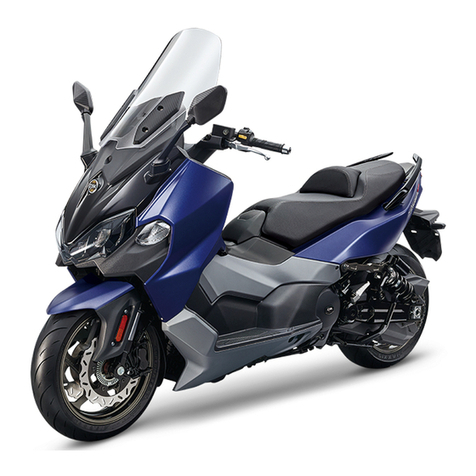
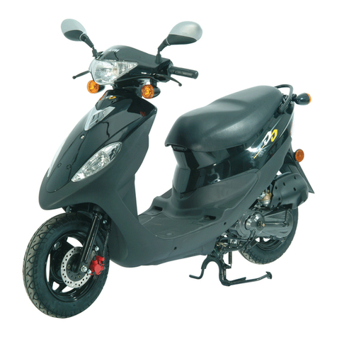
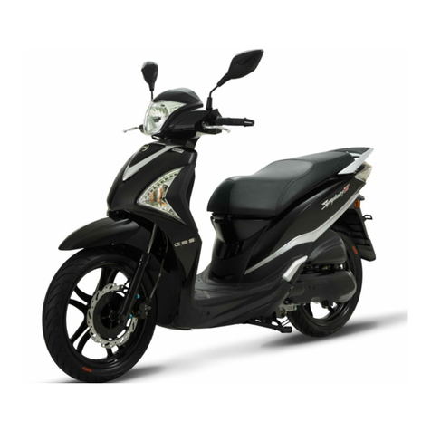
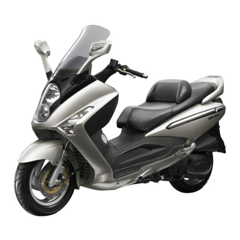
Sym JET 50 series User manual

OWNER’S MANUAL

THE ARTICLES MENTIONED BELOW ARE APPLICABLE ONLY
FOR THE UNITED STATES AND CANADA.
1. NOISE EMISSION WARRANTY
SANYANG INDUSTRY CO.,LTD. warrants that this exhaust system, at the time of sale,
meets all applicable U.S. EPA Federal noise standards. This warranty extends to the first
person who buys this exhaust system for purposes other than resale, and to all subsequent
buyers. Warranty claims should be directed to:
3,chung-Hua Road, Hukou, Hsin-Chu Taiwan, R.O.C
Tel:+886 35981911 Fax:+886 35981844
2. TAMPERING WARNING
Tampering with noise control system prohibited. Federal law prohibits the following acts or
causing thereof:
(1) The removal or rendering inoperative by any person other than for purposes of
maintenance, repair, or replacement, of any device or element of design incorporated
into any new vehicle for the purpose of noise control prior to its sale or delivery to the
ultimate purchaser or while it is in use, or
(2) The use of the vehicle after such device or element of design has been removed or
rendered inoperative by any person.
Among those acts presumed to constitute tampering are the acts listed below.
(1) Removal of, or puncturing the muffler, baffles, header pipes or any other component
which conducts exhaust gases.
(2) Removal or puncturing of any part of the intake system.
(3) Lack of proper maintenance.
Replacing any moving part of the vehicle, or parts of the exhaust or intake system, with parts
other than those specified by the manufacturer .t80
3. SAFETY INFORMATION
!Always wear your helmet (dot approved) correctly fastened. Do not carry loose items and
always wear suitable protective clothes, and protective eyewear.
!Good psychophysical conditions are very important for safe operation.
!Do not operate under the influence of drugs and/or alcohol.
!Do not operate in state of physical fatigue or drowsiness.
!Slow down on slippery surfaces , unfamiliar terrain and when visibility is reduced.
!Be alert when operating this vehicle.
!Do not exceed weight capacity.
!The safety, stability and handling of this motorcycle may be adversely affected by the
addition of accessories or luggage.
!Do not install accessory or replacement parts not approved by sym.
!Failure to follow these warnings could lead to an accident, serious injuries or death.
!Use unleaded fuel octane rating (R+M)/2 method of between 87&92.
!Read owners manual carefully before operating this scooter.
!Obey posted speed limit and other traffic signs and signals.

4. SAFETY DEFECT REPORT
SANYANG INDUSTRY CO., Ltd.
NO. 3,chung-Hua Road
Hukou Shiang
Hsin-Chu County, 303
Taiwan, R.O.C
Reporting Safety Defects
If you believe that your vehicle has a defect which could cause a crash or could cause injury
or death, you should immediately inform the National Highway Traffic Safety Administration
(NHTSA) in addition to notifying Sanyang Industry Co., Ltd.
If NHTSA receives similar complaints, it may open an investigation, and if it finds that a safety
defect exists in a group of vehicles, it may order a recall and remedy campaign.
However, NHTSA cannot become involved in and individual problems between you, your
dealer, or Sanyang Industry Co., Ltd.
To contact NHTSA you may call the Vehicle Safety Hotline toll-free at 1-888-327-4236
(TTY:1-800-424-9153);go to http://www.safercar.gov; or write to :
Administrator, NHTSA
400 Seventh Street SW.,
Washington, DC 20590
You can also obtain other information about motor vehicle safety from http://www.safercar.gov.

Content/ Subject
1
1. Contents
1. Contents ........................................................................................................................ 1
2. Control location .............................................................................................................. 3
3. Before riding .................................................................................................................. 8
4. Safety riding ................................................................................................................... 8
5. Driving ............................................................................................................................. 9
6. Use genuine spare parts ............................................................................................... 9
7. Use of each component ............................................................................................... 10
Gauges ........................................................................................................................ 10
Operation of ignition switch ......................................................................................... 13
Use of buttons ............................................................................................................. 14
Saddle lock .................................................................................................................. 15
Safety helmet hook ........................................................................................................ 15
Storage box ..................................................................................................................... 16
Fuel tank cap ............................................................................................................... 16
Brake ........................................................................................................................... 16
Parking method ........................................................................................................... 17
8. Important points and cautions for starting engine ........................................................ 18
9. The best way to drive off ............................................................................................. 19
The control of throttle valve handle ............................................................................. 19
10. Inspection and maintenance before riding ................................................................... 19
Routine inspection ....................................................................................................... 19
Inspection and replenishment of engine oil ................................................................. 20
Inspection of fuel level ................................................................................................. 20
Transmission oil inspection and change ...................................................................... 21
Inspection and adjustment of brake free play .............................................................. 21
Disc brake inspection [Depending on models] ............................................................ 22
Throttle valve handle clearance adjustment.................................................................. 23
Inspection and maintenance of battery ........................................................................ 23
Tire inspection ............................................................................................................. 24
Steering handle front shock absorbers inspection ....................................................... 25
Checking and changing fuses ..................................................................................... 25
Checking the turn signal lights and horn ..................................................................... 26
Checking the front and rear lights ................................................................................ 26

1. Contents
2
Checking the brake light .............................................................................................. 26
Checking for fuel leakage ............................................................................................ 26
Checking the lubrication of body’s various mechanisms ............................................. 26
Checking the spark plug .............................................................................................. 27
Checking the air cleaner .............................................................................................. 27
11. When there is an abnormal condition or a trouble ....................................................... 28
Diagnosis when engine does not start ......................................................................... 28
12. Periodical Maintenance Schedule ............................................................................... 29
13. Specification ................................................................................................................ 30
14. Postscript ..................................................................................................................... 32

3
2. Control location
MODE:JET 50/100 SERIES (BL05WA-6)
Head light
Front brake lever
Rear brake lever
Tail light
Helmet hook
Fuel tank cap
Engine number
Storage box
Muffler
Fuses / C.D.I. /
Eng. Oil tank cap
Light / Starter switch
High & Low beam /
Turn signal / Horn switch
Air cleaner
Frame number
Front turn signal
Ignition switch
Rear turn signal
Seat lock
Rear turn signal

4
2. Control location
MODE:BL05W6-A SERIES
Fuel tank cap
Light / Starter switch
Rear turn signal
Head light
Tail light
Engine number
Storage box
Fuses / C.D.I. /
Eng. Oil tank cap
High & Low beam /
Turn signal / Horn switch
Helmet hook
Air cleaner
Front turn signal
Ignition switch
Muffler
Rear brake lever
Front brake lever
Seat lock
Frame number

5
2. Control location
MODE:MASK SERIES (BF05W)
Head light
Front brake lever
Rear brake lever
Tail light
Rear turn signal
Helmet hook
Fuel tank cap
Engine number
Storage box
Muffler
Fuses / C.D.I. /
Eng. Oil tank cap
Light / Starter switch
High & Low beam /
Turn signal / Horn switch
Air cleaner
Front turn signal
Ignition switch
Rear turn signal
Seat lock
Frame number

6
2. Control location
MODE:BS05W SERIES
Head light
Front brake lever
Rear brake lever
Tail light
Helmet hook
Fuel tank cap
Engine number
Storage box
Muffler
Fuses / C.D.I. /
Eng. Oil tank cap
Light / Starter switch
High & Low beam /
Turn signal / Horn switch
Air cleaner
Front turn signal
Ignition switch
Rear turn signal
Seat lock
Frame number

7
2. Control location
MODE:Jet SportX 50 SERIES (BK05W)
Head light
Front brake lever
Rear brake lever
Tail light
Fuel tank cap
Engine number
Storage box
Muffler
Fuses / C.D.I. /
Eng. Oil tank cap
High & Low beam /
Turn signal / Horn switch
Air cleaner
Ignition switch
Rear turn signal
Seat lock
Frame number
ENG. Stop / Starter switch

8
3. Before riding 4. Safe riding
This manual describes the correct usage of this scooter including safety riding, simple inspection methods
and so on.
For a more comfortable and safety riding, please read this manual carefully.
Thank you very much for your patronage
In order to maximize your scooter’s performance, a periodical inspection and maintenance should be
completely carried out. We recommend that after riding your new scooter for the first 300 kilometers,
you should take your scooter to the original dealer for an initial inspection, and to have your scooter
inspected periodically every 1,000 kilometers thereafter.
!In case the scooter’s specifications and construction are modified and different from the photos and
diagrams on the owner’s manual/catalogues, the specifications and construction of the actual scooter
shall prevail.
4. SAFE RIDING
It is very important to be relax and clothe properly when driving, observe traffic regulations, do not rush,
always drive carefully and relaxed.
Usually, most people would ride their newly bought scooter very carefully, but after they became familiar
with their scooters, they tended to become reckless which may result in an accident.
To remind you:
!Please wear a safety helmet, and properly tighten the chin belt when riding a scooter.
!Clothes with open or loose cuffs may be blown by wind and cause the cuffs to get caught on the
steering handle and thus affects riding safety. So, put on clothes with tight sleeves.
!Hold the steering handle by both hands when riding. Never ride with only one hand.
!Observe the speed limit.
!Perform periodical maintenance and inspection in accordance with the schedule.
WARNING!!
!To avoid getting burned by exhaust pipe when taking a passenger. Make sure your passenger has
put his/her feet on the pedals.
!After running, the exhaust pipe is very hot, be careful not to get burned when conducting an
inspection or maintenance.
!After running, the exhaust pipe is very hot, select a suitable location to park your scooter to avoid
others getting burned by the exhaust pipe.
CAUTION:
!Modified scooter will affect its structure or performance, and cause poor engine operation or exhaust
noise, which will result in shortening the scooter’s service life. Besides, modification is illegal and
does not conform to the original design and specifications. A modified scooter will not be covered
by warranty, therefore, do not modify your scooter at will.
!Tire and rim modifications will make it unsafe to ride and may cause severe injury or death.

9
5. Driving 6. Use genuine spare parts
!Keep the related parts of your body such as arms, palms, lumbar, and toes relax and ride with the
most comfortable posture in order to be able to react quickly whenever it is necessary.
!Rider’s posture will great influent riding safety. As for the riding position, please always keep your
body’s gravity on the center of seat. If your body’s gravity is placed on the rear of seat, the front
wheel load will be reduced, this can cause steering handles shaking. Riding in this way is
dangerous.
!It will be much easier to make a turn if rider inclines his body inward when turning. On the other
hand, the rider will feel unstable if his body and the scooter do not incline.
!On bumpy, unleveled and slope road, the road condition may change often, driving on these roads
may become very unstable. To drive safely and smoothly, know your road condition before hand,
slow down, and hold the handle firmly with aid of your shoulder.
!Suggestion: Do not load objects on the front pedals unnecessarily, to avoid affecting the riding safety
and the operation of steering handle.
CAUTION:
!Feeling on the handle is different when the vehicle is with load or without load. Over-load will make
steering handle swing and then influent riding safety. Thus, please be ware of load weight.
!Overloading the scooter will cause the scooter to become unstable and hard to maneuver, it may
cause serious damage to the tires and rims, as well as it may change the center of gravity, which
could result in an accident that could cause injury or death. Do not exceed the maximum authorized
load.
CAUTION:
!Please do not load cargo or luggage on places where are not designed for loading to prevent danger
and damage.
!Do not place rags or similar objects between the storage compartment and engine to avoid engine
seizure because of inadequate engine oil supply.
SUGGESTION
◎To maximize the scooter’s performance and prolong its service life:
The first month or first 1000km is the wear- in period for the engine and components. Avoid
rapid acceleration, and keep the speed below 60km/hr.
6. USE GENUINE SPARE PARTS
In order to maintain the scooter’s best performance, each part’s quality, material, and machined precision
must conform with the design requirements. “SYM Genuine Spare Parts” were made from the same
high quality materials used for the original scooter. No parts would be sold to the market until they could
meet the designed specifications through sophisticated engineering and stringent quality control.
Therefore, it is necessary to purchase “SYM Genuine Spare Parts” from “SYM Authorized Dealers or
Franchised Dealers” when replacing spare parts. If you buy cheap, or fake substitute parts from the
market, no guarantee can be provided either for the quality or durability. Also, it may result in
unexpected troubles and lower the scooter’s performance.
!Always use SYM Genuine Spare Parts to keep your scooters pure blood and to ensure its long
service life.

10
7. Use of each component
Gauges
Model : JET SERIES
Model : MASK SERIES
Fuel Gauge
Turn Signal Indicator
High Bean Indicator
Engine Oil Warning Light
Speedometer
Odometer
Fuel Gauge
Turn Signal Indicator
High Bean Indicator
Engine Oil Warning Light
Speedometer
Odometer
Turn Signal Indicator

11
7. Use of each component
Model : BS05W SERIES
Model : BL05W6-A / G100P2 SERIES
Model : BK05W-6 SERIES
Fuel Gauge
Turn Signal Indicator
High Bean Indicator
Engine Oil Warning Light
Speedometer
Odometer
Fuel Gauge
Turn Signal Indicator
High Bean Indicator
Engine Oil Warning Light
Speedometer
Odometer
Clock
Turn Signal Indicator
High Bean Indicator
Engine Oil Warning Light
Turn Signal Indicator
Speedometer
Odometer/ Clock
Fuel Gauge
Fuel Warning Indicator
Tachometer
“MODE” Button
“SET” Button
Brightness Button

12
7. Use of each component
CAUTION:
Do not wipe plastic components, e.g. instrument panel, headlight, with organic solvents such as
gasoline…etc to avoid damaging these components.
1. Fuel Gauge
The pointer in this gauge shows how much fuel remains in the tank.
The pointer stays in “E” position when key switch is turned to “OFF.”
When key switch is turned to “ON”, and the “pointer” also in “E” position (red area). Refuel
immediately.
2. Turn Signal Indicator
The left or right Indicator will be flashing according to the operated directions of turn signal light switch
when it is turned on.
3. High Beam Indicator (If installed)
This indicator comes on with high beam headlight is turned on.
4. Engine Oil Warning Light
Turn the main switch to the “ON” position, if the oil warning light comes on continuously, this indicates
the engine oil level is too low, add oil as required.
WARNING:
!To continue drive the vehicle under low oil level condition will result in an engine seizure due to lack
of lubrication of engine parts. It is therefore very important to bring your vehicle to your dealer for an
oil replenishment immediately whenever the warning light comes on continuously.
!Use only 2-cycle engine oil meeting Japanese Automobile Standard Organization FC specifications.
Otherwise, this company will not assume any responsibility for damages resulted from using
substandard engine oil.
※Recommended oil: SYM EXTRA 2X oil.
5. Speedometer
This shows your speed in kilometers per hour
(km/h) and in mileage per hour (mph).
6. Odometer
This odometer shows the total kilometers this
motor has been driven.
CAUTION:
Observe the speed limit to ensure drive safety.
7-1. Clock
Set time in 24 hour mode.
“M” – mode bottom: Press the “M’ bottom, the clock order shows “Time mode”, “Hour setting mode”,
“Minute setting mode”, ”Second setting mode”. Final back to the “time mode”.
“S” – set bottom: At “Hour setting mode” or “Minute setting mode” or ”Second setting mode”. Press
the “S” bottom once, numerical can be increase. If keeping on pressing for 2
seconds can accelerate the adjustment. Until to set free the bottom. (At “Second
setting mode”, the colon ”:” in the center will be flash for 1 seconds.
7-2. Clock
Please check the appendix for BK05W-6 series speedometer.P32

13
7. Use of each component
OPERATION OF IGNITION SWITCH
“ON” position
!Engine can be started in this position.
!Ignition switch key can not be removed.
“OFF” position
!Engine is shut off and can not be started in this
position.
!Ignition switch key can be removed.
“LOCK” position
!Turn the handle all the way to left, then press
down the key and turn the key to the “LOCK”
position on the left.
!In this position, the handle is locked and the
key can be removed.
!To unlock, simply turn the key from “LOCK” to
“OFF”.
CAUTION:
!Never operate the ignition switch key when the scooter is running. To turn the ignition switch to
“OFF” and “LOCK,” will shut off the electrical system and that may result in a dangerous accident.
Therefore, the ignition switch can only be turned off after the scooter has been completely stopped.
!Always remove the key and be sure to take the key away with you after locking the steering handle
before leaving your scooter.
!If ignition switch remains in the “ON” position for a prolonged period after the engine has been
stopped, the battery’s capacity will be reduced and this may affect the engine’s start ability.
IGNITION SWITCH

14
7. Use of each component
USE OF BUTTONS
"Light Switches (If installed)
OR
When the switch is turned to this position,
headlight, rear light, instrument panel light,
and position light will go on.
When the switch is turned to this position,
rear light, instrument panel light, and position
light will go on.
When the switch is turned to this position, all
lights will go off. (Depending on Models)
"Electrical Starter Button
This is the electrical starter button, it is used
for starting the engine.
When the ignition switch key turns to “ON”
and brake lever hold, and then press this
button down to start engine.
《This mechanism is designed for safety.
Thus, the front or rear brake lever must be
hold before using this button so that engine
can be started.》
CAUTION:
!Release this button immediately after engine
has been started, and never press the button
again to avoid damaging the engine.
!Do not use light system. Turn headlight and
turn signal lights to the “OFF” position when
the engine is being started.
Horn Switch
Head light switch
High / Low
Beam Switch
Turn Signal Switch
Electrical Starter Button
Warning signal
switch
Head light switch
Electrical Starter Button
High/Low Beam
Switch
Passing switch
Engine Stop
Switch

15
7. Use of each component
"High/Low Beam Switch (If installed)
This is the high and low beam of headlight switching switch. Press this switch to switch between high
and low beams.
This is for high beam.
This is for low beam. (Please turn to low beam when riding in city)
"Turn Signal Switch
Turn signal lights are used when turning left/right or changing lane.
Turn ignition switch to “ON”, and slide the turn signal switch to left or right. Then, the turn signal lights
will flash.
Right-side turn signal light flashing means you intend to make a right turn.
Left-side turn signal light flashing means you intend to make a left turn.
"Horn Switch
Press this button down when ignition switch is in the “ON” position, the horn will sound.
CAUTION:
!Do not press this button when you are in the no horn area.
SADDLE LOCK
"Unlock:
Insert your ignition switch key into the lock on the lower left of the saddle, and turn the key to the right.
Then, the saddle can be lifted up.
"Lock:
Press the saddle down and push it locks automatically.
CAUTION:
!Please do not put the key into the storage compartment after saddle is unlocked to prevent the key
from being locked inside and can not be removed when the saddle is locked.
!Be sure to remove the key after the saddle has been locked
SAFETY HELMET HOOK
!Open the saddle, and hook the safety helmet chin belt onto the hook, and then lock the saddle.
CAUTION:
!Please do not hang your safety helmet as usual on the hook when driving, to prevent it from
damaging the vehicle and affecting your driving safety.
•Engine Stop Switch
Switch to this position to turn off the engine when a state of emergency.
Switch to this position and the engine can be started.
•Passing Switch (If installed)
Turn ignition switch “ON” and press this button down. Then, the high beam of headlight will come on
immediately to warn the driver of the vehicle ahead that you intend to overtake him/her. (For overtaking, high
beam indicator will come on at this time) This button will return to original position after releasing

16
7. Use of each component
STORAGE BOX
#This box is located under the saddle.
#Maximum load capacity: 10kg.
#Do not store valuables in the box.
#Please make sure that seat cushion had been locked completely after it was down. Take out valuables
before washing to avoid wetting these objects.
#Do not place thermal sensitive objects in the box because of engine’s heat and high temperature.
FUEL TANK CAP
1. Insert ignition switch key into the lock on the fuel tank cap, and turn the key to the right, then the cap
can be removed.
2. Do not fill above the fuel upper limit when refueling.
3. Align the “△” mark
4. on the cap with the “△” mark on the body, and press down the cap in parallel until a “click” sound is
heard. That means the cap is locked (the ignition key now turns back to the left slightly). To remove
the ignition key, simply turn the key to the left and then remove it.
WARNING:
!Main stand should be put down on the ground, engine should be shut off and flames should be
strictly prohibited to ensure safety when refueling.
!Do not fill above fuel upper limit when refueling. Otherwise, fuel will flow out through a hole on the
cap that may damage the body’s painting, in serious cases, it may cause a fire to burn down the
scooter.
!Make sure the cap has been tighten properly.
BRAKE
#Use front and rear wheel brakes simultaneously when braking.
#Avoid unnecessary sudden braking.
#Using only the front brake or the rear brake increases the risk of falling because the scooter is tend to
pulled to one side.
#Avoid brake continuously for a long period of time because that may overheat the brakes and reduce
its braking efficiency.
#Slow down and brake early when riding in rainy days on slippery roads. Never apply the brakes
suddenly to prevent skidding and falling.
For Rear Wheel
For Front Wheel

17
7. Use of each component
PARKING METHOD
"When approaching the parking lot:
1. Turn on the turn signal light early, and pay attention to the vehicles in front, from rear, left and right, then
take the inner lane and approach slowly.
2. Return the throttle valve handle back to its original position, and apply brakes in advance. (Brake light
comes on when braking to warn drivers of vehicles behind.)
"When stop completely:
1. Press the turn signal switch back to its original position, and turn the ignition switch key to “OFF”
position to shut off the engine.
2. Get off the scooter from left side after the engine has been stopped, and select a parking place where
the scooter will not interfere with traffic and the ground is level, then put down scooter’s main parking
stand.
3. Hold the steering handle with your left hand, and hold down the front end of saddle or hold the parking
handle on the lower-left side of saddle with your right hand.
4. Press the main parking stand with your right foot, put down the main parking stand firmly on the ground.
To remind you: Lock the steering handle and remove the key after parking to prevent the scooter
from being stolen.
CAUTION:
Park your scooter at a safe place where it will not interfere with traffic.
This manual suits for next models
1
Table of contents
Other Sym Scooter manuals

Sym
Sym MAXSYM 400 User manual

Sym
Sym MIO ELECTRIC User manual

Sym
Sym JOYRIDE 300 2022 User manual

Sym
Sym XA05W4-EU Series User manual

Sym
Sym EuroMX 125 User manual

Sym
Sym ORBIT III XE05W2-EU Series User manual

Sym
Sym Citycom.300i User manual

Sym
Sym Jet 100 User manual

Sym
Sym 2009 FIDDLE II 125 User manual

Sym
Sym ATTILA RS-21 EFi 150 User manual

Sym
Sym JET 4 R 50 Series User manual

Sym
Sym Symply50 User manual

Sym
Sym JOYRIDE 125 User manual

Sym
Sym AK12W Series User manual

Sym
Sym Mio FS11W1-EU Series User manual

Sym
Sym Jet 4 125 User manual

Sym
Sym Citycom 300i User manual

Sym
Sym Fiddle II 50 SYM Series User manual

Sym
Sym MAXSYM 400i User manual

Sym
Sym Jet Euro X 50 User manual