Stratasys Bull Rider User manual

Solution Guide
Bull Rider - 3D Printed Scooter
print and assembly instructions
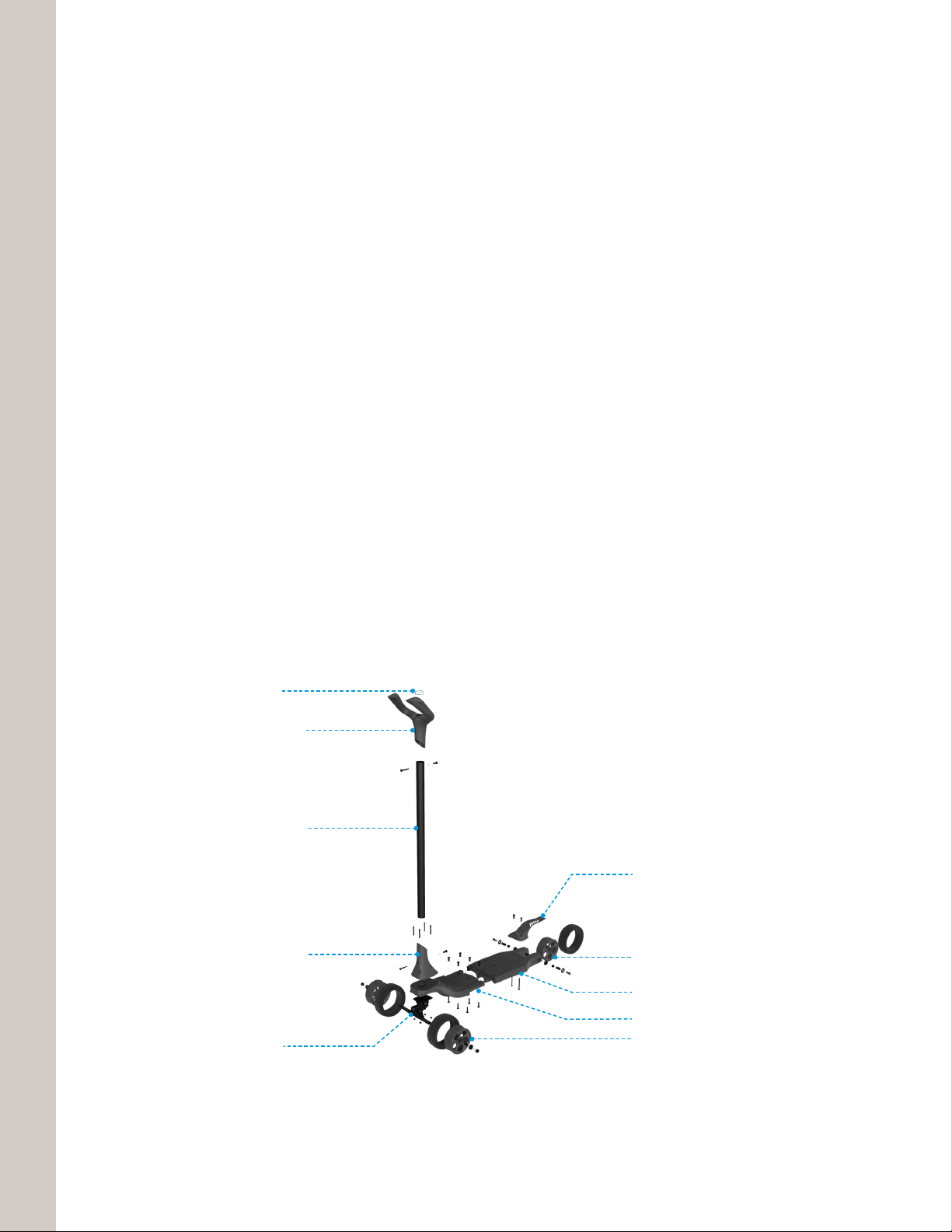
Scooter overview
The Bull Rider was designed by Slicelab in collaboration with Stratasys. The kick scooter is comprised
mostly of 3D printed parts designed specifically for the Origin One machine. The additional parts needed
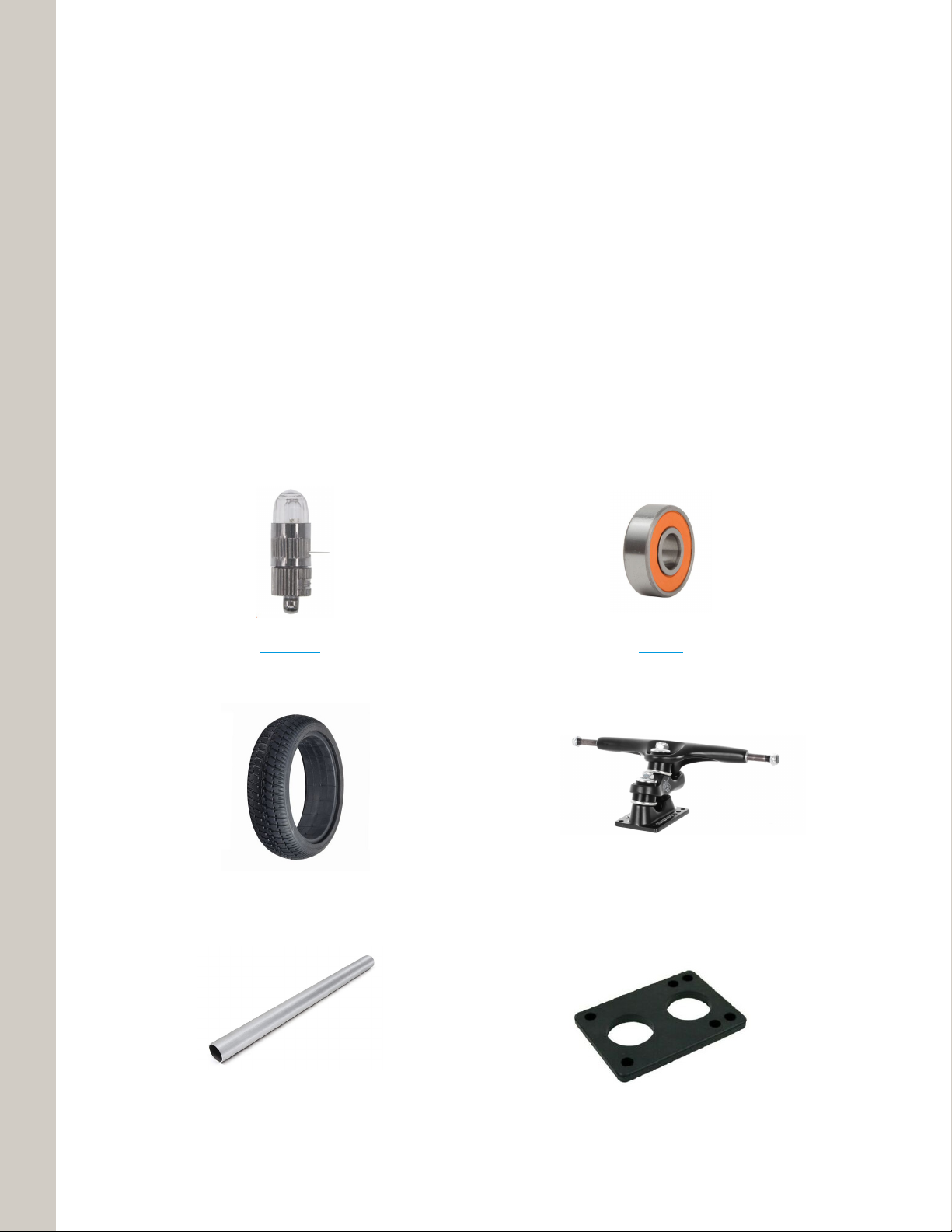
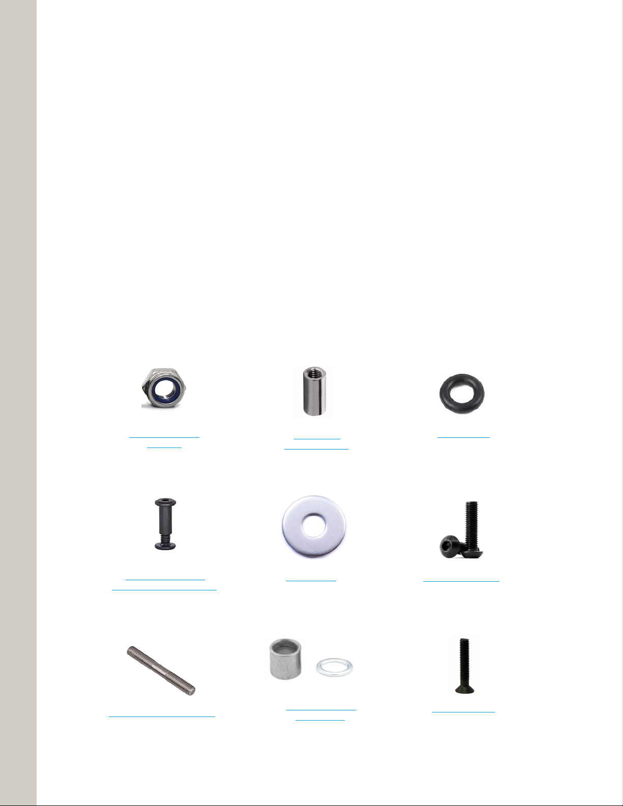
are off the shelf components that can be easily purchased online and customized to user needs. Examples
of such adjustments can be for the users height or weight metrics that impact how one rides the scooter.
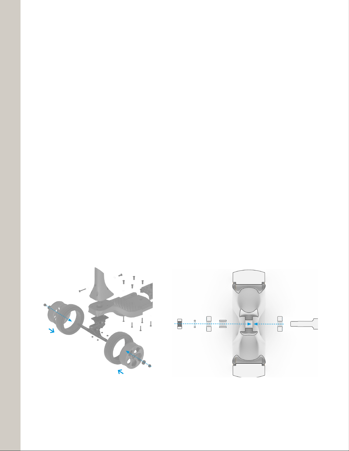
Additionally, there are components like the long-board trucks, that can be tightened or loosened to allow for
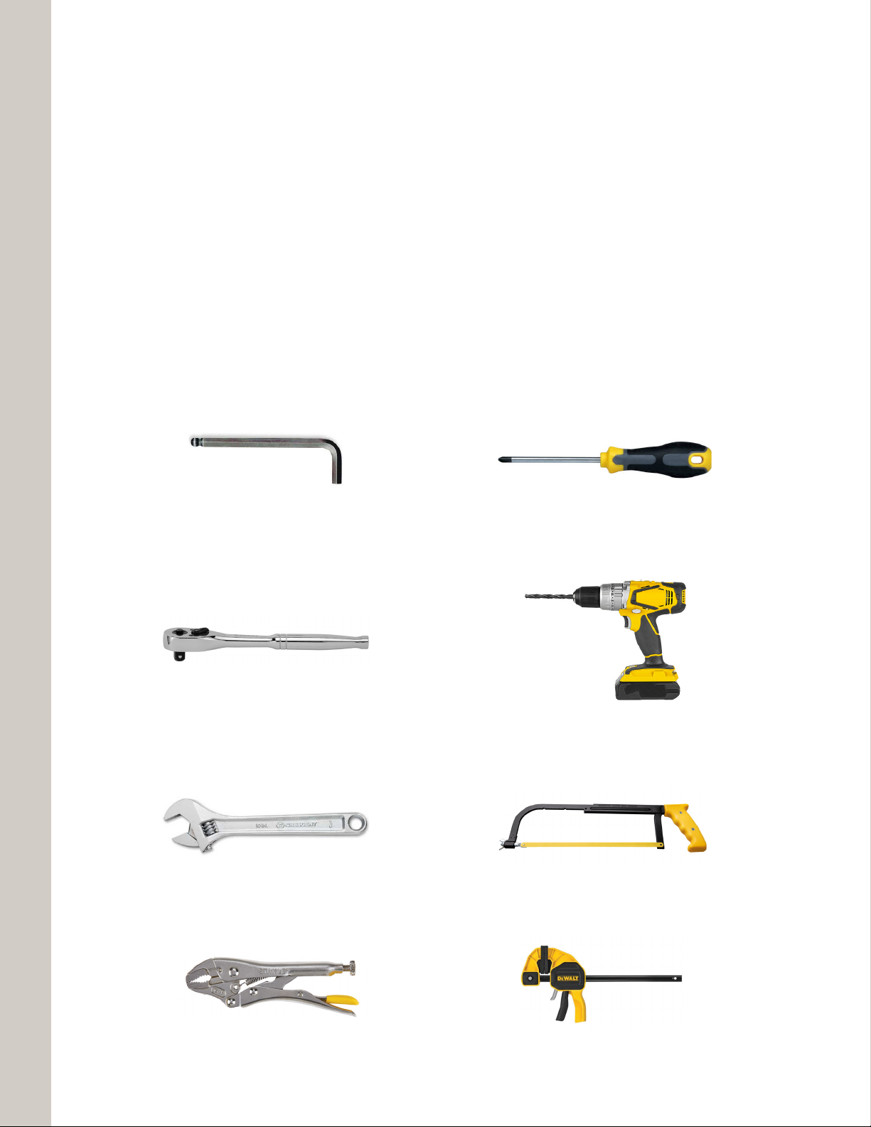
more or less responsiveness in steering. In the following pages, the required tool set and steps to complete
this assembly will be highlighted along with a list of the needed purchased parts and printed parts.

Solution Guide
Step by Step Assembly
Tools Needed (3)
Items to Purchase (4)
Hardware Needed (5)
Parts Overview (6)
Step 1: Stem base connection (7)
Step 2: Deck connection (8)
Step 3: Wheels to Truck (9)
Step 4: Rear axle connection (10)
Step 5: Rear wheel (11)
Step 6: Rear brake (12)
Step 7: Handlebar assembly (13)
Step 8: Light assembly (14)
Common Questions (15)
3D Print Instructions
Front Deck (17)
Back Deck (18)
Handlebar (19)
Stem Base (20)
Brake (21)
Wheels (22)
Light (23)
Support (24)
Bull Rider Assembly
table of contents

3
Solution Guide
Below are all the basic tools needed to assemble the scooter. Additional tools can be used to aid assembly.
Notes
The hardware that requires the Allen wrenches needs to be tightened from both sides, therefore, two tools
are needed at the same time in these steps.
Bull Rider
tools needed
Adjustable Wrench
Jaw Locking Pliers
Metal Hack Saw
Adjustable Clamp
Ratchet Set (3/8”, 1/2”) Power Drill w/ Metal Bits (1/4”,13/64”)
Allen Wrenches x 2 (A4, A8) Screw Drivers (Flat head, Phillips Head)

4
Solution Guide
Bull Rider
items to purchase
1.25” OD Aluminium pipe
6.5” Solid Rubber Tires Long-board Trucks
Battery LED Bearings
Long-board Riser 1/8”
Below is a list of the off-the-shelf parts that need to be purchased to assemble the scooter. Nearly all the
parts can be found online at Amazon and have the hyperlinks below the images for your convenience.
Notes
Some products can change online or be no longer available. Reference the sizes and specs carefully in the
case that a part needs to be substituted.

5
Solution Guide
Bull Rider
hardware needed
25mm Round
Connector Nuts M8
Double Sided Screw Rod M8x65
Socket Cap Screws M8
Socket Cap Barrel Nuts
(M6x20, M6x30, M6x45, M6x55)
1.75” Truck Screws
Rubber O Rings
Self-Locking Hex Nut
(1/2”, 3/8”)
Aluminium Washer &
Barring Spacer
Fender Washer
Below is a list of the off-the-shelf parts that need to be purchased to assemble the scooter. Nearly all the
parts can be found online at Amazon and have the hyperlinks below the images for your convenience.
Notes
Some products can change online or be no longer available. Reference the sizes and specs carefully in the
case that a part needs to be substituted.

6
Solution Guide
Referenced Parts
Reference the diagram bellow for the names of the parts in the overall assembly. There are 7 unique
parts that are 3D printed and 9 printed parts in total. The order of which the scooter is assembled will be
highlighted in the subsequent pages. Certain steps require unique methods of assembly because of the
tight spaces they lock into. All of the hardware is symmetrical along the length of the scooter but there are
certain hardwares that need to be inserted before others due to the nature of the geometry.
Notes
Socket Cap Barrel Nuts have a male and female ends. The female ends, which are thicker, should be
inserted first in all cases. Additionally, if prints have defects within the hardware slots, careful manual drilling
may need to be done to clear the hole.
Bull Rider
parts overview
Handlebar
Light
Stem Post
Stem Base
Truck
Front Deck
Back Deck
Brake
Back Wheel
Front Wheels

7
Solution Guide
Stem Base to Front Deck
Connect the Stem Base to the Front Deck with (4) 1.75” Truck Screws to the metal base plate of the trucks.
Make sure the 1/8” riser pad is sandwiched in-between the metal and rectangular slot on the underside of
the Front Deck. Use a 3/8” ratchet to get into the tight space and evenly tighten all around. Slide 4 rubber O
rings onto the top of the screws before putting them into the slots
Notes
Using a the Phillips head screwdriver, place the screws into the Stem Base, through the Front Deck, through
the Riser pad and through the metal truck below and flip the whole assembly while also pressing all the
parts together for an easier process to ratchet the hex nuts on.
Step 1
stem base connection

8
Solution Guide
Front Deck to Back Deck
Connect the Front Deck to the Back Deck with (2) M6x25 & (4) M6x45 Socket Cap Barrel Nuts. Make sure
to insert female side first, this may require some light hammer like tapping on the ends as the hardware fits
tightly within the slots. Use an M4 Allen wrench on either side to tighten evenly.
Notes
Slide 12 rubber O rings onto the top of the Socket Cap Barrel Nuts before putting them into the slots.
Step 2
deck connection

9
Solution Guide
Front Wheel Assembly
Mounting the wheels onto the axle, first by force fitting the rubber tires onto the 3DP wheels with the help of
a flat head screwdriver until they lock into place. Second, with hammer like tapping, insert the (2) bearings
into place on both sides of the wheel making sure to place the aluminum spacer in between the two. Lastly,
place the assembled wheel onto the axle adding the small washer on the outside before tightening the nut
with a 1/2” ratchet or adjustable wrench.
Notes
Do not over tighten the self-locking hex nut as it will restrict the wheel movement. Tighten large Kingpin nuts
(9/16”) as needed for ease of steering.
Step 3
wheels to truck
Hex Nut
Washer
Barring
Barring
Spacer
Rubber Tire
3DP Wheel
Truck Axel

10
Solution Guide
Rear Wheel Assembly
Create the same wheel assembly as the front wheels (Rubber tire, 3DP wheel, bearings, spacer). Set this
aside and screw a Hex Nut onto the Double Sided Screw Rod in such a way that the wheel assembly can sit
in the middle. Then screw the second hex onto the opposite side securing the wheel in place. Next, screw
the Round Connector Nuts onto both sides as seen in the zoom in below.
Notes
The Hex Nut can be challenging to place correctly at first along side the Round Connector Nuts. Use the
jaw locking pliers and/or a clamp to secure the Round Connector Nuts into place.
Step 4
rear axle
C
L
Socket Cap Screw
Fencer Washer
Back Deck
Round Connector Nut
Hex Nut
Rubber Tire
Double Sided
Screw Rod
Back Wheel
Axel Assembly
3DP Wheel

11
Solution Guide
Rear Wheel Calibration
Take this assembly and forcibly press it into the slot found at the bottom of the Back Deck. Next, add the
Button Head Socket Cap Screw with Fender Washer to each end, tightening them simultaneously while
keeping the wheel assembly centered on the deck. Using an M8 Allen wrench to tighten, make sure the
wheel can spin smoothly, too tight will bend/crack the 3DP.
Notes
Some sanding may need within the back slot of the part if it is too tight due to printing defects, shrinking
or warping. Keep the rear wheel spinning while calibrating to ensure the axle is lined up correctly with equal
gaps on either side of the tire.
Step 5
rear wheel
C
L
C
L
EQ
EQ

12
Solution Guide
Brake to Back Deck
Connect the Brake to the Back Deck half using (2) M6x55 Socket Cap Barrel Nuts. Make sure to insert fe-
male side first, this may require some light hammer like tapping on the ends as the hardware fits tightly within
the slots. Use an M4 Allen wrench on either side to tighten evenly.
Notes
Slide 4 rubber O rings onto the top of the Socket Cap Barrel Nuts before putting them into the slots.
Step 6
rear brake

13
Solution Guide
Referenced Parts
Cut the aluminum pipe down to the desired post length using a hack saw. Next, place the Handlebar and
Stem Base onto the aluminum post. Next, mark the centers of the holes and drill the hardware holes. Lastly,
connect the Stem Post to the Handlebar and the Stem Base using a M6x30 & M6x45 Socket Cap Barrel
Nuts. Make sure to insert female side first, this may require some light hammer like tapping on the ends as
the hardware fits tightly within the slots. Use an M4 Allen wrench on either side to tighten evenly.
Notes
When drilling into the shaft of the metal post, tightly secure the post onto a hard surface with proper
clamps. If possible, use a drill-press for more accurate results. Make sure to use two separate drill bits
for the different thicknesses of the socket cap barrel nuts. Reference the 3D printed part for which side is
which.
Step 7
handlebar assembly

14
Solution Guide
Light to Handlebars
Before putting the light into the slot at the top of the handle bars, pull the plastic tab that activates the battery
and twist the shaft clockwise to turn the light on. Next, fit the light and the clear Stratasys ‘S’ shaped piece
snug into the form fit openings.
Notes
Light needs to be shut on and off while not in use to preserve the battery. Removing the light can be
challenging pressed too deeply into the slot.
Step 8
light assembly

15
Solution Guide
FAQs
1. Do you really need the rubber O rings on all hardware
No, but they will provide additional cushioning on the 3D printed parts that could alleviate cracking issues
2. Does the height of the metal tube matter
Yes, the ergonomics of this scooter will work best when user grips the handlebars slightly below the waist
3. How tight should the trucks be for steering
Looser is better as it give a user more feedback and control as they steer and kick off, too tight may
prove hard to balance while trying to lean into a turn.
4. Should I tighten all hardware to the max
No, most of the hardware will do it job at a reasonable level of tightness, no need to crank down on the
metal parts especially considering they are impacting the 3DP pieces and could crack them.
Bull Rider
common questions

16
Solution Guide
Bull Rider
3D print instructions
Print tips
The majority of the parts except of the handlebar light are printed out of Dura56. In the following pages, de-
tailed print tips and instructions that highlight key elements needed to create successful prints for each part.
All the print files mentioned can be found on GrabCad

17
Solution Guide
Bull Rider
front deck
Print tips
Part volume: 1370 cc.
Material: Dura56
Be sure to add adequate resin to tray. It’s hollow and latticed inside which will capture some resin, so you’ll
need to add more than the normal +200mL to make sure you don’t run out. Suggest to start the print, then
top off the resin during the 1st layer delay. Be sure to drain resin from interior back into tray for re-use and
to avoid a mess. Print with conservative settings or use 8+ second delay time to account for large cross
sections and get the best surface quality.

18
Solution Guide
Bull Rider
back deck
Print tips
Part volume: 1469 cc.
Material: Dura56
Be sure to add adequate resin to tray. It’s hollow and latticed inside which will capture some resin, so you’ll
need to add more than the normal +200mL to make sure you don’t run out. Suggest to start the print, then
top off the resin during the 1st layer delay. Be sure to drain resin from interior back into tray for re-use and to
avoid a mess. Print with conservative settings or use 8+ second delay time to account for large cross sec-
tions and get the best surface quality.

19
Solution Guide
Bull Rider
handlebar
Print tips
Part volume: 340 cc
Material: Dura56
Be sure to add adequate resin to tray. It’s hollow and latticed inside which will capture some resin, so you’ll
need to add more than the normal +200mL to make sure you don’t run out.

20
Solution Guide
Bull Rider
stem base
Print tips
Part volume: 314 cc
Material: Dura56
Print with Dura56 conservative settings, or Increase delay time to 10+ seconds, to account for large cross
section and large unventilated volume, or re-support the part to alleviate the unvented volume.
Table of contents