0813-PrintedinGermany 9.6247.00 - 299.0.302
Der SYR Flanschdruckminderer 6247 wird zur Druckregelung
bei Anlagen mit Medien entsprechend unten stehender Spe-
zifikation verwendet. Der Einsatz eines Druckminderers redu-
ziert den Wasserverbrauch. Auch bei schwankenden
Versorgungsdrücken wird der Anlagendruck vom Druck-
minderer konstant gehalten.
Druckminderer für Flanschanschluß nach DIN EN 1567, mit
entlastetem Einsitzventil und koaxial angeordnetem Schmutz-
fänger; Maschenweite 0,6 mm. Druckmindererpatrone ohne
Ausbau der Armatur austauschbar. Gehäuse aus Rotguss;
Verbindungsmutter aus Messing; Gummiteile aus alterungs-
beständigen Elastomeren; Membrane gewebeverstärkt;
Schraubkappe aus glasfaserverstärktem Kunststoff.
Technische Daten:
Anschlussgröße: DN 65 - DN 100
max. Betriebsdruck: 16 bar
Ausgangsdruck: einstellbar von 1,5 bis 6 bar,
werkseitig voreingestellt auf 4 bar
max. Betriebstemp.: 30°C
Medium: Wasser, Druckluft, neutrale,
nichtklebende Flüssigkeiten, neu-
trale Gase
Einbaulage: beliebig
Durchflussleistung: DN 65: 24 m³/h bei Δp 1,1 bar
DN 85: 36 m³/h bei Δp 1,1 bar
DN 100: 56 m³/h bei Δp 1,1 bar
Anwendungsgebiet / Field of application
Ausführung / Design
Die Wartung des Druckminderers ist nach DIN 1988, Teil 8
geregelt. Die angegebenen Wartungsintervalle sind einzu-
halten. Der Druckminderer 6247 benötigt keine aufwendige
Wartung. Je nach Wasserqualität kann jedoch eine häufige-
re Reinigung der Druckmindererpatrone und des Schmutz-
siebes anfallen.
- Absperrventile schließen.
- Druckmindererpatrone entnehmen.
- Druckmindererpatrone und Schmutzsieb
mit kaltem, klaren Wasser reinigen.
- Druckmindererpatrone wieder montieren.
- Absperrventile öffnen.
- Nach Wartungen die Druckeinstellung überprüfen und ggfs.
korrigieren.
Vor dem Einbau ist die Rohrleitung durchzuspülen. Der Druck-
minderer ist unter Beachtung der Fließrichtung, angegeben
durch einen Pfeil auf dem Gehäuse, spannungsfrei in die
Rohrleitung einzubauen. Die Einbaulage ist beliebig. Nach DIN
1988, Teil 5 wird eine ausgangsseitige Nachlaufstrecke von
mindestens 5 x DN empfohlen.
Einbau / Installation
Wartung / Maintenance
Druckeinstellung /
Outlet pressure setting
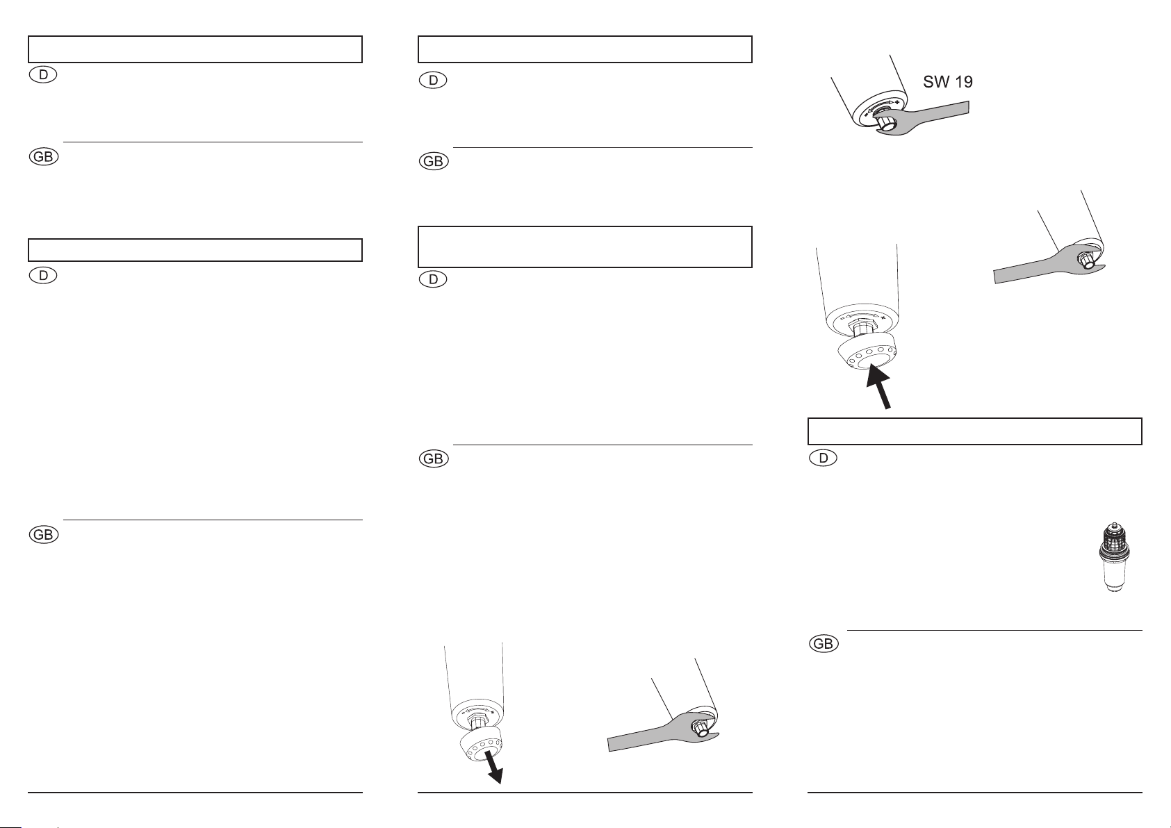
Ziehen Sie zur Einstellung des Ausgangsdruckes die Kappe
am Ende der Patrone ab (Abb. 1) und lösen Sie die Kontermut-
ter (SW 28) (Abb. 2).
Es wird empfohlen, den Druck im Ruhedruck einzustellen.
Drehen Sie die Stellschraube der Druckmindererpatrone z.B.
mit einem Maulschlüssel SW 19 nach minus (-), öffnen Sie eine
nachfolgende Zapfstelle, um den Druck zu entlasten und um
den Ausgangsdruck zu reduzieren (Abb. 3). Drehen Sie die
Einstellschraube der Druckmindererpatrone in Richtung plus
(+), bis der gewünschte Ausgangsdruck erreicht ist und
ziehen Sie die kontermutter wieder fest (Abb. 4). Stecken Sie
anschließend wieder die Kappe auf die Einstellschraube, um
eine ungewollte Verstellung des Ausgangsdruckes zu ver-
hindern (Abb. 5).
Abb./
Pict. 3
Abb./
Pict. 1
Abb./
Pict. 5
The pressure reducing valve with flange connection 6247
from SYR is designed to regulate the pressure in systems
operating with fluids in accordance with the specifications
mentioned below. The use of a pressure reducing valve
lowers the water consumption. The pressure reducing valve
also maintains a constant pressure within the system regardless
of fluctuating supply pressures.
Pressure reducing valve with flange connection according to
EN 1567, equipped with a spring-relieved single-seat valve
and a coaxially positioned strainer; mesh width 0.6 mm. No
need to disassemble the valve to exchange the pressure
reducer cartridge. Body made of gun-metal; union nut made of
brass; rubber parts made of ageing resistant elastomer;
reinforced membrane; screw cap made of glass fibre reinforced
synthetic material
Technical specifications:
Connection size: DN 65 - DN 100
Max. operating
pressure: 16 bar
Outlet pressure: adjustable in a range from 1.5 to 6
bar, factory set to 4 bar
Max. operating temp.: 30°C
Fluids: Water, compressed air, neutral,
non-adhesive fluids, neutral gases
Mounting position: any
Flow rate capacity: DN 65: 24 m³/h at Δp 1.1 bar
DN 85: 36 m³/h at Δp 1.1 bar
DN 100: 56 m³/h at Δp 1.1 bar
Flush the pipe prior to installation. Install the pressure reducing
valve in the pipe under consideration of the direction of flow
(arrow on the body). Do not apply stresses. Choose any
mounting position. It is recommended to plan a section of at least
5 x DN to allow turbulences to slow down.
Remove the cap at the end of the cartridge (pict. 1) to adjust
the outlet pressure and release the counternut of size 28
(pict. 2).
It is recommended to set the pressure at static pressure. Turn
the adjustment screw of the pressure reducer cartridge for
instance with a spanner of size 19 in the direction of the minus
symbol (-), open a downstream draw-off point to relieve the
pressure and to reduce the outlet pressure (pict. 3). Turn the
adjustment screw of the pressure reducer cartridge in the
direction of the plus symbol (+) until reaching the desired outlet
pressure and retight the counternut (pict. 4). Afterwards, put
the cap back on the adjustment screw to prevent any inadvertent
maladjustment of the outlet pressure (pict. 5).
The pressure reducing valve 6247 requires no complex
maintenance. However, depending on the water quality, it is
recommended to clean the pressure reducer cartridge and
the strainer on a regular basis (at least once per year)
- close the stop valves.
- remove the pressure reducer cartridge.
- clean the pressure reducer cartridge and the strainer
with cold and clear water.
- reassemble the pressurer reducer cartridge.
- open the stop valves.
- after servicing, check the pressure setting and adjust it if
required .
Abb./
Pict. 2
Abb./
Pict. 4
SW 28
SW 28


