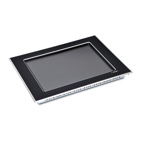
syslogic IPC/RSL8-X E Series Operator's manual

u s e r d o c u m e n t a t i o n
IPC/RSL8xxx-XxxxE
Document Ordercode: DOC/IPC_RSL8-E
Revision
Date
Author
Modification
1.0
05.06.2015
U. Müller
Release
1.1
23.05.2016
U. Müller
technical data corrected
1.2
17.10.2016
U. Müller
added USB current limit values
1.3
24.01.2017
U. Müller
extended safety information and D-coded LAN
1.4
23.02.2017
F. Liechti
Added safety information on power supply
1.5
22.03.2017
U. Müller
Reduced supply voltage to nominal 24V only
1.6
09.05.2017
U. Müller
Added safety information for power wiring
1.7
20.06.2017
S. Mutter
Added IPC/RSL8H19-BxxxE systems
1.8
04.07.2017
S. Mutter
Added EMC Standards for -BxxxE systems
1.9
15.12.2017
U. Müller
added backup time, corrected LVDS signals

IPC/RSL8xxx-XxxxE: user documentation
DOC/IPC_RSL8-E; V1.9
© Syslogic Datentechnik AG, Switzerland, http://www.syslogic.com 2/80
Contents
1Introduction 7
1.1. General remarks 7
1.2. Contents of this Documentation 7
1.3. Additional Products and Documents 7
1.1.1. Hardware Products 7
1.1.2. Software Products 7
1.1.3. Documents 8
1.4. Items delivered 8
1.5. Installation 9
1.6. Safety Recommendations and Warnings 9
1.1.4. General safety recommendations 9
1.1.5. Safety warnings 9
1.7. Electro-static discharge 10
1.8. Life Cycle Information 10
1.1.6. Transportation and Storage 10
1.1.7. Assembly and Installation 10
1.2. Operation 11
1.3. Maintenance and Repair 11
1.4. Disposal 11
2Product Description 12
2.1. Features 12
2.2. Product Variants 14
2.3. Operating Modes 15
2.4. Startup Modes 15
3Hardware Description 16
3.1. Overview 16
3.2. Memory and I/O Resources 19
3.2.1. General Memory Layout and Configuration 19
3.2.2. General I/O Layout and Configuration 21
3.3. Peripheral Devices 24
3.3.1. DVI Interface 24
3.3.2. LVDS Display-Interface (optional) 26
3.3.3. High Definition Audio (optional) 29
3.3.4. Buzzer / Buzzer Interface (optional) 30
3.3.5. CFast-Interface / SATA (optional) 31
3.3.6. Serial Ports 33
3.3.7. Keyboard Interface (optional) 34
3.3.8. USB Interface 35
3.3.9. Ethernet LAN Interface 36
3.3.10. I2C Interface 38

IPC/RSL8xxx-XxxxE: user documentation
DOC/IPC_RSL8-E; V1.9
© Syslogic Datentechnik AG, Switzerland, http://www.syslogic.com 3/80
3.3.11. Watchdog 38
3.3.12. Power supply 39
3.3.13. Power supervision 40
3.3.14. Power Fail 41
3.3.15. Remote On/Off 42
3.3.16. Expansion Bus Interface 44
3.3.17. PC/104 Bus Interface (optional) 45
3.3.18. Frontside Status LEDs 46
3.3.19 GPS (optional) 47
3.3.20 LTE (optional) 48
3.3.21 IPC/WLB-PG Controller (optional) 49
4Programming Information 50
4.1. Overview 50
4.2. Interrupt, Memory and I/O Resources 50
4.2.1. Interrupt Resources 50
4.2.2. Memory Resources 51
4.2.3. I/O Resources 51
4.3. Peripheral Devices 63
4.3.1. DVI/LCD-Interface 63
4.3.2. SATA/CFast-Interface 63
4.3.3. Serial Ports 63
4.3.4. Keyboard Interface 63
4.3.5. Ethernet Interface 63
4.3.6. USB Interface 63
4.3.7. Temperature Sensor 64
4.3.8. Watchdog 64
4.3.9. PC/104 Bus Interface 64
5Installation and cabling 65
5.1. Introduction 65
5.2. Powering the RSL8 System 65
5.3. Cabling the interfaces 66
5.4. Grounding 66
5.5. Cabling of communication links 67
6Service 69
6.1. Replaceable Parts 69
7Technical Data 70
7.1. Electrical Data 70
7.2. EMI/EMC Data 74
7.3. Environmental specification 74
7.4. Mechanical Data 75

IPC/RSL8xxx-XxxxE: user documentation
DOC/IPC_RSL8-E; V1.9
© Syslogic Datentechnik AG, Switzerland, http://www.syslogic.com 4/80
8Firmware 77
8.1. Software Structure 77
8.2. Firmware Functions 77
8.3. Application Programming Interface (API) 77
9Product Revision History 78
9.1. Hardware 78
9.2. Firmware 78
9.3. Erratas 79
10 Manufacturer Information 80
10.1. Contact 80
10.2. Warranty 80
10.3. RMA Service 80

IPC/RSL8xxx-XxxxE: user documentation
DOC/IPC_RSL8-E; V1.9
© Syslogic Datentechnik AG, Switzerland, http://www.syslogic.com 5/80
List of Tables
Tab. 1 Product Variants RSL............................................................................................... 14
Tab. 2 Startup Modes...........................................................................................................15
Tab. 3 Physical Memory Address Space Layout ................................................................. 19
Tab. 4 I/O Address Space Layout ........................................................................................ 22
Tab. 5 Factory Programming Header P11 (1x6 pin)............................................................23
Tab. 6 Factory Programming Header P12 (1x4 pin)............................................................23
Tab. 7 Factory Programming Header P17 (1x7 pin)............................................................23
Tab. 8 DVI-D connector P5 (DSUB15HD).........................................................................24
Tab. 9 LVDS connector P32 (Hirose DF13A-40DP-1.25V) ............................................... 26
Tab. 10 Backlight connector P31 (Molex 53398-0871) ........................................................ 27
Tab. 11 LVDS Configuration Options................................................................................... 28
Tab. 12 HDAudio interface connector P47............................................................................ 29
Tab. 13 Buzzer interface connector P3 ..................................................................................30
Tab. 14 CFast Connector P8 (SATA Channel 0)................................................................... 31
Tab. 15 SATA Data Connector P81 (SATA Channel 1) .......................................................32
Tab. 16 SATA Power Connector P82 (SATA Channel 1) ....................................................32
Tab. 17 Serial Ports COM1-2 on DSUB-9 male P14, P15 (9 pin)......................................... 33
Tab. 18 Serial Ports COM3-4 internal Headers P43-44 (2x5 pin)......................................... 33
Tab. 19 PS/2 Keyboard connector P4 .................................................................................... 34
Tab. 20 USB1/2 Interface Connector P20 (Dual Type A) ..................................................... 35
Tab. 21 USB3, 4, 5, 6 Interface Connector P21, P26, P22 and P23 (2x2pin)........................ 35
Tab. 22 Ethernet Twisted Pair Interface Connector P18 and P19 (M12 X)........................... 36
Tab. 23 Ethernet Twisted Pair Interface Connector P18 and P19 (M12 D)........................... 37
Tab. 24 I2C Interface Connector P46 ....................................................................................38
Tab. 25 Watchdog Configuration Options............................................................................. 38
Tab. 26 Power supply connector P1 ......................................................................................39
Tab. 27 Power fail input configuration ..................................................................................40
Tab. 28 Power fail mode configuration .................................................................................40
Tab. 29 PCU timing configuration through S14 .................................................................... 42
Tab. 30 Expansion Bus Connector P51 ................................................................................. 44
Tab. 31 PC/104 Bus Connectors PA/PB, PC/PD................................................................... 45
Tab. 32 GPS Antenna requirement............................................................................................ 47
Tab. 33 Interrupt Usage ......................................................................................................... 50
Tab. 34 RSL8 System Registers ............................................................................................51
Tab. 35 General Absolute Maximum Ratings ....................................................................... 70
Tab. 36 General Recommended Operating Conditions .........................................................71
Tab. 37 General Electrical Characteristics............................................................................. 72
Tab. 38 General Switching Characteristics............................................................................ 73
Tab. 39 Hardware Revision State .......................................................................................... 78
Tab. 40 Firmware Revision State ..........................................................................................78
IPC/RSL8xxx-XxxxE: user documentation
DOC/IPC_RSL8-E; V1.9
© Syslogic Datentechnik AG, Switzerland, http://www.syslogic.com 6/80
List of Figures
Fig. 1 Block Diagram RSL8 (all functions) ........................................................................13
Fig. 2 Board Layout RSL8 (all functions) ..........................................................................17
Fig. 3 Board Top View (IPC/RSL8-Board) ........................................................................18
Fig. 4 Memory Map ............................................................................................................ 20
Fig. 5 M12 X-coded Female Pinout (front view)................................................................36
Fig. 6 M12 D-coded Female Pinout (front view)................................................................37
Fig. 7 M12 A-coded Male Pinout (front view) ...................................................................39
Fig. 8 Typical power fail application ..................................................................................41
Fig. 9 Typical power fail flow ............................................................................................ 41
Fig. 10 Application example: CAR PC.................................................................................42
Fig. 11 Startup timing diagram .............................................................................................43
Fig. 12 Shutdown timing diagram ........................................................................................43
Fig. 13 Location of SIM Card holder....................................................................................49
Fig. 14 Additional grounding of the cable shields at the entry point of a cabinet.................67
Fig. 15 Isolated communication link .................................................................................... 68
Fig. 16 Non isolated communication link with common chassis potential........................... 68
Fig. 17 Service parts replacement.........................................................................................69
Fig. 18 Mechanical Outline Enclosure RSL .........................................................................75
Fig. 19 Mounting Plate ......................................................................................................... 76

IPC/RSL8xxx-XxxxE: user documentation
DOC/IPC_RSL8-E; V1.9
© Syslogic Datentechnik AG, Switzerland, http://www.syslogic.com 7/80
1Introduction
1.1. General remarks
The content and presentation of this document has been carefully checked. No responsibility is
accepted for any errors or omissions in the documentation.
Note that the documentation for the products is constantly revised and improved. The right to
change this documentation at any time without notice is therefore reserved.
Syslogic is grateful for any help referring to errors or for suggestions for improvements.
The following registered trademarks are used:
IBM-PC, PC/AT, PS/2 trademarks of IBM Corporation
I2C trademark of Philips Corporation
CFast trademark of CompactFlash Association
PC/104 trademark of PC/104 Consortium
PCIe trademark of PCI-SIG
1.2. Contents of this Documentation
This document addresses to system integrators, programmers and instructed installation and
maintenance personal working with the industrial PC system. It provides all information
needed to configure, setup and program the IPC/RSL8xxx-AxxxE systems. For complete
information also the documentation of the mounted communications and I/O boards must be
consulted. In the following paragraphs all descriptions referenced to RSL8 apply to all, the
IPC/RSL8-AxxxE and products, if not declared otherwise.
1.3. Additional Products and Documents
1.1.1. Hardware Products
The following hardware products are useful together with the RSL8 system:
–Syslogic PC/104 communication boards (see product catalog)
–Syslogic PC/104 I/O boards (see product catalog)
1.1.2. Software Products
The following software products are useful together with the RSL8 system:
–IPC/IOCOMSW-1A: Sample program code and utilities for x86 based PC/104
systems

IPC/RSL8xxx-XxxxE: user documentation
DOC/IPC_RSL8-E; V1.9
© Syslogic Datentechnik AG, Switzerland, http://www.syslogic.com 8/80
1.1.3. Documents
The following additional documents are useful for correct installation and operation of the
RSL8 system:
–DOC/IPC_IOCOMSW: User Documentation for programming examples and
utilities
The following documents are useful for additional information about MiniPCIe:
–PCIe Base Specification Version 1.1
–PCIe Mini Card Electromechanical Specification Version 1.2
The MiniPCIe Specification may be downloaded from the Internet (see address below).
–PCI-SIG Consortium
www.pcisig.com/specifications/pciexpress/base
The following documents are useful for additional information about PC/104 and IEEE 996.1:
–PC/104 Specification Version 2.3
–IEEE 996: IEEE standard document ‘Personal Computer Bus Standard’
–IEEE 996.1: IEEE standard document ‘Compact Embedded -PC Modules’
–ISBN 0-929392-15-9: ‘ISA & EISA, Theory and Operation’ by Edward Solari
(Annabooks, San Diego)
The PC/104 Specification may be downloaded from the Internet (see address below).
–PC/104 Consortium
www.pc104.org
The IEEE standard documents may be ordered directly from the IEEE or any standards
document distributor (see addresses below).
–IEEE Standards Department
www.ieee.org
–Global Engineering Documents
www.global.ihs.com
1.4. Items delivered
The RSL8 comes without external cabling and power supply. These additional items must be
ordered separately and installed according to the respective user documentations.

IPC/RSL8xxx-XxxxE: user documentation
DOC/IPC_RSL8-E; V1.9
© Syslogic Datentechnik AG, Switzerland, http://www.syslogic.com 9/80
1.5. Installation
The installation of the RSL8 system is described in chapter 5 of this documentation.
Important Note
Before applying power to the RSL8 system, all installed boards must be correctly
configured and mounted.
1.6. Safety Recommendations and Warnings
1.1.4. General safety recommendations
The products are intended for measurement, control and communications applications in
industrial environments. The products must be assembled and installed by specially trained
people. The strict observation of the assembly and installation guidelines is mandatory.
The use of the products in systems in which life or health of persons is directly dependent (e.g.
life support systems, patient monitoring systems, etc.) is not allowed.
The use of the products in potentially explosive atmospheres requires additional external
protection circuitry which is not provided with the products.
In case of uncertainty or of believed errors in the documentation please immediately contact
the manufacturer (address see chapter 10). Do not use or install the products if you are in
doubt. In any case of misuse of the products, the user is solely liable for the consequences.
1.1.5. Safety warnings
Check chapter 5 for detailed installation and cabling requirements.
Do not operate this product outside of the recommended operating conditions according to the
technical data specified in paragraph 7.
Do not touch the surface of this product without precaution, it may be hot and burn your skin.
Cool it down before touching.
Do not touch any connector unless you have verified that no dangerous voltage is around.
Disconnect cabling first.
Do not open any part of the enclosure while power is applied.
Do not try to repair any defective product by yourself. There is no replaceable service part
inside.
Do not open the service cover unless you are instructed and entitled to do this. The service
cover is intended for inserting the CFast software storage card on initial operation of the
product by an instructed person only.

IPC/RSL8xxx-XxxxE: user documentation
DOC/IPC_RSL8-E; V1.9
© Syslogic Datentechnik AG, Switzerland, http://www.syslogic.com 10/80
If it can not be assured that the Ethernet LAN cabling does not get in contact with non-SELV
telecommunications or other high voltage cabling or equipment, an external isolation adapter
(Phoenix Contact FL ISOLATOR 100-M12, order number 2902985, or similar product) must
be inserted between this systems LAN port and the non-SELV telecommunications or other
high voltage cabling or equipment. This is mandatory to fulfill the requirements of the safety
standards.
Use an overload protected power supply or add an adequate fuse to fulfill safety requirements
in case of a short inside the system.
1.7. Electro-static discharge
Electronic boards are sensitive to Electro-Static Discharge (ESD). Please ensure that the
product is handled with care and only in a ESD protected environment. Otherwise a proper
operation is not guaranteed and the warranty is not applicable.
1.8. Life Cycle Information
1.1.6. Transportation and Storage
During transportation and storage the products must be in their original packing. The original
packing contains antistatic and shock-absorbing material. It is recommended, to keep the
original packing in case of return of the product to the factory for repair. Note that the packing
is recyclable.
1.1.7. Assembly and Installation
Observe the EMI-precautions against static discharge. Carefully read the assembly and
installation documentation (see chapter 5) before unpacking the products. Make sure that you
have all the necessary items ready (including all the small parts). Follow the assembly
guidelines in chapter 5 strictly.
The installation procedures must be strictly observed. Note that deviations from the installation
guidelines may result in degraded operational reliability or in unfavourable EM-radiation or
EM-susceptibility.

IPC/RSL8xxx-XxxxE: user documentation
DOC/IPC_RSL8-E; V1.9
© Syslogic Datentechnik AG, Switzerland, http://www.syslogic.com 11/80
1.2. Operation
The operating environment must guarantee the environmental parameters (temperature, power
supply, etc.) specified in the technical specification section of the product manuals.
The main functionality of the RSL8 system is defined by the application programs running on
the processor board. The application programs are not part of the delivery by Syslogic but are
defined, developed and tested by the customer or a system-integrator for each specific
application. Refer to the respective documentation for more information.
1.3. Maintenance and Repair
The IPC system features error- and malfunction-detection circuitry. Diagnostic information
gathered is transferred to the applications software where it can be used. In the rare case of a
module hardware-failure or malfunction, the complete system should be exchanged. The faulty
system must be returned to the factory for repair. Please use whenever possible the original
packing for return of the product (EMI and mechanical protection).
1.4. Disposal
At the end of the lifespan the RSL8 products must be properly disposed. SL8 products contain
a multitude of elements and must be disposed like computer parts. Some of the SL8 products
contain batteries which should be properly disposed.

IPC/RSL8xxx-XxxxE: user documentation
DOC/IPC_RSL8-E; V1.9
© Syslogic Datentechnik AG, Switzerland, http://www.syslogic.com 12/80
2Product Description
2.1. Features
The RSL8 system is a x86 based industrial PC designed for use with the IPC line of
communications and I/O boards. Its many different variants allow to build up various industrial
controls based on the standard PC/AT architecture for use in industrial and railway
applications.
The RSL8 offers the following main features:
–low power industrial processor board eliminating the need for enforced cooling
–high performance 64-bit Intel Atom based processor core with integrated
floating point unit
–up to 1.9 GHz processor clock
–DDR3 DRAM memory
–up to 4 Gbyte DRAM on board
–64-bit graphics controller with partial backwards compatibility to VGA and
SVGA standards
–graphics controller supporting up to 1900 x 1200 dots resolution on DVI-D port
–optional LCD interface (3x8 bit LVDS)
–SATA interface supporting one CFast card socket and one standard SATA port.
–integrated peripheral controller (IPC) with PC/AT compatible DMA controllers
(2 x 8237), interrupt controllers (2 x 8259) and timer/counter channels (8254)
–optional PC/AT compatible keyboard controller (8042)
–up to four serial RS232 ports (COM1-4) with 16 byte receive and transmit fifo
(16550A)
–one USB V3.0/ V2.0 port (XHCI-Hostcontroller) with Super-, High-, Full- and
Low-Speed support
–three USB V2.0 ports (OHCI/EHCI-Hostcontroller) with High-, Full- and Low-
Speed support
–two 10/100/1000Mbit Ethernet LAN interfaces
–Year 2000 compliant Real Time Clock (PC/AT compatible)
–hardware watchdog configurable for 100 ms to 256 s timeout and Non-maskable
Interrupt (NMI) or hardware reset activation
–temperature supervisor for software controlled power management
–Flash for BIOS and BIOS extensions
–supervised battery backup for Real Time Clock
–PC/104 bus interface for expansion with standard 8 bit I/O PC/104
communications and I/O boards
–Optionally integrated WLB_PG expansion board for GPS and LTE /UMTS
support (BxxxE-versions)

IPC/RSL8xxx-XxxxE: user documentation
DOC/IPC_RSL8-E; V1.9
© Syslogic Datentechnik AG, Switzerland, http://www.syslogic.com 13/80
Fig. 1 Block Diagram RSL8 (all functions)
Important Note
Check the product variant carefully for the supported functions.

IPC/RSL8xxx-XxxxE: user documentation
DOC/IPC_RSL8-E; V1.9
© Syslogic Datentechnik AG, Switzerland, http://www.syslogic.com 14/80
2.2. Product Variants
The RSL8 is available in different functional variants and enclosures.
The following tables show the functional differences for the SL size enclosure variants. Bold
printed functions are available on a front or rear connector, italic printed functions are available
as internal interfaces only. See figure Fig. 2 for location of the internal interfaces.
Function
IPC/RSL8G13-
A101E
IPC/RSL8H19-
A101E
IPC/RSL8G13-
A131E
IPC/RSL8H19-
A131E
IPC/RSL8H19-
B201E
IPC/RSL8H19-
B231E
CPU
Atom E3825
1.3GHz
Atom E3845
1.9GHz
Atom E3825
1.3GHz
Atom E3845
1.9GHz
Atom E3845
1.9GHz
Atom E3845
1.9GHz
Memory
2 GByte
4 GByte
2 GByte
4 GByte
4GByte
4GByte
LAN1
LAN1-M12X
LAN1-M12X
LAN1-M12D
LAN1-M12D
LAN1-M12X
LAN1-M12D
LAN2
LAN2-M12X
LAN2-M12X
LAN2-M12D
LAN2-M12D
LAN2-M12X
LAN2-M12D
COM1
COM1
COM1
COM1
COM1
COM1
COM1
COM2
COM2
COM2
COM2
COM2
COM2
COM2
COM3
-
-
-
-
-
COM4
-
-
-
-
-
USB1/2
USB1/2
USB1/2
USB1/2
USB1/2
USB1/2
USB1/2
USB3
P21
P21
P21
P21
-
-
USB4
P26
P26
P26
P26
P26
P26
USB5
-
-
-
-
-
-
USB6
-
-
-
-
-
-
LPT
-
-
-
-
-
-
PS/2 Keyb
-
-
-
-
-
-
DVI-D
DISPLAY
DISPLAY
DISPLAY
DISPLAY
DISPLAY
DISPLAY
LCD LVDS
-
-
-
-
-
-
LCD
Backlight
-
-
-
-
-
-
I2C
P46
P46
P46
P46
P46
P46
Audio
Buzzer
Buzzer
Buzzer
Buzzer
Buzzer
Buzzer
CFast
P8
P8
P8
P8
P8
P8
SDCard
P7
P7
P7
P7
P7
P7
PC/104 Slot
-
-
-
-
-
-
RTC
Backup
Li battery
Li battery
Li battery
Li battery
Li battery
Li battery
GPS
-
-
-
-
GPS
GPS
UMTS/LTE
-
-
-
-
LTE
LTE
Tab. 1 Product Variants RSL
For additional variants please contact manufacturer.

IPC/RSL8xxx-XxxxE: user documentation
DOC/IPC_RSL8-E; V1.9
© Syslogic Datentechnik AG, Switzerland, http://www.syslogic.com 15/80
2.3. Operating Modes
The RSL8 is based on the standard PC/AT architecture and therefore operates in DOS-
compatible mode (real mode) on start up. The configurable BIOS initializes all onboard
peripherals to their default values, executes the BIOS extensions programmed into the onboard
BIOS-Flash and BIOS extensions found on installed expansion boards prior to booting the
operating system from a user-selectable drive (boot sector). The operating system (or
eventually a BIOS extension) may switch to protected mode to execute high performance 32-
bit or 64-bit program code.
2.4. Startup Modes
The RSL8 may startup either in normal operating mode or in BIOS recovery mode:
–BIOS recovery mode is invoked when rotary switch S1 is set to position ‘8’.
In BIOS recovery mode is intended to reprogram a corrupt main BIOS. Before
starting the reprogram process, switch S1 must be reset to position ‘0’,
otherwise the recovery BIOS will be overwritten.
–Normal operating mode is invoked when rotary switch S1 is set to position ‘0’.
Other parameters like backlight control and watchdog base timeout are also dependent on S1
setting:
Switch
S1
Startup Mode
Backlight
Polarity
Backlight
Control
Watchdog
Base Timeout
0
1
2
3
4
5
6
7
normal operating modes
normal
normal
normal
normal
inverted
inverted
inverted
inverted
by BIOS setting
by BIOS setting
by PWM Register 820Dh
by BIOS setting
by BIOS setting
by PWM Register 820Dh
1 s
100ms
1 s
100ms
1 s
100ms
1 s
100ms
8
BIOS recovery mode
normal
by BIOS setting
1 s
9
A
B
factory modes
(do not use)
normal
normal
normal
by BIOS setting
by PWM Register 820Dh
1 s
1 s
1 s
C
D
E
F
factory modes
(do not use)
inverted
inverted
inverted
inverted
by BIOS setting
by BIOS setting
by PWM Register 820Dh
1 s
1 s
1 s
1 s
Tab. 2 Startup Modes

IPC/RSL8xxx-XxxxE: user documentation
DOC/IPC_RSL8-E; V1.9
© Syslogic Datentechnik AG, Switzerland, http://www.syslogic.com 16/80
3Hardware Description
3.1. Overview
The RSL8 hardware may be configured by software (CMOS setup) and by switch settings.
Custom BIOS configuration can be programmed into the BIOS flash on request (ask Syslogic
technical support for custom BIOS configuration).
The switch and connector locations are shown in the board layout drawing (Fig. 2).
Important Note
Always check the jumper configuration of a freshly received board to comply with your
system requirements before applying power, otherwise the system may get damaged or
may fail to operate.

IPC/RSL8xxx-XxxxE: user documentation
DOC/IPC_RSL8-E; V1.9
© Syslogic Datentechnik AG, Switzerland, http://www.syslogic.com 17/80
Fig. 2 Board Layout RSL8 (all functions)

IPC/RSL8xxx-XxxxE: user documentation
DOC/IPC_RSL8-E; V1.9
© Syslogic Datentechnik AG, Switzerland, http://www.syslogic.com 18/80
Fig. 3 Board Top View (IPC/RSL8-Board)

IPC/RSL8xxx-XxxxE: user documentation
DOC/IPC_RSL8-E; V1.9
© Syslogic Datentechnik AG, Switzerland, http://www.syslogic.com 19/80
3.2. Memory and I/O Resources
3.2.1. General Memory Layout and Configuration
The RSL8 uses the same memory layout as a standard desktop PC. Three onboard devices ,
DRAM, graphics controller, and BIOS, make use of the 4 Gbyte (32-bit mode) / 64Gbyte (64-
bit mode) adressable memory space.
Address
Device / Register
Remarks
0000’0000..0009’FFFFH
640 kbyte Main Memory (DRAM)
000A’0000..000B’FFFFH
VGA Video Memory
000C’0000..000F’FFFFH
Configurable memory range (BIOS,
BIOS Extensions, DRAM or redirected
to PC/104 bus)
0010’0000.. FFFF’FFFFH
2-4 Gbyte Main Memory (DRAM)
including graphics memory
(UMA)
0000’0001‘0000’0000..
0000’0001‘FFFF’FFFFH
optional 4 Gbyte Main Memory
(DRAM)
64-bit mode only
0000’0002‘0000’0000..
0000’000F‘FFFF’FFFFH
up to top
64-bit mode only
Tab. 3 Physical Memory Address Space Layout

IPC/RSL8xxx-XxxxE: user documentation
DOC/IPC_RSL8-E; V1.9
© Syslogic Datentechnik AG, Switzerland, http://www.syslogic.com 20/80
Fig. 4 Memory Map
This manual suits for next models
6
Table of contents
Other syslogic Touch Panel manuals

syslogic
syslogic TFT/HB101PU Series Operator's manual

syslogic
syslogic TFT/HB PU8 Series Operator's manual

syslogic
syslogic TFT/PB101PU Series Operator's manual

syslogic
syslogic TFT/PANxxxIS-F1 Series User manual

syslogic
syslogic TFT/HB101PR8 Series Operator's manual

syslogic
syslogic C Series Operator's manual

syslogic
syslogic TFT/PB101PU-C Operator's manual

syslogic
syslogic TFT/HMIxxxIS6-1A Series User manual

syslogic
syslogic TFT/HB PU71 16 Series Operator's manual