Taiden HCS-5300 User manual

HCS-5300 Digital Infra-red Wireless Conference System
Excellent solutions for conferences
Conference Management System Software Installation and Operating Manual
V4.2.6

Important Instructions
Only purchased modules will be shown.
Due to software updating, actual software operation may be slightly different from user’s manual. It is not
an error in this case.
Remark:
■All rights reserved for translation, reprint or reproduction
■Contents may change without prior announcement
■All technical specifications are guideline data and not guaranteed features
■We are not responsible for any damage caused by improper use of this manual
■This product is conform to the rules of the European directive 2004/108/EC
■If any detailed information needed, please contact your local agent or TAIDEN service center in your region. Any feedback,
advice and suggestion about the products is appreciated.
■TAIDEN is the registered trademark of TAIDEN Co., Ltd.

Contents
Chapter 1. Installation and Running ....................................................1
1.1 Running Environment...............................................................................1
1.2 Installation..............................................................................................1
1.3 Software Running....................................................................................1
Chapter 2. Primary Window................................................................2
Chapter 3. File Management...............................................................3
3.1 Meeting Type..........................................................................................3
3.2 Import Delegate Data ..............................................................................4
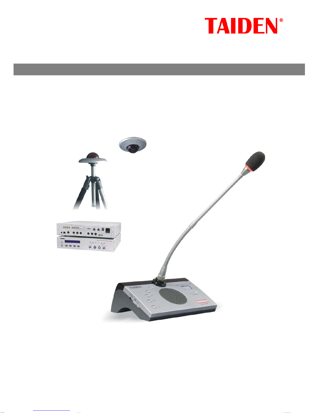
3.3 File Transfers ..........................................................................................6
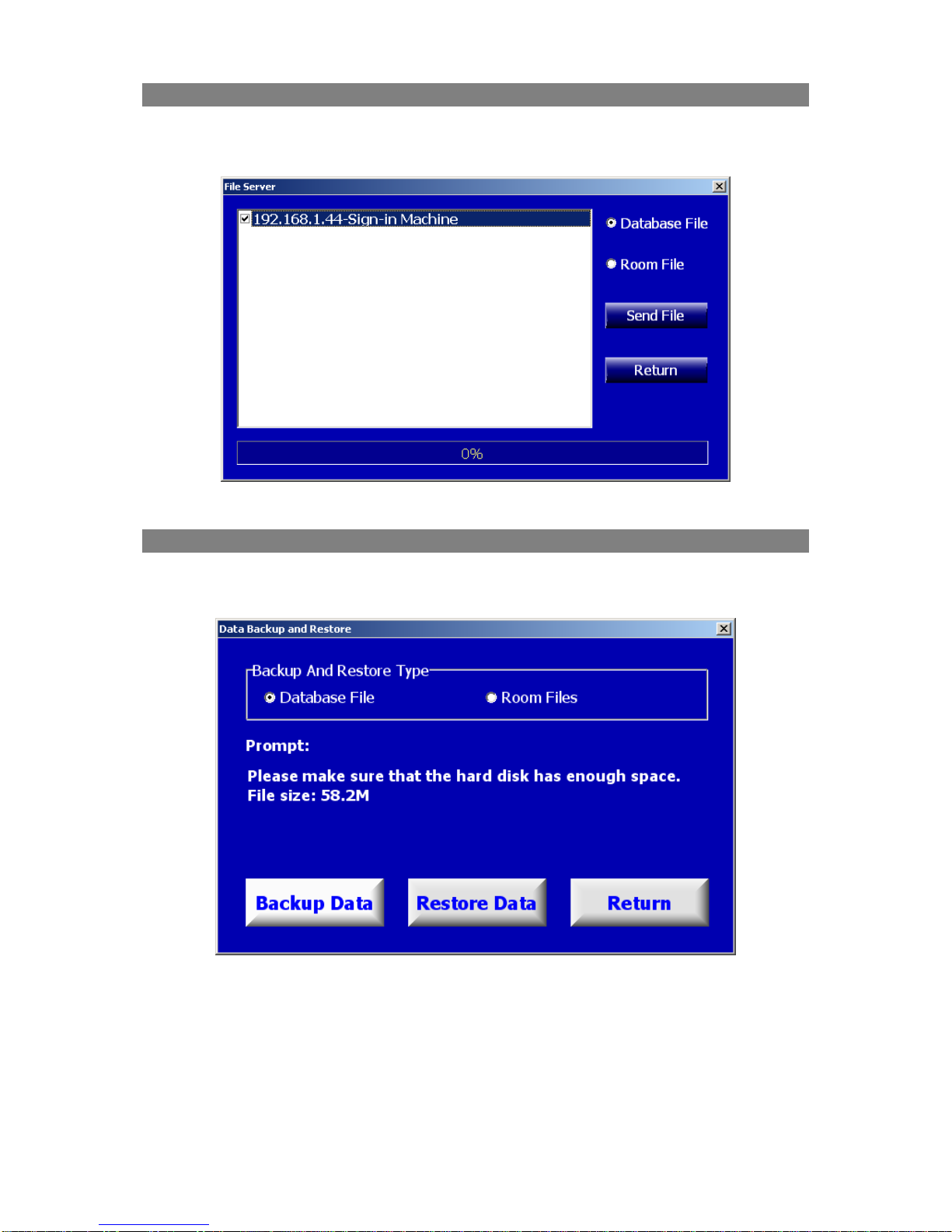
3.4 Backup and Restore.................................................................................6
Chapter 4. System Setup....................................................................7
4.1 Connect to CMU ......................................................................................7
4.2 Venue Designer.......................................................................................8
4.2.1 Venue Designer (Normal Edition)......................................................8
4.2.2 Venue Designer (Advanced Edition)................................................11
4.3 Screen Management..............................................................................18
4.3.1 Screen Project Setup.....................................................................18
4.3.2 Predefined Pages ..........................................................................19
4.3.3 Screen Event ................................................................................20
4.3.4 Alias.............................................................................................21
4.4 Video Tracking ......................................................................................22
4.4.1 Video Matrix .................................................................................22
4.4.2 Predefine Position .........................................................................23
4.4.3 Panorama Control .........................................................................25
4.5 Simultaneous Interpretation (S. I.)..........................................................26
4.5.1 Simultaneous Interpretation Channel Setup.....................................26
4.5.2 Booth Setup..................................................................................27
4.6 Short Message.......................................................................................28
4.7 Unit Management..................................................................................29
4.7.1 Unit Setup....................................................................................29
4.7.2 Unit Arrangement..........................................................................30
4.8 User Management..................................................................................32
4.9 IP Management.....................................................................................33
4.10 System Parameters..............................................................................34
4.11 CMU Parameters..................................................................................35
Chapter 5. Conference Preparation....................................................36
5.1 Select Meeting.......................................................................................36
5.2 Conference Information .........................................................................37
5.3 Proposal Information .............................................................................39
5.4 Agenda Information...............................................................................41
5.5 Delegate Information.............................................................................42
5.6 Participator ...........................................................................................45
5.7 Seat Arrangement..................................................................................46
5.8 Infrared Unit.........................................................................................49
I

II
Chapter 6. Conference Control..........................................................50
6.1 Hot Backup ...........................................................................................50
6.2 Start Meeting ........................................................................................50
6.3 End Meeting..........................................................................................50
6.4 Agenda Control......................................................................................51
6.5 Seat Sign-in ..........................................................................................52
6.6 Microphone Control................................................................................53
6.7 Topic and Voting ...................................................................................59
6.8 Video Switch .........................................................................................64
6.9 Screen Control.......................................................................................66
6.10 Short Message.....................................................................................66
6.11 Booth Management..............................................................................67
6.12 Unit Status..........................................................................................69
6.13 CMU Control Panel...............................................................................70
Chapter 7. Report system.................................................................71
7.1 Conference Information .........................................................................72
7.2 Proposal List..........................................................................................73
7.3 Delegate Information.............................................................................73
7.4 Seat Sign-in Report................................................................................74
7.5 Voting Result Report..............................................................................74
7.6 Summarizing Voting Result.....................................................................76
7.7 More Reports ........................................................................................77
Chapter 8. Assistant Functions..........................................................78
8.1 Record Management..............................................................................78
8.2 DVR Management..................................................................................80
8.3 Screen Monitor......................................................................................80
8.4 Voting Map ...........................................................................................81
8.5 Delegate Detail......................................................................................81
8.6 Conference Log .....................................................................................82
8.7 Discussion Information...........................................................................82
8.8 Edit shortcut button...............................................................................83
8.9 Lock Operation Interface........................................................................84
Chapter 9. Help...............................................................................84
Chapter 10. Software Hot-spare Dual Server......................................85

Chapter 1. Installation and Running
1.1 Running Environment
Hardware requirements: Pentium 4 2.0G/1G or higher.
Software requirements: Windows 2000/XP/Vista/Win7.
1.2 Installation
zCD Contents
The application software of HCS-5300 conference system.
zInstallation guide
Double click and run “Install.exe” on this CD.
1.3 Software Running
Once installation is completed, a shortcut named “DCS.exe” will appear on Windows desktop.
Double click it to run application, and the below login dialog is shown:
zMeeting Type: The default meeting type is “Base”, user can define its own meeting type,
different meeting types can have different configurations, including: database, system
parameters, etc. Different meeting types are used to adapt to different application
environments.
zThe default account is “admin”, and the password is null; the blue Language label at the right
upper side is used to change the language of application (click the label, and choose proper
language in the pop-up dialog box). Click “OK” button to enter the primary window, where
either administrator or user accounts can be created, as well as changing password. Refer to
section 4.8 for details.
1

Chapter 2. Primary Window
According to conference traditions, the primary window of the conference system application
software consists of separated parts:
File Management, System Setup, Conference Preparation,
Conference Control, Report System, and Assistant Functions.
The primary window of the
conference system software is shown below:
Figure: Primary Window of the Conference System
zFile Management: including Meeting Type, Import Delegate Data, File Transfers,
Backup/Restore;
zSystem Setup: including Connect to CMU, Venue Designer, Screen Management, Video
Tracking, Simultaneous Interpretation, Short Message, Unit Setup, Unit Management, User
Management, IP Authorization, System Parameters, CMU Parameters;
zConference Preparation: all preparatory work to be done before a conference, including
Select Meeting, Conference Information, Proposal Information, Agenda Information, Delegate
Information, Participator, Seat Arrangement, Infrared Units Management;
zConference Control: conference control functions in the meeting, including Hot-Backup,
Start Meeting, End Meeting, Agenda Control, Seat Sign-in, Microphone Control, Topic and
Voting, Video Switch, Screen Control, Short Message, Booth Management, Infrared Units Status,
CMU Control Panel;
zReport System: including Conference Information, Proposal List, Delegate Information, Seat
Sign-in Report, Voting Result, Summarizing voting result, More Reports, Report;
zAssistant Functions: some assistant functions including Record Management, DVR
Management, Screen Monitor, Voting Map, Delegate Detail, Conference Log, Discussion Report,
Edit Shortcut Button, Lock Operation Interface;
A detailed description of each module is presented in the last sections of this document.
2

Chapter 3. File Management
Including Meeting Type, Import Delegate Data, File Transfers, Backup/Restore.
3.1 Meeting Type
Figure: Meeting Type
Importing Style:
zCreated From Original Database: create an empty database;
zCreated From List Selected Database: create the same type of database according to the
selection from the left side list;
Operation:
¾Create Meeting Type:
Select importing style, and input meeting type name and click “Save”.
¾Delete Meeting Type:
Select an existing meeting type, right click on it, and select “Delete Meeting Type”.
¾Rename Meeting Type:
Select an existing meeting type, right click on it, select “Rename Meeting Type”, and input new
meeting type name.
New created meeting type can be selected when log on.
3

3.2 Import Delegate Data
Import delegate information from excel or text file. Delegate information includes: Number, Name,
Gender, Team, Group, Company, Department, Title, Clan, Seat, Photo, Presidium, etc.
Figure: Import Delegate Data
The left side is a delegate type option, including formal delegate, nonvoting delegate, guest,
audience, and staff. The right side is the operation dialog box, including file path, photo path,
process indication, and operation buttons.
Operation:
1. Select delegate type;
2. Click “Browse” to select the delegate information file;
3. Click “Browse” to select a directory containing delegate photos;
4. Click “Setup” to setup parameters:
Figure: Setup Parameter
Parameters includes: Fields configuration, Photo name Format configuration, Number offset.
zFields configuration: including Number, Name, Gender, etc., pitch on fields for import;
zPhoto name configuration: photo file name format;
zNumber offset: to avoid overwriting existing delegate data, imported delegate number will be
offset automatically according to this parameter;
4

5. Import: use of this function will delete all existing delegate data and import all new data from
excel or text file.
6. Update Import: use of this function will not delete existing delegate data and just import new
delegate data or update original delegate data from excel or text file.
Note: photo format supported including bmp, jpg, jpeg, gif, png, tif, tiff;
Excel format of delegate data for import:
Figure: Example of Delegate Data in Excel File
Text format of delegate data for import:
Figure: Example of Delegate Data in Text File
Note: Use “Tab” as list separator.
5

3.3 File Transfers
Use this function to update automatically data files from the server to the sign-in machine or the
backup server.
Figure: File Transfers Interface
3.4 Backup and Restore
Backup/Restore are used to backup conference data from the database into a folder or to restore
conference data from a folder into the database.
Figure: Back and Restore
zBackup And Restore Type: data type to backup/restore, including database file and room files;
zBackup Data: backup data from the database into a folder;
zRestore Data: restore data from a folder into the database;
Note: meeting type should be consistent with the current meeting when restoring data from a
folder;
6

Chapter 4. System Setup
Including Connect to CMU, Venue Designer, Screen Management, Video Tracking, Simultaneous
Interpretation, Short Message, Unit Management, User Management, IP Authorization, System
Parameters, CMU Parameters;
Figure: System Setup
4.1 Connect to CMU
Figure:ConnectToCMU Figure:LookingforCMUbyBroadcast
The system software connects to and communicates with the CMU. The IP address of the CMU
should be set up manually prior to the meeting. Or, looking for IP address via broadcast by setting
broadcast IP address as 255.255.255.255.
Note: the IP address of the CMU can be found through the CMU menu operation.
7

4.2 Venue Designer
Venue designer: the venue designer is the reproduction of the actual layout of the conference
venue in the form of a conference venue file (CVF). Its extended filename is .trm. The facilities
such as seat arrangement (i.e. both arrange seat and Unit Arrangement), entrance sign-in (access
control), seat sign-in, and microphone control shall use the conference venue file to perform
normal operation. The venue designer has two versions:
normal edition
and
advanced edition
; both
can carry out venue design; the advanced edition provides all capabilities of the normal edition plus
additional powerful and convenient functions. It is especially suitable for the design of large/
medium conference venues.
4.2.1 Venue Designer (Normal Edition)
The initial interface of the venue designer (Normal edition) is as in the figure below:
The functional buttons on the toolbar are:
New: create a new CVF (conference venue file);
Open: open an existing CVF;
Save: save CVF;
Save as: save current CVF as another;
Save as image: save current CVF as an image file;
Print: print the conference venue image;
Configuration: reconfigure the current CVF;
Advanced: switch to advanced edition;
Exit: exit venue designer.
8

Design conference venue
The procedure to create a CVF by the Venue Designer (Common edition) is as follows:
Create a new CVF
Click “New” button in the toolbar, and the dialog box of meeting room configuration appears as
shown in the figure below:
Figure: New Meeting Room
The background color, room size, and other related parameters (i.e. background image,
microphone number and number per line, etc) are available. Click “OK” to create the new CVF.
Parameters can be changed later through the
“Configuration”
menu on the toolbar. Or right click on
the venue and select
“Configuration” in
the pop-up menu or press
F5
on the keyboard to enter the
meeting room configuration interface.
Adjust layout
After clicking
“OK”
in the previous step, the operator can arrange the microphones based on the
actual layout of the venue by simply drag-and-drop the microphone icons to the desired positions in
the window (figure below). When the design is finished, click the
“save”
button to save the current
design.
9

Save CVF
Don’t forget to save the CVF when the design is completed by clicking the “save” button. If it is the
first time you save a new CVF, select the path and the input filename in the pop-up dialog box.
Then click “OK” to save and exit.
Special hint:
The CVF shall be saved in the “Rooms” folder in the main install directory of the
application to make it available for creating new conference information. The filename of the saved
CVF is the name of both the corresponding conference venue and the option of the drop-down list
box in the Conference Information interface.
10

4.2.2 Venue Designer (Advanced Edition)
The initial interface of the venue designer (Advanced edition) is as in figure below:
The functional buttons for file operation (bitmap buttons) and object operation (buttons below
bitmap buttons) are in the toolbars at the upper side. The functions are also available in the file
right-click pop-up menu. Moreover, the
Object Properties
dialog box is floating on the window for
quick changes of the properties of the current object group.
1. Operation menu
(1) File operation menu
New: create a new CVF (conference venue file);
Open: open an existing CVF;
Save: save a CVF;
Save as: save current CVF as another;
Save as image: save current CVF as an image;
Print: print conference venue image;
Configuration: reconfigure current CVF (background color, room size, and so on);
Normal: switch to normal venue designer;
Exit: exit venue designer.
(2) Object operation menu
Define object: open
Define object
dialog box, and its usage is given in the following section;
Add object: add new object into current meeting room;
Offset: globally offset all objects in current venue in both horizontal and vertical direction;
Object properties: Show/Hide
Object Properties
dialog box;
Check object ID: Show/Hide
Check Object ID
dialog box;
Copy: copy the selected object(s);
Cut: cut the selected object(s);
11

Paste: paste object(s);
Delete: delete selected object(s);
Undo: undo previous operation;
Redo: redo previous operation.
2. Object properties instruction
The
Object Propertie
s dialog box is as figure above, and it contains:
Group Name: define the name shown in the object list on the left side;
Object Name: select object name for current object group in the combo box; user can input the
name in textbox directly, if the name is not existing, the textbox turns red;
Object ID: define the object ID shown in
Seat Arrangement
and
Unit Arrangement
; while if it has
left null, the object will not be arranged in neither;
Caption: the caption displayed on the object;
Font Name: the font of caption;
Font Size: the font size of caption;
Status: select the initialized status of the group (6 states available);
Radian: set the radian of the group;
Start Index: set the start index of the object group;
Count: set the total number of the units in object group;
Increment: set the increment of numbering in the group;
Back color: set the initialized background color of the group; if “Transparent” is checked, the
initialized background color is disabled;
Start coordinate: set the start coordinate of an object/object group;
End coordinate: set the end coordinate of an object/object group.
3. Design a meeting room
This chapter describes the procedure of creating a CVF through the Venue Designer (Advanced
edition).
(1) Create a New CVF
Click “New” on the toolbar, and the
Meeting Room Configuration
dialog box pops up:
12

The background color, room size, and other meeting room parameters (i.e. background image, line
number and number per line, etc.) are also configurable. Click “OK” to create a new CVF, These
parameters can be changed later through the
“Configuration”
menu on the toolbar.
Notes: The comparison of the Meeting Room Configuration menus
(2) Define object
After the creation of a new CVF, the user can add objects and modify the properties of the objects
in the
“Define object”
dialog box (as in the figure below). The Venue designer has also some
customized common-used objects as default.
In the left textbox: a) a list of the customized objects, and b) the
“Add”
and
“Delete”
button - used
to add and remove objects to/from the list respectively. On the right side the related information of
the selected object is displayed, including object name, image path, and images in different states,
etc.
13

Figure: Define Object
The functions of these items are:
Object Name: specify the name of the object/object group;
Image path: specify the directory path of the status images of the object selected. The default
path is “Rooms” folder in the main directory path of the application. It is recommended saving
these images in the default path (i.e. "$AppPath$\Rooms" in the combo box);
Image0/Not Assigned: 0-state image and the image when the seat isn’t assigned;
Image1/Not Signed-in: 1-state image and the image when the delegate assigned to the seat
hasn’t signed in;
Image2/Signed-in: 2-state image and the image when the delegate assigned to the seat has
signed in;
Image3/Mic.: 3-state image and the image while the microphone of the corresponding seat is
OFF in microphone control mode;
Image4/Applying: 4-state image and the image while the microphone of the corresponding seat
is applying in the microphone control mode;
Image5/Speaking: 5-state image and the image while the microphone of the corresponding seat
is speaking in the microphone control mode.
Image6~10/Vote Result1~5: vote result state image in vote seat map.
After understanding the meanings of each status image, the user can choose appropriate images
for each state by clicking the ellipsis button following each textbox.
Special note:
cSince the image size of a group is determined by the size of “Image0”, user should pay special
attention to the size of this image. It is recommended that all other images have the same size as
image0, otherwise they will be resized to the size of image0 when the size is larger than image0.
It’s strongly recommended using images of identical size for the same object group.
14

dIf an object is a label or background, only image0 is necessary.
eVisible characters: if the size of the image is less than 30x30 pixels, no caption will be visible on
the image, neither will the delegate name be visible in
Seat Arrangement
.
fTransparency: if the initialized background color is set to transparent, the transparent area of the
object is transparentized; otherwise, the transparent area is substituted by the initialized
background color.
When the object group is set to transparent, the transparent area of each state image of the object
group shall be identical, or the desired effects won’t be seen.
About the transparent area: the area is a collection of elements with the same color as the element
in the lower left corner of an image. Generally, the transparent area can be set by specifying the
color in the corner to the same as the desired area through drawing tools (such as Windows Paint,
etc); whereas if no transparent effects are needed, just set the color of the corner element to the
color different from any colors in the image.
(3) Add object
After defining the object, it will be available in the
Select Object
dialog box list (figure below). Click
Add Object in the toolbar to open the dialog box.
The operator is now able to choose the object and to add it into the CVF.
(4) Object properties
Select an object in the current CVF, and its properties are filled in the
Object Properties
dialog box
(Click
Object Properties
button to open); meanwhile, user can change values in the dialog box.
Make sure to click “OK” button or to press
Enter
key to apply these changes.
Here are some explanations of these properties:
Object ID: It is the unique identification in seat arrangement for the unit. The default name is
"1Row$NUM$": “1Row” shall be replaced by an intelligible symbol according to the actual
requirement, such as numbers (1, 2, 3…), letters (A, a, B…) and strings (front, back, and so on),
etc. “$NUM$” is the index mark decided by start index, count and increment of the object group. In
the figure below, the group’s start index is 1, count is 10, and increment is 1; therefore the
“$NUM$” of the first unit in the group is 1, while the second is 2 (1+1), and so on.
Another two options - “$0NUM$” and “$00NUM$” - which stand for “0” or “00” to be prefixed to the
“$NUM$”; under this choice, if the start index is “1”, the actual result will be “01” or “001”
respectively (The “1”, “01” and “001” aren’t the same but stand for three different object IDs).
Note: if the object group is used as background, labels, and illustrations, etc, the object ID should
remain null.
15

Caption: The setup is similar to the "Object ID".
Status: Generally, the default value is 0 or 3; it can be set to another if needed.
Radian: Arrange the object group in an arc form according to the specified value.
Transparent: If checked, the transparent area is shown transparently; otherwise, the selected
background color is shown.
(5) Check object ID
Since the object ID is the unique identification of the object in the
Seat
Arrangement,
Venue designer provides
Check Object ID
facility to
ensure the uniqueness. Click
“Check Object ID”
in the toolbar to open
this facility, as shown in the right figure; click
“Check”
to start, if there
are duplicate IDs, the duplicate IDs are listed in the dialog box, then
double click
“object belong to”
to localize the object. If there are no
more duplicate IDs, a message box prompting
“Object ID is exclusive”
is
shown:
Note: This tool is only used to test object ID, not test the caption, so for
future convenient operation, caption should be changed together with
the change of object ID.
(6) Object copy, cut, paste, and delete
For objects of the same type, using
“Copy”
,
“Cut”
, and
“Paste”
buttons will be useful. Note that the
properties of the copied object and the pasted object are identical, so do not forget to change the
ID of the pasted object. Use the
“Delete”
button to delete the unused object.
16
Other manuals for HCS-5300
1
Table of contents
Other Taiden Conference System manuals

Taiden
Taiden HCS-4800 Series User manual

Taiden
Taiden HCS-5335 Series User manual

Taiden
Taiden HCS-4100/50 Series User manual

Taiden
Taiden HCS-5300MA/80 User manual

Taiden
Taiden hcs-8300 User manual

Taiden
Taiden HCS-8600 Series User manual

Taiden
Taiden HCS-4800 Series User manual

Taiden
Taiden HCS-3600 Series User manual

Taiden
Taiden TES-5680 Series User manual

Taiden
Taiden HCS-5300 User manual