T&R Z-OVR Operating instructions

1
OPERATING AND MAINTENANCE MANUAL
Product: Cable Impedance Test System
Type: Z-OVR
Software version 1.04
DESIGNED AND MANUFACTURED BY:
T & R Test Equipment Limited
15-16 Woodbridge Meadows, Guildford, Surrey, GU1 1BJ, United Kingdom
Web: www.trtest.com

2
GENERAL SAFETY STATEMENT
CAUTION
The following safety precautions should be reviewed to avoid injury to the user and damage to the product
(and other products connected to it). To avoid potential hazards only use this product as specified.
Only suitably qualified personnel should use this equipment. Servicing of this product should
only be carried out by suitably qualified service personnel.
To Avoid Fire Hazards and Personal Injury
Use the correct power supply lead. Only use a suitably rated and approved power supply lead for
the country of use.
Ensure that systems that the unit is to be connected to are isolated from the supply and earthed.
Do not connect and disconnect leads whilst outputs are switched on. Breaking the output circuit with
current flowing may cause potentially fatal arcing.
Ensure that the product is grounded. To avoid electric shock, it is essential that the grounding
conductor is connected to the earth ground. An additional earth terminal is provided on the unit that
should be connected to a local earth. Ensure that the unit is properly grounded before making any
connections to inputs or outputs.
Terminal ratings must be observed to prevent fire hazards and risk of injury to the operator. Consult
the product manual for ratings information before making connections to any terminal.
It is ESSENTIAL to consult the product manual for rating information before making any connection
to a terminal or terminal group marked with a warning triangle.
Only use fuses of a type and rating specified for this product.
Do not operate the unit out of its case or with any covers or panels removed.
Do not touch exposed connections and components when power is present.
Do not operate the product if any damage is suspected. Refer the unit to qualified service personnel
to be checked.
Do not operate the unit in wet or damp conditions.
Do not operate the unit in an explosive atmosphere.
Do not operate the unit if there is the possibility of lightning strikes on the line under test or connected
lines.
If any further queries occur regarding the usage and maintenance of the equipment detailed
in this manual, please refer these to the supplier of the equipment in the first case or to the
manufacturer, T & R Test Equipment Limited.

3
SAFETY TERMS AND SYMBOLS
The following safety symbols appear on the equipment:
CAUTION/WARNING – Refer to manual
Mains off
Mains on
The following safety symbols appear in this manual:
CAUTION
This action or procedure may be dangerous if not carried out
correctly and may cause damage to the equipment or
connected equipment.
WARNING
This action or procedure may cause injury or death to the
operator or other personnel if not carried out correctly using
applicable safety procedures.
! Note This is useful information that may make testing easier, help
in interpretation of results or prevent confusion.


5
CONTENTS
1. DESCRIPTION OF EQUIPMENT 7
1.1 Panel layout and functions 8
1.1.1 Control unit 8
1.1.2 Output unit 10
1.1.3 Display 12
1.1.4 Warning messages 12
1.2 Installation 13
1.2.1 Environment 13
1.2.2 Supply requirements 13
1.2.3 Cables 14
1.2.4 System connections 17
1.2.5 Overload protection 18
1.3 Functions 18
1.3.1 Output 18
1.3.2 Metering 19
1.3.5 Result storage 23
2. THEORY OF OPERATION 26
2.1 Kelvin connection 26
2.2 Impedance testing 27
2.3 Phase reversal to avoid interference 28
3. OPERATION 29
3.1 Setting up 29
3.1.1 System connections 30
3.1.2 Line connections 30
3.2 Testing 33
3.3 After Testing 34
4. MAINTENANCE 35

6
4.1 Output Control Brushes 35
4.2 Removal of the Z-OVR from Case 35
5. STANDARD ACCESSORIES 37
5.1 Spare Fuses Supplied: 37
5.2 Standard Accessories Supplied: 37
6. OVERALL PERFORMANCE SPECIFICATION 39
6.1. Insulation Resistance at 1000V DC 39
6.2. Applied Voltage Test 39
6.3. Accuracy of Instruments 39
6.3.1 Current metering 39
6.3.2 Voltage metering 39
6.3.3 Phase metering 39
7. REVISION 41

7
1. DESCRIPTION OF EQUIPMENT
The Z-OVR is a line/cable impedance measurement system for high voltage ac systems. The
impedance of the line is measured by injecting a current and measuring the magnitude and
phase angle of the voltage developed across the line. The resistance and reactance of the line
are calculated from these results and displayed. The system uses a 4-wire measurement with a
Kelvin connection to the line under test to eliminate measurement errors due to voltage drops
in the leads.
The unit has the facility to store test results to a USB memory key.
The system consists of a separate control unit containing all metering and control functions and
an output unit that provides the high current output and isolation of measured voltages. All
connections to the line are made via the output unit.
The system is supplied with three overhead line Kelvin clamps, one earth Kelvin clamp, one
earth lead and all interconnecting and supply leads.
Three outputs are provided on the output unit (75V 80A, 150V 40A and 300V 20A) to allow a
wide range of lines to be tested.
.
WARNING
The Z-OVR system must only be used on ‘dead’ systems (i.e. no externally
supplied voltages are present on the test object) with safety earths applied.
Extreme caution must be applied due to the possibility of induced voltages from
other energised circuits. Under no circumstances connect a PCU1 to a live system
or lines without earths applied.
WARNING
Under no circumstances use any of the leads supplied with the unit as earthing
equipment for high voltage lines or cables. Approved earthing equipment must be
used in accordance with accepted working practices before connections can be
made between the line and Z-OVR.

8
B C D E
S
T
F
G
H
I
J
K
L
M
N
O
P
Q
R
1.1 Panel layout and functions
1.1.1 Control unit
Figure 1.1 Z-OVR front panel
A

9
ITEM FUNCTION
A Output unit metering connection Metering/control connection to output unit
B Output circuit breaker Protection for control unit output
C Output unit power connector Power supply to output unit
D Mains input switch/circuit breaker Supply isolation switch and protection
E Mains inlet connector Mains supply connection
F Earth Terminal Terminal for optional connection to local
earth for enhanced safety
G Fuse Fuse for metering and control circuits
H Power indicator Supply on indicator
I RS232 connector Serial connection for PC/printer connection
J Main output control Sets output current
K Output off button Switches output off. Illuminates green to
show that output is off.
L Output on pushbutton Switches output on. Illuminates red to show
that output is on.
M Adj. digital pot Control to select values for result storage
N Impedance measurement select Selects calculated value to display-
impedance, frequency or harmonics
O Store pushbuttons Pushbutton switches for store result and
selection
P Liquid crystal display Shows current, voltage and calculated values
Q Voltmeter range select Selects voltage measurement range
R Store result select Controls result storage functions
S Ammeter range select Selects ammeter range
T USB sockets USB sockets for keyboard and memory key

10
A B
C
D
E
F
G
H I
J
1.1.2 Output unit
Figure 1.2 Output unit front panel

11
ITEM FUNCTION
A Output commoning block Allows three phase cables to be connected
together for parallel measurement. All four
terminals are connected together.
Note: push connector to release before
pulling to remove plug from socket.
B Voltage input sockets Voltage measurement input
C Voltage input fuses Fuses to protect voltage input
D 300V 20A output socket Highest voltage, lowest current output.
Note: push connector to release before
pulling to remove plug from socket.
E 150V 40A output socket Mid range current output.
Note: push connector to release before
pulling to remove plug from socket.
F 75V 80A output socket Lowest voltage, highest current output.
Note: push connector to release before
pulling to remove plug from socket.
G Z-OVR metering connection Metering/control connection to control unit
H Power connector Power supply from control unit
I Protective earth terminal Connect to low impedance local earth
J Common output socket Common connector for output current

12
1.1.3 Display
The Z-OVR display simultaneously shows the injected test current, measured voltage and one
of a number of other parameters depending on the position of the IMPEDANCE switch. For full
details see section 1.3.4.
Output current Phase angle Voltage input
Impedance Reactance
Output current Phase angle Voltage input
Frequency of measured voltage
Output current Phase angle Voltage input
Harmonic value 1 Harmonic value 2
Output current Phase angle Voltage input
Harmonic value 1 Harmonic value 2
Figure 1.3 Z-OVR metering values
1.1.4 Warning messages
Figure 1.4 Over-current trip warning message
When an over current or duty cycle trip occurs, the green OFF pushbutton must be pressed to
clear the trip condition.
Figure 1.5 Duty cycle trip warning message
I ¢ V
10.00A
90.0°
1.00V
IMPEDANCE
Z=100.0m©
X=100.0m©
I ¢ V
10.00A
90.0°
1.00V
FREQUENCY
50.00Hz
I ¢ V
10.00A
90.0°
1.00V
Voltage Harmonics
1: 200.0V
2: 0.0%
I ¢ V
10.00A
90.0°
1.00V
Current Harmonics
1: 50.0A 2: 0.0%
Output tripped
Press Green to Reset
Duty Cycle Trip
Press Green to Reset
Impedance
Frequency
Harmonic V
Harmonic I

13
Caution
Allow the unit to cool for the rated off time for the main output after a duty cycle trip
Figure 1.6 Unit over temperature warning message
Caution
After an over temperature trip, the unit will automatically reset when the temperature
falls to an acceptable level. If the unit is over temperature, switching the unit off and
back on will not clear the message – the unit must be allowed to cool.
1.2 Installation
Caution
The Z-OVR
control units and output unit are heavy. Avoid lifting where possible.
Ensure that two people are used to lift the units and that appropriate manual
handling techniques are used.
1.2.1 Environment
Z-OVR is designed for use in indoor industrial and electrical substation environments.
Maximum altitude: 2000m
Temperature: 0°C to 45°C operating
-20°C to 60°C storage
Relative humidity: 90% non-condensing
Protection rating: IP20
1.2.2 Supply requirements
230V±10% 50/60Hz 1 phase 6.5kVA.
The unit is supplied fitted with a 32A CEE plug. If it is necessary to fit a different plug, the supply
cable has the following core colours:
Earth Green/yellow
Live Brown
Neutral Blue
The equipment must be earthed through the mains supply. In addition, the output unit must be
earthed using the supplied earth lead to a suitable low impedance local earth (such as the base
of a transmission tower).
The earth terminal on the control unit should be connected to a low impedance local earth if the
supply earth is suspect.
Caution
Ensure that the unit is connected to an appropriate supply by a suitably rated
connector and that the system is adequately earthed.
Over Temperature
Press Green to Reset

14
1.2.3 Cables
The following cables are supplied with the Z-OVR system.
Supply/interconnection cables Length Purpose
Mains supply cable 5m Supply to control unit
Power interconnection cable 5m Connects output unit to control unit
Metering interconnection cable 5m Connects output unit to control unit
Earth cable 10m Connects output unit to safety earth

15
Output cables Length Purpose Rating
Output cable phase A
(red)
12mm² current injection
terminated in 6mm
connector
6mm² voltage sense
terminated in 4mm
shrouded plug
10m Duplex lead fitted with Kelvin
clamp for overhead line
connection.
Max conductor size 80mm
diameter.
80A
CAT I
300V*
Warning
Output cable phase B
(yellow)
12mm² current injection
terminated in 6mm
connector
6mm² voltage sense
terminated in 4mm
shrouded plug
10m Duplex lead fitted with Kelvin
clamp for overhead line
connection.
Max conductor size 80mm
diameter.
80A
CAT I
300V*
Warning
Output cable phase C
(blue)
12mm² current injection
terminated in 6mm
connector
6mm² voltage sense
terminated in 4mm
shrouded plug
10m Duplex lead fitted with Kelvin
clamp for overhead line
connection.
Max conductor size 80mm
diameter.
80A
CAT I
300V*
Warning
Output cable ground
(green)
12mm² current injection
terminated in 6mm
connector
6mm² voltage sense
terminated in 4mm
shrouded plug
10m Duplex lead fitted with Kelvin
clip.
Max jaw opening 27mm.
80A
CAT I
300V*
Warning
*voltage
ratings
Warning
The voltage ratings shown relate to the cable and 4mm/6mm connectors to
connect to the output unit. The cables are terminated in un-insulated clamps for
connection to lines that must NOT be handled whilst the output is on.
Make all connections to the test object with the supply off (supply switch in the
off position) and the cables unplugged from the output unit.

16
The phase clamp connections supplied with the unit are designed for connection to cylindrical
conductors on overhead lines. An optional alternative set of phase leads is available for
connection to other types of conductors and terminals using Kelvin clips as on the earth lead.
Phase A Kelvin clip lead part number:
AX136-0007
Phase B Kelvin clip lead part number:
AX136-0008
Phase C Kelvin clip lead part number:
AX136-0009

17
1.2.4 System connections
Figure 1.7 System connections

18
1.2.5 Overload protection
Location Protection
Mains supply Hydraulic-magnetic circuit breaker
Control unit output Hydraulic-magnetic circuit breaker
Control unit control/metering T4A HRC 32mm fuse
Voltage input 2xT250mA HRC 32mm fuses
1.3 Functions
1.3.1 Output
The output has three ranges. The highest currents are available on the lowest voltage outputs.
When testing, start with the lowest output voltage output. If the required test current cannot be
achieved (because the impedance of the line is high) use a higher voltage output.
Output unit Open Circuit
Voltage
Continuous
current
Intermittent current
5 min on/
15 min off
Maximum
current
NLU75/80
75V 40A 80A 100A*
150V 20A 40A 40A
300V 10A 20A 20A
*100A available for short periods
Each output is rated for a continuous current and for higher intermittent currents. The maximum
ON time for intermittent currents is enforced by the unit, and the output will be switched off if the
rating is exceeded. The display will then show the following message until the green OFF button
is pressed to clear the trip condition:
Figure 1.8 Output tripped
!
NOTE
If the metering cable is not connected between the control unit and the external
output unit, the ammeter will not function, and the output will not switch on when the
output ON push-button is pressed. The metering cable between the control and
external output unit acts as an interlock circuit.
Output tripped
Press Green to Reset

19
1.3.2 Metering
The Z-OVR is fitted with a true rms ammeter and voltmeter with hold facility.
1.3.2.1 Ammeter ranges
Figure 1.9 Ammeter
Four true rms current metering ranges are provided. The range is selected using the AMMETER
switch on the control unit. A current trip is set at 105% of the full scale of the range.
Ammeter range
Metering full
scale Resolution Accuracy Trip current
2A 2.000A 0.001A ±1%rdg+5d 2.1A
10A 10.00A 0.01A ±1%rdg+5d 10.5A
20A 20.00A 0.01A ±1%rdg+5d 21A
100A 100.0A 0.1A ±1%rdg+5d 105A
1.3.2.2 Voltmeter ranges
Figure 1.10 Voltmeter
Three true rms voltage metering ranges are provided. The range is set using the VOLTMETER
switch on the control unit. The voltage measuring input is isolated by a switched range VT. The
VT provides safety isolation from the line under test, but has a relatively low input impedance
on the 10V and 30V ranges. Do not use the 10V or 30V range with test currents of less than 5A
to maintain accuracy.
Caution
Ensure that the maximum voltage applied to the voltage input does not exceed the
range selected. Fuses are provided on the input to protect the VT. If the voltage
for the range selected is too high the fuses on the VT input will blow.
I ¢ V
10.00A
90.0°
1.00V
IMPEDANCE
Z=100.0m©
X=100.0m©
I ¢ V
10.00A
90.0°
1.00V
IMPEDANCE
Z=100.0m©
X=100.0m©

20
Voltmeter range Resolution Accuracy Input impedance
10.00V 0.01V ±1%rdg±5d ~1k
30.00V 0.01V ±1%rdg±5d ~1k
300.0V 0.1V ±1%rdg±5d ~50k
Accuracy
note
Always Use the 300V metering range if the test current is less than 5A.
1.3.2.4 Phase angle measurement
Figure 1.11 Phase angle
The phase angle between the voltage and current is calculated by taking an FFT (Fast Fourier
Transform) of both the current and voltage and calculating the phase difference between the
fundamental components.
The phase angle of the current is measured relative to the voltage. A phase angle of -90° would
signify that the current is lagging the voltage by 90° (an inductive load). A phase angle of +90°
would signify that the voltage is leading the current by 90° (a capacitive load).
Range Resolution Accuracy
-179.9º - 180.0º 0.1º ±1º
I ¢ V
10.00A
90.0°
1.00V
IMPEDANCE
Z=100.0m©
X=100.0m©
Table of contents
Other T&R Test Equipment manuals
T&R
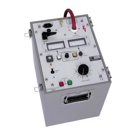
T&R CU-Ps Operating instructions
T&R
T&R KV30-40 Operating instructions
T&R
T&R 200A-3PH mk2 Operating instructions
T&R
T&R PCU2 mk5 Operating instructions
T&R
T&R KV mk2 Series Operating instructions
T&R
T&R PT18-10 mk2 Operating instructions
T&R
T&R KV5-100 mk3 Operating instructions
T&R
T&R 200A-3PH Operating instructions
T&R
T&R PT30-10 mk2 Operating instructions
T&R
T&R PT30-10 Operating instructions
