manuals.online logo
Brands
  1. Home
  2. •
  3. Brands
  4. •
  5. T&R
  6. •
  7. Test Equipment
  8. •
  9. T&R PT15-10s Operating instructions

T&R PT15-10s Operating instructions

OPERATING AND MAINTENANCE MANUAL
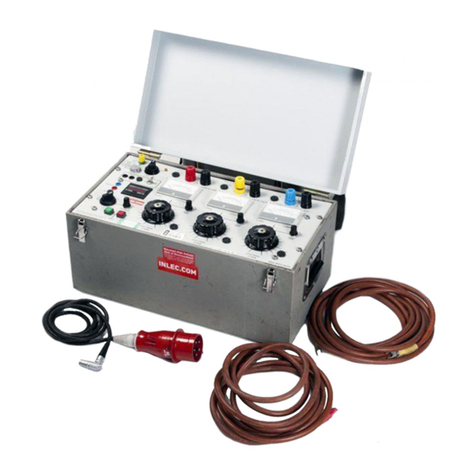
Product: High Voltage DC Cable Test Set
Type: PT15-10s
DESIGNED AND MANUFACTURED BY:
T & R Test Equipment Limited
15-16 Woodbridge Meadows, Guildford, Surrey, GU1 1BJ, United Kingdom
Telephone: 01483 207428 e-mail: [email protected]
Fax.: 01483 511229 Web: www.trtest.com
TRUSTED & RELIABLE
2
3
GENERAL SAFETY STATEMENT
The following safety precautions should be reviewed to avoid injury to the user and damage to
the product (and other products connected to it). To avoid potential hazards only use this
product as specified.
Only suitably qualified personnel should use this equipment. Servicing of this product should
only be carried out by suitably qualified service personnel.
Hazardous voltages and currents are present on the outputs of this unit.
To Avoid Fire Hazards and Personal Injury
Use the correct power supply lead. Only use a suitably rated and approved power supply lead
for the country of use.
Ensure that systems that the unit is to be connected to are dead.
Do not connect and disconnect leads whilst outputs are switched on.
Ensure that the product is grounded. To avoid electric shock it is essential that the grounding
conductor is connected to the earth ground. If an additional earth terminal is provided on the
equipment that may be connected to a local earth. Ensure that the product is properly
grounded before making any connections to inputs or outputs.
Terminal ratings must be observed to prevent fire hazards and risk of injury to the operator.
Consult the product manual for ratings information before making connections to any terminal.
It is ESSENTIAL to consult the product manual for rating information before making any
connection to a terminal or terminal group marked with a warning triangle.
Only use fuses of a type and rating specified for this product.
Do not operate the unit out of its case or with any covers or panels removed.
Do not touch exposed connections and components when power is present.
Do not operate the product if any damage is suspected. Refer the unit to qualified service
personnel to be checked.
Do not operate the unit in wet or damp conditions
Do not operate the unit in an explosive atmosphere
If any further queries occur regarding the usage and maintenance of the
equipment detailed in this manual, please refer these to the supplier of the
equipment in the first case or to:
T & R Test Equipment Limited
4
5
CONTENTS
1. Description of Equipment
2. Operation of Equipment
3. Maintenance Instructions
4. Standard Accessories
5. Overall Performance Specification
6. Revision
6
7
1. DESCRIPTION OF EQUIPMENT
1.1 Electrical Specification
1.2 Output Voltage Control
1.3 Overload Protection
1.4 High Voltage Output Cables
1.5 Metering
1.6 Automatic Earthing
1.7 Manual Earthing Using DP20 Discharge/Earthing Probe
1.8 Construction
1.9 Storage
8
9
1.1 Electrical Specification
1.1.1 The supply voltage for the equipment is 240/115V, single phase, 50/60Hz. Each
input will tolerate the following voltage variation:
240V ± 10%
115V +10% and -6%
1.1.2 The maximum power supply requirements will be 400VA.
1.1.3 The output voltage which is continuously obtainable from the equipment is:
a. 15kV DC negative with respect to earth
b. The maximum charging current from the equipment when charging a high
capacitance load will be 10 mA
c. The maximum currents available from the equipment are as the following
table:-
V supply kV DC mA DC R load C load
240V 15 0 500pF
““2.14 7M0.075F
““5.23 2.86M0.15F
““8.4* 1.78M0.15F
““10.00* 1.5M0.225F
115 “0 0.225F
““2.12* 7.07M0.225F
“11.5 6.00* 1.91M0.225F
“10.8 7.2* 1.5M0.225F
The above currents marked with an * are based on a duty cycle of 5 minutes “ON”
then followed by 15 minutes ‘OFF’ load. The load applied to the equipment is a
combination of R load and C load in parallel.
1.1.4 The earthy end of the high voltage output is connected to the earth system of the
equipment.
Note: There is a Voltage Dependent Resistor, internal connected between neutral & chassis.

10
1.2 Output Voltage Control
1.2.1 The output from the equipment is controlled from zero by means of a regulating
transformer.
1.2.2 The transformer is operated by means of a control knob which is located on the
right hand side of the instrument's front panel.
1.2.3 To increase the output voltage turn the control knob in a clockwise direction.
1.2.4 Note: The output can not be energised unless the regulator knob is set to zero,
thus operating the zero voltage interlock switch.
1.3 Overload Protection
1.3.1 The instrument is fitted with fast acting fuses which protect the incoming mains
supply to the unit. The rating of the fuses is as follows:
a. F3.15A for 240V operation
b. F5A for 115V operation
1.3.2 The outputs from the instrument are protected by means of a fast acting magnetic
overload relay which in turn controls an output contactor. The overload is set for
12 - 15 milliamperes.
1.4 High Voltage Output Cable
1.4.1. The high voltage output cable provided with the equipment are 5M long and are
terminated with a suitable connector allowing a good secure connection to the test
object. The cable type used is UR67M with a multi-stranded inner core. The
outer screen is connected via the high voltage plug to the ground connection on the
PT15-10s.
1.4.2. The high voltage plug is protected in transit by a plastic cover. The plastic cover is
attached to output cable by means of thick nylon cord.
1.4.3. The high voltage plugs used on the PT15-10s are fully de-mountable, thus allowing for
re-termination on site should the output cables become damaged.
11
1.5 Metering
1.5.1 The equipment is fitted with an output kilovolt meter which senses the high voltage
from the equipment. The output kilovolt meter has one range which is 0-15 kV dc.
1.5.2 The equipment is fitted with an output milliammeter which senses the output
current from the equipment. The output milliammeter has two ranges :-
0-10 milliamps dc 0-1 milliamps dc
The range change on the milliammeters is achieved by means of an non latching
push-button which is coloured white and located on the instrument's front panel.
The rest position is Range 1 and the activated position is Range 2.
1.6 Automatic Earthing
1.6.1 AUTOMATIC DISCHARGE/EARTHING
The automatic discharge system, which is fail safe, will discharge a maximum of
1.25 kilojoules at 15kv DC four times every hour. The contact surfaces of the
internal dump switches are made of very hard dissimilar metals to contain
contact burning and erosion.
12
1.6 Manual Earthing Using DP20 Discharge/Earthing Probe
1.6.1 Important:- DP20 Discharge/Earthing Probe
WARNING NOTICE
Under no Circumstances Must the Discharge/ Earthing
Probe be Used on Energised A.C. Distribution Systems.
Failure to Observe the Above Will Result in
Severe Damage to the Discharge Probe and, More
Importantly, Possible Fatal Injury to the Operator.
1.6.2 The Specification for DP20 Max. discharge voltage (kVdc) 20kVdc
Max. discharge capacitance 12F
Max. discharge energy 3.6kJ
Max. discharges per hour 4
1.6.4 Using DP20 with the PT15-10s
The DP20 is capable of discharging 3.6 kilojoules of stored energy at 15kV 4 times
every hour.
Red hand
guard
Resistor stack
5 metresclear silicon rubber covered
multistranded copper conductor.6mm2
Earth hook
1.6.3 DP20:- overall length = 530mm
13
1.8 Construction
1.8.1 The unit is housed in a grounded chassis which is completely screened. This chassis
is then housed in the main case which is made from a structurally reinforced plastic.
1.8.2 All accessories are housed in a separate carry bag.
1.8.3 All the controls for the equipment are located on the front panel together with all the
input and output sockets.
1.9 Storage
1.9.1. The PT15-10S when not in use must be stored in a dry environment, corrosion damage
may occur to the HV components if stored in damp environment.
1.9.2. Important:
If the unit is moved from a cold area to a warmer area condensation could form on the
HV components, this would greatly reduce the internal breakdown voltage.
If it is suspected that condensation may have formed the PT15-10S should not be used
until its temperature has stabilised and any condensation evaporated, this may take
many hours.
14
15
2. OPERATION
2.1 Supply Voltage Selection
2.2 Front Panel Control Functions.
2.3 Testing Procedures and Safety Precautions
16
17
2.1 Supply Voltage Selection
Disconnect the PT15-10s from the Mains Supply.
2.1.1 The supply voltage selector is located in the input socket module. The method of
selection is as follows:
a. Remove fuse drawer .
b. Remove and rotate fuse carrier until desired supply voltage is seen through
the fuse drawer window.
c. The PT15-10s is suitable for 2 different supply voltages as follows:
240V or 115V.
d. Replace fuse drawer once the desired voltage has been selected.
2.1.2 IMPORTANT!
Under no circumstances should the supply voltage selector be altered when the
equipment is energised.
ALWAYS ENSURE THAT THE SUPPLY VOLTAGE SELECTOR IS IN THE
CORRECT VOLTAGE POSITION BEFORE ENERGISING THE EQUIPMENT
18
2.2 Front Panel Control Functions
2.2.1 ITEM FUNCTION
Supply Switch To isolate both supply leads from the set.
ON/OFF
Supply on Lamp To indicate supply is connected to the set
and that supply fuse is healthy.
10 push-button Selects range for output milliammeter.
HV OFF illuminated Indicates HV output off when lit. Switches
push-button (Green) off HV output when pressed.
HV ON illuminated Indicates HV output on when lit. Switches
push-button (Red) on HV output when pressed.
Input module Selects either 240/115V supply voltages
houses mains fuse.
19
Figure 1 Front Panel Layout - PT15-10s
÷10
CABLE TEST SET TYPE PT15-10S
POWER ON
HV OUTPUT
ON OFF
INPUT 1ph 50/60Hz
240V 3A Ty pe F -- 115V 5A Type F
NEG
HIGH VOLTAGE
-kV.DC
-mA.DC
DANGER
EARTH
Negative kilovoltmeter
Milliamp meter ÷10 push-button
Power ON/OFF key switch
Output ON push-button
Output OFF push-button
Fused mains input module
Output voltage control
Power ON lamp
Negative Milliamp meter
Negative output socket
Earth terminal
& voltage selector
20
2.3 Testing Procedures and Safety Precautions: For Guidance Only
THE PROCEDURES SET OUT BELOW MUST ONLY BE CARRIED
OUT BY AUTHORISED PERSONNEL.
Local Health and Safety Regulations Must Be Observed.
2.3.1 SAFETY PRECAUTIONS:
a. Always ensure by means of a live line tester that the cable about to be tested is
not live. This applies both to old and newly installed cables and also to all phases.
b. The test area must be well signed "" DANGER H.V. TESTING "", or similar
wording at both ends of the cable.
c. The test area at each end of the cable must be roped off.
d. It is important for the safety of the operator and to protect the equipment that
an adequate ground connection be provided. The ground is normally connected
to the cable sheath. If the cable sheath is not earthed (this may occur on cables
which have just been installed) a temporary earth spike 0.5M long may be used.
However, this should be treated with caution, since the soil may have a high
resistivity
2.3.2 CONNECTION SEQUENCE:
See Figure 2
a. Connect earth lead between test object earth and PT15-10s earth terminal.
b. Connect discharge/earthing probe to the PT15-10s earth terminal. The earth
hook on the probe must now be placed on the test object terminal.
c. Connect the phases not being tested to earth.
d. Connect the HV lead to the negative output socket on the PT15-10s and to
the test object.
e. Ensure The Correct Supply Voltage Is Selected On The PT15-10s.
f. Connect the PT15-10s to mains supply.
g. Repeat The Procedure And Check That All Connections Are Secure
And That All Unauthorised Personnel Are Out Of The Test Area.
h. Remove the discharge/earthing probe

This manual suits for next models

1

Other T&R Test Equipment manuals

T&R PCU2 mk5 Operating instructions

T&R

T&R PCU2 mk5 Operating instructions

T&R TPT9000 Operating instructions

T&R

T&R TPT9000 Operating instructions

T&R Z-OVR Operating instructions

T&R

T&R Z-OVR Operating instructions

T&R PT18-10 mk2 Operating instructions

T&R

T&R PT18-10 mk2 Operating instructions

T&R KV5-100 mk3 Operating instructions

T&R

T&R KV5-100 mk3 Operating instructions

T&R 200A-3PH mk2 Operating instructions

T&R

T&R 200A-3PH mk2 Operating instructions

T&R KV30-40D mk3 Operating instructions

T&R

T&R KV30-40D mk3 Operating instructions

T&R KV mk2 Series Operating instructions

T&R

T&R KV mk2 Series Operating instructions

T&R KV6-80 Operating instructions

T&R

T&R KV6-80 Operating instructions

T&R KV30-40 Operating instructions

T&R

T&R KV30-40 Operating instructions

T&R PT30-10 Operating instructions

T&R

T&R PT30-10 Operating instructions

T&R CU-Ps Operating instructions

T&R

T&R CU-Ps Operating instructions

T&R 200A-3PH Operating instructions

T&R

T&R 200A-3PH Operating instructions

T&R PT30-10 mk2 Operating instructions

T&R

T&R PT30-10 mk2 Operating instructions

Popular Test Equipment manuals by other brands

PCE Instruments PCE-LOC 10 user manual

PCE Instruments

PCE Instruments PCE-LOC 10 user manual

Valeo ClimFill Maxi Use and maintenance manual

Valeo

Valeo ClimFill Maxi Use and maintenance manual

SEAWARD Electronic PAC3760 plus II operating instructions

SEAWARD Electronic

SEAWARD Electronic PAC3760 plus II operating instructions

WT PH 2066UK Installation operation & maintenance

WT

WT PH 2066UK Installation operation & maintenance

Alcolizer EC Calibration Station Service instructions

Alcolizer

Alcolizer EC Calibration Station Service instructions

Greiner Vibrograf Compact 900 user manual

Greiner Vibrograf

Greiner Vibrograf Compact 900 user manual

LaMotte WaterLink Spin Touch DW manual

LaMotte

LaMotte WaterLink Spin Touch DW manual

Keithley System SourceMeter 2602B quick start guide

Keithley

Keithley System SourceMeter 2602B quick start guide

Dräger Alcotest 9510 Standard IR Instructions for use

Dräger

Dräger Alcotest 9510 Standard IR Instructions for use

Megger MFT1800 series user guide

Megger

Megger MFT1800 series user guide

DeFelsko PosiTest AT-A quick guide

DeFelsko

DeFelsko PosiTest AT-A quick guide

Klein Tools VDV Scout Pro 3 instruction manual

Klein Tools

Klein Tools VDV Scout Pro 3 instruction manual

MARTINDALE IN2101 instruction manual

MARTINDALE

MARTINDALE IN2101 instruction manual

Fluke 709 user manual

Fluke

Fluke 709 user manual

Steinberg Systems SBS-LSG-001 user manual

Steinberg Systems

Steinberg Systems SBS-LSG-001 user manual

IET Labs 1986 Omnical User and service manual

IET Labs

IET Labs 1986 Omnical User and service manual

BIRD 4029 Instruction book

BIRD

BIRD 4029 Instruction book

Emerson Rosemount 5900 Instruction for Installation, Configuration, and Operation

Emerson

Emerson Rosemount 5900 Instruction for Installation, Configuration, and Operation

manuals.online logo
manuals.online logoBrands
  • About & Mission
  • Contact us
  • Privacy Policy
  • Terms and Conditions

Copyright 2025 Manuals.Online. All Rights Reserved.