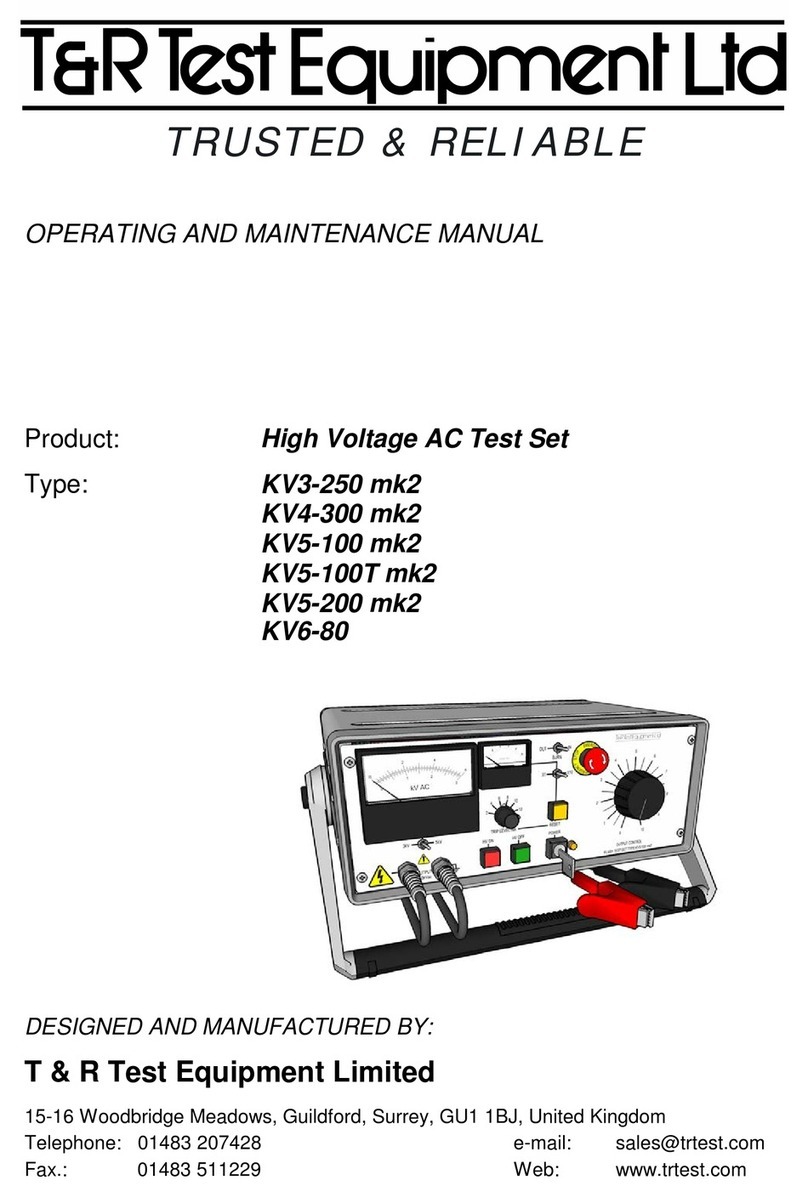
T&R 200A-3PH mk2 Operating instructions

1
OPERATING AND MAINTENANCE MANUAL
For Software Version 2.06 and later
Product:
3 Phase Secondary Injection Test Set
Type:
200A-3PH mk2
DESIGNED AND MANUFACTURED BY:
T & R Test Equipment Limited
15-16 Woodbridge Meadows, Guildford, Surrey, GU1 1BJ, United Kingdom
Fax.: 01483 511229 Web: www.trtest.com
TRUSTED & RELIABLE

2
GENERAL SAFETY STATEMENT
WARNING
The following safety precautions should be reviewed to avoid injury to the user and damage to the
product (and other products connected to it). To avoid potential hazards only use this product as
specified.
•Only suitably qualified personnel should use this equipment.
Servicing of this product should only be carried out by suitably qualified service personnel.
To Avoid Fire Hazards and Personal Injury
•Use the correct power supply lead. Only use a suitably rated and approved power supply lead for
the country of use.
•Ensure that systems that the unit is to be connected to are dead.
•Do not connect and disconnect leads whilst outputs are switched on. Breaking the output circuit
with current flowing may cause potentially fatal arcing.
•Ensure that the product is grounded. To avoid electric shock it is essential that the grounding
conductor is connected to the earth ground. An additional earth terminal is provided on the unit that
should be connected to a local earth. Ensure that the unit is properly grounded before making any
connections to inputs or outputs.
•Terminal ratings must be observed to prevent fire hazards and risk of injury to the operator.
Consult the product manual for ratings information before making connections to any terminal.
•It is ESSENTIAL to consult the product manual for rating information before making any connection
to a terminal or terminal group marked with a warning triangle.
•Only use fuses of a type and rating specified for this product.
•Do not operate the unit out of its case or with any covers or panels removed.
•Do not touch exposed connections and components when power is present.
•Do not operate the product if any damage is suspected. Refer the unit to qualified service
personnel to be checked.
•Do not operate the unit in wet or damp conditions
•Do not operate the unit in an explosive atmosphere
•The 200A-3PH mk2 system has a high output current (up to 200A), and therefore generates large
magnetic fields around the output leads. Care must be taken in siting the unit next to items sensitive
to magnetic fields (such as computer monitors and other sensitive equipment).
•Warnings from cardiac pacemaker manufacturers state that strong magnetic fields may affect
operation. Any high current unit such as the 200A-3PH mk2 should therefore not be operated by, or
in the vicinity of persons fitted with cardiac pacemakers or any other electronic or electrical medical
implants.
If any further queries occur regarding the usage and maintenance of the equipment
detailed in this manual, please refer these to the supplier of the equipment in the first case
or to the manufacturer, T & R Test Equipment Limited.

3
SAFETY TERMS AND SYMBOLS
The following safety symbols appear on the equipment:
CAUTION/WARNING –Refer to manual
Mains off
Mains on
The following safety symbols appear in this manual:
CAUTION
This action or procedure may be dangerous if not carried
out correctly, and may cause damage to the equipment or
connected equipment.
WARNING
This action or procedure may be cause injury or death to
the operator or other personnel if not carried out correctly
using applicable safety procedures.
CONVENTIONS USED IN THIS MANUAL
Text shown in CAPITALS refers directly to labels of controls on the front panel of the unit (e.g.
ADJUST refers to the auxiliary ac adjustment knob).

4

5
CONTENTS
1. DESCRIPTION OF EQUIPMENT 9
1.1 Front Panel Layout 10
1.2 Installation 11
1.2.1 Environment 11
1.2.2 Supply Requirements 11
1.2.3 Supply Voltage Connections 11
1.3 Functions 13
1.3.1 Main Current Outputs 13
1.3.2 Output Phase Relationships 14
1.3.3 Star-connected loads 15
1.3.4 Three phase loads with isolated elements 16
1.3.5 Current Metering 16
1.3.6 Auxiliary AC Voltage Output 17
1.3.7 Auxiliary Metering Input 17
1.3.8 Voltage Measurement 18
1.3.9 Current Measurement 18
1.3.10 Frequency Measurement 18
1.3.11 Phase Measurement 18
1.3.12 Timing System Specification 18
1.4 Displayed Values and Messages 24
1.4.1 Displayed Values 24
1.4.2 Warning Messages 24
1.5 Overload Protection 25
1.5.1 Storage of results 25
1.5.2 T&R link output contact 29
1.5.3 Phase Measurement 30

6
2OPERATION 32
2.1 Three Phase Over Current Relays 32
2.1.1 Connections 32
2.1.2 Test procedure 33
2.2 Timing of Auto-Reset/Reclosing Devices 33
2.2.1 Connections 33
2.2.2 Test procedure 34
2.3 Timing Circuit Breakers 34
2.3.1 Connections 35
2.3.2 Test procedure 35
2.3.3 Devices with short trip times 35
2.4 Directional relays (in conjunction with DVS3 mk2 voltage source) 36
2.4.1 Connections 37
2.4.2 Test procedure –restraint angle 37
2.4.3 Test procedure –overcurrent timing 38
3. MAINTENANCE 39
3.1 Regulator Brushes 39
3.2 Removal of the 200A-3PH mk2 from Case 39
4. STANDARD ACCESSORIES 40
4.1. Spares fuses supplied:- 40
4.2. Standard Accessories Supplied 40
4.3. Optional Accessories 40
5. OPTIONAL DELTA-STAR TRANSFORMER 41
5.1 Description 41
5.1.1 Front Panel Layout 42
5.1.2 Electrical Specification 42
5.2 Operation 44
5.2.1 Supply Voltage Connections 44
5.2.2 Connections between units 44

7
6. PERFORMANCE SPECIFICATION 46
6.1. Insulation Resistance at 1000V DC 46
6.2. Applied Voltage Test 46
6.3. Accuracy of Instrumentation and associated circuit components 46
6.3.1 Main Output Ammeter 46
6.3.2 Auxiliary Metering 46
6.3.3. Timing System 46
7. REVISION 47
8. DRAWINGS REQUIRED 48


9
1. DESCRIPTION OF EQUIPMENT
The 200A-3PH mk2 is a flexible 3 phase current injection system capable of supplying
currents of up to 200A ac per phase into a variety of loads. The unit is designed for testing
devices used for power system protection, but can be used wherever a 3 phase high current
AC source is required. The outputs may also be used to supply voltages of up to 5Vac.
An independently isolated output is provided for each phase, allowing a wide range of output
configurations to be selected.
A single phase isolated auxiliary AC output of 110Vac is also available.
The unit also has an auxiliary metering input with a fast capture time, allowing the
measurement of voltage, current, frequency, and phase.
The 200A-3PH mk2 requires a 3 phase 4 wire 400V ± 10% supply (50/60 Hz.)
The 200A-3PH mk2 is designed to be used on ‘dead’ systems (i.e. no externally supplied
voltages are present on the test object. Under no conditions connect the 200A-3PH mk2 to a
live system. Always check that the power to the device under test is off and the circuit is
isolated before making any connections.

10
1.1 Front Panel Layout
Ref
Item
Function
A
Main output –phase A
Phase A current output
B
Main output –phase B
Phase B current output
C
Main output –phase C
Phase C current output
D
Ammeter range switch
Selects ammeter range for main outputs
E
Mains input fuses
F
Mains input connector
G
Earth terminal
Connect to local ground for safety
H
I
Mains on/off switch
Store results control
Set comment, set clock, view stored
results, select auto results store mode
J
Auxiliary ac voltage output
Single phase 110V isolated output
K-M
Main output controls
Control main current output level
N
O
Main output on/off controls
Adjust Knob
Switches the main outputs on & off
Access results, and clock settings
P
Display
Shows current, time, aux input & status
Q
Auxiliary metering select
Selects auxiliary input function
R
USB sockets
Upper USB socket for connection of USB
memory key. Lower USB socket for
connection of keyboard
S
Timer mode switch
Selects timer mode
T
Timer contact sockets
Contact inputs for timer
U
V
W
Data storage Buttons
RS232 connector
T&R link connector
Select results to store
Serial data output for printer
Contact & phase lock outputs to DVS3
A
B
C
P
D
H
E
G
F
R
O
N
J
M
K
L
U
T
S
I
Q
W
V

11
1.2 Installation
1.2.1 Environment
The 200A-3PH mk2 is designed for use in indoor industrial and electrical substation
environments.
Maximum altitude: 2000m
Temperature: 0°C to 45°C operating
-20°C to 60°C storage
Relative humidity: 90% non-condensing
Protection rating: IP40 lid closed
IP20 in use
WARNING
In substation environments the earth terminal on the front panel of the unit
should be connected to a low impedance local earth.
WARNING
Ensure that the unit is connected to an appropriate supply by a suitably rated
connector.
1.2.2 Supply Requirements
The 200A-3PH mk2 requires a three phase 4 wire 50/60Hz supply of 400V ±10%. The
maximum power requirement of the unit is 1100VA per phase.
Other supply voltages may be catered for by using the optional 200A-DSU Delta-Star
converter. This allows the unit to operate from 3 wire supplies of 115V, 230V, 400V or 440V
(see section 5).
1.2.3 Supply Voltage Connections
The 200A-3PH mk2 is supplied with a five core supply cable with a CEE 400V 16A 3P+N+E 5
pin plug fitted. If this connector is not correct for the supply environment an adaptor will be
required.

12
If necessary the supply plug can be changed. Ensure that the plug is connected correctly. The
cores of the supply cable are marked to ensure correct phase rotation. The mains input lead
is marked as follows:
L1 Brown
L2 Black
L3 Grey
Neutral Blue
Earth Green and yellow
The unit requires a neutral connection (4 wire supply), and will not operate from a three wire
supply without the optional 200A-DSU delta-star converter.
It is essential that this unit is earthed.
Figure 1.1 Connections for mains input socket
1.2.3.1 Operation from a Single Phase Supply
If no three phase supply is available, it is possible to operate the 200A-3PH mk2 from a single
phase supply with reduced functionality. To connect the set to operate from a one phase
supply, connect L1, L2 and L3 to live, and N to neutral. When operating from a single phase
supply, all three outputs will be in phase.

13
1.3 Functions
1.3.1 Main Current Outputs
The main output on the 200A-3PH mk2 is used to inject current into test object to determine
operating (setting) levels and trip times. The outputs are taken from the ‘main output’ terminal
groups, and are switched on and off using the “OUTPUT ON” and “OUTPUT OFF”
pushbuttons, and the voltages of each phase (and hence current) are set using the “A”, “B”,
and “C” control knobs.
The main current output of the unit consists of three independent, isolated outputs derived
from the three phase mains supply. The phase difference between the outputs is therefore
fixed.
Each of the main outputs allows voltage output of 0-5 Vac. The ratings are shown in the table
below.
Voltage range
Current rating
Continuous
5min on/15 off
1min on/15 off
0-5V
50A
100A
200A
A true RMS ammeter with 20, 50, 100 and 200A ranges meters the output current. The meter
range is totally independent of the output tap, allowing any metering range to be used with
either of the output taps. It is always best to start by connecting the device under test (as
shown in Figure 1.2), and select the lowest current metering range that includes the desired
test current.
Figure 1.2 Example connection
Device under test

14
Each output is rated for a continuous current, and for higher intermittent currents. The
maximum ‘on’ time for intermittent currents is enforced by the unit, and the output will be
switched off if the rating is exceeded. The display will then show the following message until
the green ‘OFF’ button is pressed to clear the trip condition:
The outputs are rated for a maximum of four times the rated continuous current for 1 minute
on / 15 minutes off. The complete curve for intermittent current ratings is shown in figure 1.3.
Figure 1.3 200A-3PH mk2 maximum ‘on’ times
1.3.2 Output Phase Relationships
The phase relationship between the supply voltages and the output voltages are shown below.
The phase relationship between the output voltage and output current is determined by the
impedance of the load.
Figure 1.4 Supply and output phase relationships
% of continuous rated output current
Max ‘on’ time, seconds
200A-3PH
MK2 OUTPUT
C
A
B
COM C
COM B
COM A
Supply
400V STAR
(400V UNIT)
A
B
C
A
B
C
A
B
C
COM
C
B
COM
COM
COM
A
C
A
COM B
COM C
COM A
B

15
Note that any phase can be shifted by 180° by reversing the connections for that phase.
Equal currents are shown in the phasor diagrams overleaf, but unequal currents are equally
valid.
Delta output connections are not valid.
1.3.3 Star-connected loads
The configuration and interconnection of the outputs depends on the configuration of the load.
The configuration for injecting current into a three phase star-connected load is shown in
figure 1.5
Figure 1.5 Connections for star-connected load
A
C
B
STAR-CONNECTED LOAD

16
1.3.4 Three phase loads with isolated elements
It is also possible to inject current into three isolated loads, as occurs on some three phase
relays and MCBs. See figure 1.6.
Figure 1.6 Connections for load with isolated elements
1.3.5 Current Metering
The main output currents are metered by a true RMS reading digital memory ammeter. The
following ranges are available:
Range
Resolution
Accuracy
Trip current
20 A
0.01A
0.6% rdg 5d
21.0A
50 A
0.01A
0.6% rdg 5d
52.5A
100A
0.1A
0.6% rdg 5d
105.0A
200A
0.1A
0.6% rdg 5d
210A
THREE PHASE LOAD

17
The ammeter range is independent of the current output, and is therefore possible to meter
low currents very accurately from the lower voltage range, giving the best control of the output
current.
The unit has an electronic trip circuit that monitors the output current and switches the output
off if the trip value exceeds 105% of full scale of the metering range selected.
1.3.6 Auxiliary AC Voltage Output
The auxiliary AC voltage output is fixed at 110 Vac with a maximum output current of 300mA,
duty cycle 5 min on, 15 min off. The output is switched independently of the main output. The
voltage and current from this output may be metered using the auxiliary metering input.
1.3.7 Auxiliary Metering Input
The 200A-3PH mk2 has an auxiliary metering input which can be used to measure AC voltage
or current, frequency, and the phase between the main output and the auxiliary input. The unit
may measure either voltage or current derived quantities by selecting the appropriate input on
the front panel.
Two inputs are provided, one for voltages up to 300V and the other for currents up to 10A.
The input in use is automatically selected by the unit. Do not connect to both of the inputs
simultaneously.
WARNING
Voltage input Current input
Figure 1.8 Auxiliary inputs
Figure 1.7 Auxiliary AC output
Do not exceed the input ratings

18
1.3.7.1 Auxiliary input ranges
The following ranges are provided:
Range
Resolution
Accuracy
Frequency (V)
40.00-99.99Hz
0.01Hz
0.2% rdg 2d
Frequency (I)
40.00-99.99Hz
0.01Hz
0.2% rdg 2d
Phase (V)
180.0°
0.1°
3 degrees
Phase (I)
180.0°
0.1°
3 degrees
AC Voltage
0-300.0Vac rms
0.1V
0.7% rdg 5d
AC Current
0-10.000Aac rms
0.001A
0.7% rdg 5d
1.3.8 Voltage Measurement
To measure external voltages, connect the signal to the aux metering terminals marked ‘COM’
and ‘300V’. Ensure that the voltage to be measured is switched OFF when connecting the
leads.
The type of reading to be taken should then be selected using the aux metering rotary
selection switch. The frequency of the signal and phase relative to the main output current
may also be measured.
When measuring voltages, ensure that 300V ac is not exceeded on the 300V terminal.
1.3.9 Current Measurement
To measure current, connect to the ‘COM’ and ‘10A’ aux metering sockets. The aux metering
rotary switch selects the reading type.
1.3.10 Frequency Measurement
The frequency of the input signal may be measured for either a voltage or current input. To
measure frequency, the voltage or current must be greater than 1.6V or 0.03A respectively.
1.3.11 Phase Measurement
Switch to phase mode to measure the phase between the main current output selected by the
phase select switch and either the voltage or current input. In each case, the current or voltage
must be greater than 5% of the full scale of the range for the phase to be displayed and more
than 10% for the stated accuracy to be guaranteed.
1.3.12 Timing System Specification
The 200A-3PH mk2 is fitted with an integrated timing system that is linked to the main output
and two sets of contact inputs. The system is highly flexible, and allows for the timing of all
common protection devices and trips. The timer may also be used to time external events not
linked to the output of the set.

19
Timer information
Timer range
0-999.999s/9999.99s/99999.9s auto-ranging
Resolution
1ms/10ms/100ms
Accuracy
0.01% rdg 2d All modes except current operated
0.01% rdg 4d Current operated mode
Contact o/c voltage
24V
Contact s/c current
20mA
Contact indication
LED on –contact open
LED off –contact closed
Timer Modes
Timer Mode
Timer Start
Condition
Timer Stop
Condition
Automatic
output off
Example
application
Off
-
-
-
Set current
Internal Start
Main output on
C1 change
When timer
stops
IDMT relay
1 Contact using
Contact 1
C1 1st change
C1 2nd change
C1 1st change
(timer start)
Auto-reclose
relay
1 Contact using
Contact 2
C2 1st change
C2 2nd change
C2 2nd change
(timer stop)
Drop-off timing
2 Contacts
1st change C1
C1 change
C2 change
C2 change
(timer stop)
2 Contacts
1st change C2
C2 change
C1 change
Output cycles
on and off
Multiple auto re-
close timing
Current
Operated Phase
Select*
Current >20% of
range
Current <20% of
range
Current <20%
Timer stop
Miniature circuit
breakers
Pulse
Main output on
500ms
500ms
Set current for
thermal devices
* results obtained with test currents below 20% of range will give a lower accuracy than
specified.
The timer is automatically reset in every mode when the output is switched on. In each mode
that the timer is active, the output of the unit must be switched on to arm the timer.
Each contact channel has a contact input for volt-free contacts and a Vdc input for dc
voltages. The Vdc input may be used to trigger the timer from a dc voltage, and will trigger
from either the voltage switching from zero to 24-240Vdc or 24-240Vdc to zero. The voltage
must be connected with positive to the red “VDC” terminal and negative to the blue “COM”
terminal.

20
1.3.12.1 General Procedure for Timing Tests
To time the operation of any device a basic procedure needs to be followed to set the desired
test current and to carry out the timing test.
•Connect the device under test to the output of the unit and to the contact inputs as
required. For details of connection configurations, see the applications notes section.
•Set the timer to ‘off’ mode and the output control to zero. Switch on the output of the
unit, and increase the current or voltage to the desired level.
•Switch off the output of the unit and select the desired timer mode.
•Switch on the output of the unit. The timer will reset and then start when the start
condition is met. Any change to the timer switch setting will be ignored once the output
is switched on.
•The timer will stop when the stop condition is met.
1.3.12.2 Timer mode: OFF
In the ‘off’ mode, the timer has no effect on the operation of the set, and the timer does not
run. This mode is used to set the required current through the test object before a timing test.
1.3.12.3Timer mode: INTERNAL START
The internal start mode starts the timer when the main output is switched on, and stops the
timer on the first change of contact set 1. When the timer is stopped, the output of the unit is
automatically switched off.
1.3.12.4 Timer mode: 1 CONTACT
In single contact mode, the timer starts on the first change of state of CONTACT SET 1 after
the output is switched on, and stops on the second change on CONTACT SET 1. CONTACT
SET 1 or CONTACT SET 2 can be used in 1 contact mode. If C1 (CONTACT SET 1) is used,
the output is switched off when the timer is started, and if C2 (CONTACT SET 2) is used the
output is switched off when the timer stops.
Current
Contact set 1
Timer
Output ON
pressed and released
t
Current switches
off whencontact
changes
Figure 1.9 1 contact mode using CONTACT SET 1 (C1)
Table of contents
Other T&R Test Equipment manuals
T&R
T&R KV6-80 Operating instructions
T&R
T&R PCU2 mk5 Operating instructions
T&R
T&R CU-Ps Operating instructions
T&R
T&R KV30-40D mk3 Operating instructions

T&R
T&R Z-OVR Operating instructions

T&R
T&R PT30-10 mk2 Operating instructions
T&R
T&R KV30-40 Operating instructions
T&R
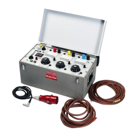
T&R 200A-3PH Operating instructions

T&R
T&R PT18-10 mk2 Operating instructions
T&R
T&R PT15-10s Operating instructions
Popular Test Equipment manuals by other brands
GW Instek
GW Instek GDS-3000 Series user manual
Badger Meter
Badger Meter Flo-tech PFM Series Installation & operation manual
Fluke
Fluke 6003A Operator's manual
Bante Instruments
Bante Instruments ECscan10 instruction manual

Smartek
Smartek IPC-3600 Series Quick start manual

M-system
M-system Mini-M M2CDS instruction manual
