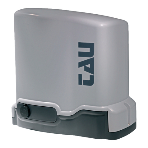
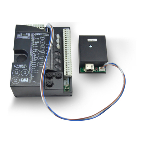
tau D770M Technical specifications

1
D770M
MANUALE D’USO E INSTALLAZIONE
USE AND INSTALLATION MANUAL
BENUTZUNGS- UND
INSTALLATIONSANLEITUNG
MANUEL D’EMPLOI ET INSTALLATION
MANUAL DE USO E INSTALACIÓN
D-MNL0D770M 23-11-2020 - Rev.01 Ver. Firmware 8.xx

2
SCHEMA CABLAGGIO D770M / D770M WIRING DIAGRAM / SCHALTPLAN DER D770M
O/C =Open/Close
Ped = Pedestrian
Cap = Capacitor
TX = Transmitter
RX = Receiver
E.L. = Electric lock
M = Motor
230 Vac-50 Hz
Power supply
Close
Common
Open
Close
Common
Open
Cap Cap
TX
1 2
RX
12345
Common
Sensitive edge
Internal photocell (N.C)
External photocell (N.C.)
Common
O/C
Ped
Stop
E.L.
12V 15W
2nd radio
channel
+
-
Gate open
warning light
max. 3W
Ext.
photoc.
Int.
photoc.
RX
12345
TX
1 2
11 12
D770M
F1
F2
123456789
29 30
1
3
2
4 5 6 7 8 9 10 11 12 13 14 15 16 17 18 19 2623 24 25 2827
20 21 22
29 30
TRA FR1 TCA
FR2
11
A/C
DL1
DL2 DL3 DL4 DL5 DL6
PED STP CF FI FE
10 12 13 14 15 16 17 18 25 26 27 28
22 23 24
19 20 21
P1 P2
DL8
DL7
J4
J3

3
SCHÉMA CÂBLAGE D770M / ESQUEMA DEL CABLEADO D770M / ESQUEMA ELÉCTRICO D770M
O/C =Open/Close
Ped = Pedestrian
Cap = Capacitor
TX = Transmitter
RX = Receiver
E.L. = Electric lock
M = Motor
230 Vac-50 Hz
Power supply
Close
Common
Open
Close
Common
Open
Cap Cap
TX
1 2
RX
12345
Common
Sensitive edge
Internal photocell (N.C)
External photocell (N.C.)
Common
O/C
Ped
Stop
E.L.
12V 15W
2nd radio
channel
+
-
Gate open
warning light
max. 3W
Ext.
photoc.
Int.
photoc.
RX
12345
TX
1 2
11 12
D770M
F1
F2
123456789
29 30
1
3
2
4 5 6 7 8 9 10 11 12 13 14 15 16 17 18 19 2623 24 25 2827
20 21 22
29 30
TRA FR1 TCA
FR2
11
A/C
DL1
DL2 DL3 DL4 DL5 DL6
PED STP CF FI FE
10 12 13 14 15 16 17 18 25 26 27 28
22 23 24
19 20 21
P1 P2
DL8
DL7
J4
J3

4
AVVERTENZE
Il presente manuale è destinato solamente al personale tecnico quali cato per l’installazione.
Nessuna informazione contenuta nel presente fascicolo può essere considerata d’interesse per l’utilizzatore
nale. Questo manuale è allegato alla centralina D770M, non deve pertanto essere utilizzato per prodotti
diversi!
Avvertenze importanti:
Togliere l’alimentazione di rete alla scheda prima di accedervi.
La centralina D770M è destinata al comando di un motoriduttore elettromeccanico per l’automazione di
cancelli, porte e portoni.
Ogni altro uso è improprio e, quindi, vietato dalle normative vigenti.
È nostro dovere ricordare che l’automazione che state per eseguire, è classi cata come “costruzione di una
macchina” e quindi ricade nel campo di applicazione della direttiva europea 2006/42/CE (Direttiva Macchine).
Questa, nei punti essenziali, prevede che:
- l’installazione deve essere eseguita solo da personale qualicato ed esperto;
- chi esegue l’installazione dovrà preventivamente eseguire “l’analisi dei rischi” della macchina;
- l’installazione dovrà essere fatta a “regola d’arte”, applicando cioè le norme;
- inne dovrà essere rilasciata al proprietario della macchina la”dichiarazione di conformità”.
Risulta chiaro quindi che l’installazione ed eventuali interventi di manutenzione devono essere eettuati solo
da personale professionalmente qualicato, in conformità a quanto previsto dalle leggi, norme o direttive
vigenti.
Nella progettazione delle proprie apparecchiture, TAU rispetta le normative applicabili al prodotto (vedere
la dichiarazione di conformità allegata); è fondamentale che anche l’installatore, nel realizzare gli impianti,
prosegua nel rispetto scrupoloso delle norme.
Personale non qualicato o non a conoscenza delle normative applicabili alla categoria dei “cancelli e porte
automatiche” deve assolutamente astenersi dall’eseguire installazioni ed impianti.
Chi non rispetta le normative è responsabile dei danni che l’impianto potrà causare!
Si consiglia di leggere attentamente tutte le istruzioni prima di procedere con l’installazione.
INSTALLAZIONE
Prima di procedere assicurarsi del buon funzionamento della parte meccanica. Vericare inoltre che il
gruppo motoriduttore sia stato installato correttamente seguendo le relative istruzioni. Eseguiti questi
controlli, assicurarsi che il motoriduttore non abbia un assorbimento durante il movimento superiore
a 3 A (per un corretto funzionamento del quadro di comando).
L’INSTALLAZIONE DELL’APPARECCHIATURA DEVE ESSERE EFFETTUATA “A REGOLA D’ARTE” DA PERSONALE
QUALIFICATO COME DISPOSTO DAL D.M. 37/08.
Nota: si ricorda l’obbligo di mettere a massa l’impianto nonché di rispettare le normative sulla sicurezza
in vigore in ciascun paese.
LA NON OSSERVANZA DELLE SOPRAELENCATE ISTRUZIONI PUÒ PREGIUDICARE IL BUON FUNZIONAMENTO
DELL’APPARECCHIATURA E CREARE PERICOLO PER LE PERSONE, PERTANTO LA “CASA COSTRUTTRICE” DECLINA
OGNI RESPONSABILITÀ PER EVENTUALI MAL FUNZIONAMENTI E DANNI DOVUTI ALLA LORO INOSSERVANZA.
1. SCHEDA DI COMANDO PER DUE MOTORI MONOFASE 230V AC
La scheda D770M è provvista di controllo elettronico delle sicurezze (fotocellule); tale verica viene
eettuata sulla fotocellula esterna solamente togliendo e ripristinando l’alimentazione, cosicchè il
microprocessore della centrale controlli che il relè abbia eettuato uno scambio senza problemi. Se
ciò non avviene, la centrale per sicurezza si blocca.
• LOGICA CON MICROPROCESSORE
• LEDS DI AUTODIAGNOSI
• PROTEZIONE INGRESSO LINEA CON FUSIBILE
• LIMITATORE DI COPPIA ELETTRONICO INCORPORATO
• VERIFICA ELETTRONICA DISPOSITIVI DI SICUREZZA
• FUNZIONE INGRESSO PEDONALE
• CIRCUITO INTEGRATO PER LAMPEGGIANTE A LED
ITALIANO

5
• RADIO RICEVITORE 433,92 MHz INTEGRATO A 2 CANALI (CH)
• FUNZIONE “RALLENTAMENTO” IN APERTURA E IN CHIUSURA
• DIAGNOSTICA DEL DIFETTO FUNZIONE VISUALIZZATO DA LED
• COMPATIBILITÁ CON L’APP TAUOPEN E TAUAPP
ATTENZIONE:
- Non utilizzare cavi unilari (a conduttore unico), es. quelli citofonici, al ne di evitare
interruzioni sulla linea e falsi contatti;
- Non riutilizzare vecchi cavi preesistenti.
- In caso di lunghi tratti di cavi ( > 20 m) per i comandi N.A. / N.C. (es: APRE/CHIUDE, STOP, PEDONALE,
ecc), al ne di evitare malfunzionamenti del cancello si renderà necessario disaccoppiare i vari
comandi mediante RELAYS oppure utilizzando il nostro dispositivo 750T-RELE.
2. COLLAUDO
A collegamento ultimato:
• I Leds verdi devono essere tutti accesi (corrispondono ciascuno ad un ingresso Normalmente Chiuso).
• Si spengono solo quando sono interessate le sicurezze alle quali sono associati.
• I Leds rossi devono essere tutti spenti (corrispondono ciascuno ad un ingresso Normalmente Aperto)
si accendono solo quando sono attivi i comandi ai quali sono associati.
• Il Led DL8 deve lampeggiare verde ogni 4 sec. (segnala lo stato logico della centrale, vedi sez. “Led di diagnosi”).
3. CARATTERISTICHE TECNICHE
Alimentazione scheda 230V AC - 50Hz
Potenza nominale max. motori 600 W ca.
Fusibile rapido protezione linea (F1 - 5x20) F 3,15 A
Tensione circuiti alimentazione motore 230V AC
Tensione alimentazione circuiti dispositivi ausiliari 24V AC
Tensione alimentazione lampeggiante a leds 12V DC
Fusibile rapido protezione linea 24 V ac (F2 - 5x20) F 500 mA
Tensioni alimentazioni circuiti logici 5V DC
Temperatura di funzionamento -20°C ÷ + 55 °C
Grado di protezione del contenitore* IP43
* Il contenitore della centrale nasce con grado di protezione IP65 ma viene dichiarato IP43 in
quanto si presume venga forato per essere ssato a parete e per permettere l’entrata dei cavi.
Non sapendo se i fori verranno provvisti di opportuni pressacavi o se saranno ermeticamente
sigillati si dichiara prudenzialmente un grado di protezione pari a IP43
4. COLLEGAMENTI ALLA MORSETTIERA
Legenda:
N.C. = Normalmente Chiuso N.A. = Normalmente Aperto
Morsetti Funzione Descrizione
1 - 2 - 3 ALIMENTAZIONE Ingresso ALIMENTAZIONE 230 Vac 50Hz (115 Vac 60 Hz).
1= FASE, 2= TERRA, 3= NEUTRO;
4 -5 - 6 MOTORE M1
Uscita alimentazione MOTORE M1 (motore che apre l’anta del cancello
con l’elettroserratura), 230 Vac, max 300 W;
4=CHIUDE, 5=COMUNE, 6=APRE.
Nota: collegare il condensatore fra i morsetti 4 e 6;
ITALIANO

6
7 - 8 - 9 MOTORE M2 Uscita alimentazione MOTORE M2, 230 Vac, max 300 W;
7=CHIUDE, 8=COMUNE, 9=APRE.
Nota: collegare il condensatore fra i morsetti 7 e 9;
10 - 11 APRE/CHIUDE Ingresso pulsante APRE/CHIUDE (contatto normalmente aperto); per le
modalità d’uso vedi le funzioni dei dip-switches nr 2 e 4. (10=COMUNE);
ATTENZIONE: con il dip 10 in ON l’ingresso commuta in APRE: l’automazione apre nchè
il pulsante viene mantenuto premuto. Al suo rilascio, l’automazione si ferma.
10 - 12 PEDONALE Ingresso pulsante PEDONALE (contatto normalmente aperto)
Comanda l’apertura e la chiusura totale del motore 1 ed è regolato nel
funzionamento dai dip-switches 2 e 4 (10 = COMUNE);
ATTENZIONE: con il dip 10 in ON l’ingresso commuta in CHIUDE: l’automazione chiude
nchè il pulsante viene mantenuto premuto. Al suo rilascio, l’automazione si ferma.
10 - 13 STOP
Ingresso pulsante STOP (contatto normalmente chiuso); il suo intervento
provoca l’arresto dell’automazione. Al successivo comando l’automazione
esegue una manovra opposta alla precedente (10=COMUNE). Ponticella-
re i morsetti se non utilizzati;
14 - 17 BORDO
SENSIBILE
ingresso BORDO SENSIBILE (contatto pulito N.C., dip 12 OFF) o BORDO SENSI-
BILE RESISTIVO 8,2 KΩ (dip 12 ON); Durante la fase di apertura provoca l’ ar-
resto temporaneo del cancello e una parziale richiusura dello stesso per
circa 20 cm liberando così l’eventuale ostacolo. Durante la fase di chiusu-
ra provoca l’arresto seguito dalla totale riapertura del cancello. In questo
caso, se programmata verrà inibita la chiusura automatica. Ponticellare i
morsetti se non utilizzati. (17= COMUNE - 14= BORDO SENSIBILE)
15 - 17 FOTOCELLULE
INTERNE
Ingresso FOTOCELLULE O DISPOSITIVI DI SICUREZZA INTERNI all’automa-
zione (contatto Normalmente chiuso); 17=COMUNE.
Il loro intervento, in fase di apertura, provoca l’arresto temporaneo
dell’automazione no a rimozione dell’ostacolo rilevato; in fase di chiu-
sura provoca l’arresto seguito dalla totale riapertura dell’automazione.
Ponticellare i morsetti se non utilizzati;
16 - 17 FOTOCELLULE
ESTERNE
Ingresso FOTOCELLULE O DISPOSITIVI DI SICUREZZA ESTERNI all’automazio-
ne (contatto Normalmente chiuso); 17=COMUNE.
Il loro intervento, ecace solo in fase di chiusura, provoca l’arresto seguito
dalla totale riapertura dell’automazione.
Ponticellare i morsetti se non utilizzati;
Nota: Il trasmettittore della fotocellula deve sempre essere alimentato
dai mors. 24 - 26, in quanto su questi si eettua la verica del sistema di
sicurezza (FOTOTEST), quindi senza questo collegamento la centralina
non accetterà nessun comando di apertura. Per eliminare la verica del
sistema di sicurezza porre il dip-switch n°6 in posizione OFF.
18 - 19 ELETTRO
SERRATURA Uscita alimentazione ELETTROSERRATURA
12 Vac max 15 W;
20 - 21 2° CH
RADIO
Uscita contatto 2° CANALE RADIO - RELAY K2 (contatto normalmente aper-
to); eventualmente la modalità di funzionamento è selezionabile mediante
TauApp;
Nota: per il collegamento di altri dispositivi al 2° canale radio, quali ac-
censione luci, comando pompe o carichi importanti, utilizzare un relè
ausiliario di potenza con portata adeguata ai dispositivi da collegare, al-
trimenti si potrebbero avere malfunzionamenti dovuti a disturbi indotti.
22 - 23 SPIA
CANCELLO
APERTO
Uscita SPIA CANCELLO APERTO - RELAY K3; 24 V ac, max 3W; la spia si
illumina con la stessa frequenza del lampeggiante per tutta la corsa in
apertura e in chiusura per rimanere accesa se il cancello è aperto, spenta
a completamento della fase di chiusura; eventualmente la modalità di fun-
zionamento è selezionabile mediante TauApp;
24 - 26 TX
FOTOCELLULE
Uscita alimentazione 24 Vac fotocellula trasmittente esterna per verica
dispositivi di sicurezza. (collegare solo la fotocellula TX esterna) max. nr. 2
trasmettitori fotocellule;
ITALIANO

7
25 - 26 AUX -
RX FOTOCELLULE Uscita 24Vac, 10W per l’alimentazione di fotocellule, ricevitori esterni, ecc.
27 - 28 LAMPEGGIANTE
Uscita LAMPEGGIANTE LEDS 12V dc, max 200mA (27 = negativo - 28 =
positivo)
Il segnale fornito è già opportunamente modulato per l’uso diretto.
La frequenza di lampeggio è doppia in fase di chiusura;
29 - 30 ANTENNA Ingresso ANTENNA (29=MASSA, 30=SEGNALE); L’ antenna normalmente è
integrata nel lampeggiante VLED.
5. REGOLAZIONI LOGICHE
TRIMMER
TRA Regolazione ritardo 2° motore: in chiusura da 0 a 30 sec. ca. (oltre al tempo che la scheda
calcola automaticamente durante la procedura di SETUP), in apertura da 0 a 6 sec. ca.
(oltre al tempo che la scheda calcola automaticamente durante la procedura di SETUP);
FR1
Regolazione coppia motore 1 (anta 1). Regolare il trimmer per una spinta del cancello
atta a garantire il funzionamento, facendo attenzione a non superare quella consentita
dalle norme in uso (EN 12453). Ruotando il trimmer in senso orario (+) si aumenta la
coppia motore, viceversa, ruotandolo in senso antiorario (-), diminuisce.
FR2
Regolazione coppia motore 2 (anta 2). Regolare il trimmer per una spinta del cancello
atta a garantire il funzionamento, facendo attenzione a non superare quella consentita
dalle norme in uso (EN 12453). Ruotando il trimmer in senso orario (+) si aumenta la
coppia motore, viceversa, ruotandolo in senso antiorario (-), diminuisce.
TCA Regolazione tempo di richiusura automatica da 2 a 120 secondi.
NOTA: Ruotando i TRIMMER in senso orario si aumentano le regolazioni, viceversa, ruo-
tandoli in senso antiorario, diminuiscono.
6. DIP-SWITCHES
1CHIUSURA
AUTOMATICA
On Ad apertura completata, la chiusura del cancello è automatica trascorso
un tempo impostato sul trimmer T.C.A.;
O La chiusura necessita di un comando manuale;
22 / 4 TEMPI
On Ad automazione funzionante, una sequenza di comandi di apertura/
chiusura induce il cancello ad una APERTURA-CHIUSURA-APERTURA-
CHIUSURA, etc. (vedi anche dip switch 3);
O Nelle stesse condizioni, la stessa sequenza di comandi di apertura/
chiusura induce il cancello ad una APERTURA-STOP-CHIUSURA-STOP-
APERTURA-STOP, etc. (funzione passo-passo);
3RICHIUDE DOPO
FOTOCELLULA
On In seguito all’intervento del contatto fotocellula (ingresso 16 - 17), l’au-
tomazione si chiude automaticamente dopo 5 secondi.
O Funzione disinserita.
4NO REVERSE On Il cancello in fase di apertura ignora i comandi di chiusura (NO REVERSE);
O Il cancello si comporta secondo la regolazione del dip-switch 2;
5PRE-LAMPEGGIO On La funzione prelampeggio è abilitata;
O La funzione prelampeggio è disabilitata;
6FOTOTEST
On La funzione “verica delle fotocellule” è inserita;
O La funzione “verica delle fotocellule” è disinserita. N.B.: da utilizzare
quando non si usano le fotocellule;
7COLPO D’ARIETE On La funzione “colpo d’ariete” è inserita. Permette lo sgancio dell’elettro-
serratura (da utilizzarsi solo se è presente l’elettroserratura);
O La funzione “colpo d’ariete” è disinserita;
ITALIANO

8
8* SELEZIONE
MOTORI
On È abilitato l’uso di un solo motore (M1).
O È abilitato l’uso di 2 motori.
9* RALLENTAMENTO On La funzione rallentamento è inserita (vedi “PROCEDURA DI IMPOSTA-
ZIONE DELLA CORSA (SETUP) ”);
O La funzione rallentamento è esclusa;
10** UOMO
PRESENTE
On Abilita la modalità UOMO PRESENTE: l’ingresso APRE/CHIUDE commuta
in APRE, l’ingresso PEDONALE commuta in CHIUDE;
O Funzionamento normale;
ATTENZIONE: con il dip 10 in ON l’ingresso APRE/CHIUDE (morsetti 10-11) commuta in
APRE, l’ingresso PEDONALE (morsetti 10-12) commuta in CHIUDE.
In modalità UOMO PRESENTE, non è necessario eseguire il setup corsa, ed i dip-switches
1, 2, 3, 4 e 9 sono inutilizzabili.
11 FUNZIONAMENTO
ELETTROSERRATURA
On Funzionamento dell’ elettroserratura per tutto il tempo di apertura e di
chiusura
O Funzionamento dell’ elettroserratura impulsivo: ad ogni apertura
l’elettroserratura funziona per un breve istante.
12 SELEZIONE
BORDO SENSIBILE
On BORDO SENSIBILE RESISTIVO (morsetto nr 14-17);
O BORDO SENSIBILE contatto pulito N.C. (morsetto nr 14-17).
Nota: lasciare in OFF se non utilizzato;
* E’ necessario eseguire il SETUP corsa se si modica il DIP.
** E’ necessario eseguire il SETUP corsa se si porta il DIP da ON a OFF
ATTENZIONE:
Per ogni coppia di morsetti facenti capo ad un contatto N.C. non utilizzato, bisogna eettuare un
cortocircuito per poter garantire il normale funzionamento della scheda.
L’impianto di massa a terra del portone deve essere conforme alle norme vigenti. La Casa Costruttrice
declina ogni responsabilità per i danni derivanti da eventuali inosservanze in materia.
7. PROCEDURA DI IMPOSTAZIONE DELLA CORSA (SETUP)
Collegare, all’uscita AP/CH della centrale, un selettore a chiave oppure un pulsante con contatto N.A.
quindi, per regolare la corsa delle ante, eseguire la seguente procedura:
- Se è già stata eseguita la procedura di memorizzazione del radiocomando, lo si può usare per
comandare la procedura;
CANCELLO 2 ANTE DIP 8 OFF (funzionamento 2 motori) - DIP 9 ON (rallentamento inserito):
1 Premere e mantenere premuto per almeno 5 secondi i pulsanti P1 e P2 per attivare la procedura;
2 Il led DL7 + DL8 cominciano a lampeggiare velocemente e le 2 ante si aprono;
Se l’automazione chiude anzichè aprire, fermare la corsa del cancello togliendo momen-
taneamente tensione. Invertire tra di loro le fasi del motore che chiude (morsetti 4-6 per
M1, morsetti 7-9 per M2) e riprendere la procedura dall’inizio dopo aver dato tensione.
3 Ad apertura completata, premere AP/CH (o il radiocomando), le 2 ante si arrestano;
4 Premere AP/CH (o il radiocomando), l’anta 2 si aziona in “corsa veloce” di chiusura;
5 Premere AP/CH nel punto desiderato per iniziare il rallentamento;
6 Ad anta completamente chiusa premere AP/CH (acquisizione corsa anta 2 completata);
7 Premere AP/CH, l’anta 1 si aziona in “corsa veloce” di chiusura;
8 Premere AP/CH nel punto desiderato per iniziare il rallentamento;
9 Ad anta completamente chiusa premere AP/CH (acquisizione corsa anta 1 completata);
10 Il led DL7 verde farà un lampeggio ogni 4 sec. (dati acquisiti e memorizzati correttamente);
CANCELLO 1 ANTA DIP 8 ON (funzionamento 1 motore) - DIP 9 ON (rallentamento
inserito):
1 Premere e mantenere premuto per almeno 5 secondi i pulsanti P1 e P2 per attivare la procedura;
2 Il led DL7 + DL8 cominciano a lampeggiare velocemente e l’ anta si apre;
ITALIANOITALIANO

9
Se l’automazione chiude anzichè aprire, fermare la corsa del cancello togliendo momen-
taneamente tensione. Invertire tra di loro le fasi del motore che chiude (morsetti 4-6 per
M1, morsetti 7-9 per M2) e riprendere la procedura dall’inizio dopo aver dato tensione.
3 Ad apertura completata, premere AP/CH (o il radiocomando), l’anta si arresta;
4 Premere 4 volte AP/CH, l’anta si aziona in “corsa veloce” di chiusura;
5 Premere AP/CH nel punto desiderato per iniziare il rallentamento;
6 Ad anta completamente chiusa premere AP/CH (acquisizione corsa anta completata);
7 Il led DL7 verde farà un lampeggio ogni 4 sec. (dati acquisiti e memorizzati correttamente);
CANCELLO 2 ANTE DIP 8 OFF (funzionamento 2 motori) - DIP 9 OFF (rallentamento
disabilitato):
1 Premere e mantenere premuto per almeno 5 secondi i pulsanti P1 e P2 per attivare la procedura;
2 Il led DL7 + DL8 cominciano a lampeggiare velocemente e le 2 ante si aprono;
Se l’automazione chiude anzichè aprire, fermare la corsa del cancello togliendo momen-
taneamente tensione. Invertire tra di loro le fasi del motore che chiude (morsetti 4-6 per
M1, morsetti 7-9 per M2) e riprendere la procedura dall’inizio dopo aver dato tensione.
3 Ad apertura completata, premere AP/CH (o il radiocomando), le 2 ante si arrestano;
4 Premere AP/CH (o il radiocomando), l’anta 2 si aziona in “corsa veloce” di chiusura;
5 Ad anta completamente chiusa premere AP/CH (acquisizione corsa anta 2 completata);
6 Premere AP/CH, l’anta 1 si aziona in “corsa veloce” di chiusura;
7 Ad anta completamente chiusa premere AP/CH (acquisizione corsa anta 1 completata);
8 Il led DL7 verde farà un lampeggio ogni 4 sec. (dati acquisiti e memorizzati correttamente);
CANCELLO 1 ANTA DIP 8 ON (funzionamento 1 motore) - DIP 9 OFF (rallentamento
disabilitato):
1 Premere e mantenere premuto per almeno 5 secondi i pulsanti P1 e P2 per attivare la procedura;
2 Il led DL7 + DL8 cominciano a lampeggiare velocemente e l’ anta si apre;
Se l’automazione chiude anzichè aprire, fermare la corsa del cancello togliendo momen-
taneamente tensione. Invertire tra di loro le fasi del motore che chiude (morsetti 4-6 per
M1, morsetti 7-9 per M2) e riprendere la procedura dall’inizio dopo aver dato tensione.
3 Ad apertura completata, premere AP/CH (o il radiocomando), l’anta si arresta;
4 Premere 3 volte AP/CH, l’anta si aziona in “corsa veloce” di chiusura;
5 Ad anta completamente chiusa premere AP/CH (acquisizione corsa anta completata);
6 Il led DL7 verde farà un lampeggio ogni 4 sec. (dati acquisiti e memorizzati correttamente);
Note:
- Durante la procedura di SETUP i dispositivi di sicurezza sono disattivati.
- Si consiglia di di impostare un tempo di qualche secondo superiore al necessario per garantire
la completa apertura/chiusura delle ante.
8. RADIO RICEVITORE 433,92 MHz INTEGRATO
Il radio ricevitore può apprendere no ad un max di 30 codici rolling code (S-2RP, S-4RP, K-SLIM-RP, T-4RP)
da impostare liberamente su due canali.
Il primo canale comanda direttamente la scheda di comando per l’apertura dell’automazione; il secondo
canale comanda un relè per un contatto pulito N.A. in uscita ai morsetti nr 20 e 21 (max 24V AC, 1 A)..
APPRENDIMENTO RADIOCOMANDI
P1 = 1° canale (APRE/CHIUDE) P2 = 2° canale
1_ Premere brevemente il tasto P1 se si desidera associare un radiocomando alla funzione APRE/
CHIUDE;
2_ Il led DL7 (verde) si accende sso per indicare la modalità di apprendimento dei codici (se non viene
immesso nessun codice entro 10 secondi, la scheda esce dalla modalità di programmazione);
3_ Premere il tasto del radiocomando che si desidera utilizzare;
4_ Il led DL7 (verde) si spegne per segnalare l’avvenuta memorizzazione e si riaccende subito in attesa
di altri radiocomandi (se ciò non accade, provare a ritrasmettere oppure attendere 5 secondi e
riprendere dal punto 1);
ITALIANOITALIANO

10
5_ Se si desidera memorizzare altri radiocomandi, premere il tasto da memorizzare sugli altri disposi-
tivi entro 5 sec. Passato questo lasso di tempo (il led verde DL7 si spegne) è necessario ripetere la
procedura dal punto 1 (no ad un massimo di 30 trasmettitori);
6_ Se si desidera eettuare la memorizzazione sul 2° canale, ripetere la procedura dal punto 1 utiliz-
zando il tasto P2 anzichè il tasto P1 (in questo caso il led rosso DL8 si accenderà);
Nel caso di raggiungimento del nr massimo di radiocomandi (nr 30), il led DL7 (verde) per
il CH1 ed il led DL8 (rosso) per il CH2 lampeggiano per circa 3 secondi senza però eseguire
la memorizzazione.
PROGRAMMAZIONE REMOTA TRAMITE T-4RP e K-SLIM-RP / S-2RP / S-4RP (V 4.X)
Con la versione di software V 4.X è possibile eseguire l’apprendimento remoto con i radiocomandi
T-4RP / K-SLIM-RP / S-2RP / S-4RP (V 4.X), ossia senza agire direttamente sui tasti di programmazione
della ricevente.
Sarà suciente disporre di un radiocomando già programmato nella ricevente per poter aprire la
procedura di programmazione remota dei nuovi radiocomandi. Seguire la procedura riportata sulle
istruzioni del radiocomando T-4RP / K-SLIM-RP / S-2RP / S-4RP (V 4.X).
CANCELLAZIONE RADIOCOMANDI
1_ Tenere premuto per 3 secondi ca. il tasto P1 al ne di cancellare tutti i radiocomandi ad esso asso-
ciati;
2_ Il led verde DL7 inizia a lampeggiare lentamente per indicare che la modalità di cancellazione è
attivata;
3_ tenere premuto nuovamente il tasto P1 per 3 secondi;
4_ Il led verde DL7 si spegne per 3 secondi ca. per poi riaccendersi sso ad indicare l’avvenuta cancel-
lazione;
5_ Riprendere la procedura dal punto 1 utilizzando il tasto P2 per cancellare tutti i radiocomandi ad
esso associati;
6_ Se si desidera uscire dalla modalità di cancellazione senza memorizzare un codice, premere breve-
mente il tasto P1 o il tasto P2.
MEMORIA CODICI
È possibile espandere la memoria dei codici da 30 * a 126, 254 o 1022, utilizzando le schede di memo-
ria come indicato (innestandole nel connettore J4, vedi schema cablaggio):
126 codici Art. 250SM126
254 codici Art. 250SM254
1022 codici Art. 250SM1022
* Le centrali, di serie, hanno una memoria di 30 codici. La scheda per la maggiorazione deve essere
ordinata a parte.
Per permettere lo spostamento dei codici già precedentemente memorizzati nella centrale (max. 30)
si renderà necessario installare una scheda di memoria facendo attenzione che la centrale sia in quel
momento spenta e che la scheda di memoria sia nuova di fabbrica e quindi completamente vuota.
Una volta inserita la nuova scheda di memoria alla riaccensione della centrale i codici si sposteranno
automaticamente nella stessa.
Lo spostamento dei codici da centrale a scheda di memoria non funziona nel caso in cui si uti-
lizzi una scheda di memoria sulla quale siano già stati memorizzati codici radiocomando e che
sia stata cancellata succesivamente.
Per inserire nuovi radiocomandi si ripeterà l’operazione descritta precedentemente.
ATTENZIONE: nel momento in cui si innesta/toglie una scheda di memoria, la centrale
deve essere spenta.
RESET DI FABBRICA:
- Con tensione spenta, premere e mantenere premuto il tasto P1.
ITALIANO

11
Alimentare la scheda (sempre tenendo premuto il tasto P1), il DL8 inizia a lampeggiare rosso.
Rilasciare il tasto P1, dopo 5 sec. i DL7-DL8 si spengono e si riaccendono lampeggiando verde/rosso
Eettuando un reset di fabbrica la memoria radio rimane invariata, pertanto i radio-
comandi esistenti rimangono memorizzati.
9. PREDISPOSIZIONE AL FUNZIONAMENTO CON LE APPLICAZIONI TAU
Per poter utilizzare le applicazioni TauApp e TauOpen si renderà necessario collegare all’ingresso J3
della centrale mediante il cavo in dotazione i rispettivi dispositivi T-WIFI e T-CONNECT.
Per attivare il funzionamento delle applicazioni vedere le rispettive istruzioni.
10. LED DI DIAGNOSI
DL1 - Rosso Led di segnalazione pulsante APRE/CHIUDE
DL2 - Rosso Led di segnalazione pulsante PEDONALE
DL3 - Verde Led di segnalazione pulsante STOP
DL4 - Verde Led di segnalazione BORDO SENSIBILE
DL5 - Verde Led di segnalazione FOTOCELLULE INTERNE
DL6 - Verde Led di segnalazione FOTOCELLULE ESTERNE
DL7 + DL8 Led di segnalazione programmazione RADIOCOMANDI, ERRORI e dello stato della
centrale di comando
LED: DL7 (verde) + DL8 (rosso)
I led DL7 e DL8 segnalano eventuali errori con una serie di lampeggi predeniti:
Legenda: led acceso sso; led lampeggiante; led spento;
/ Lampeggio alternato (Verde/
Rosso): Memorizzazione da eseguire;
/ Lampeggio veloce simultaneo
(Verde/Rosso): Memorizzazione in corso;
/ Nr. 8 lampeggi (Verde/Rosso): Errore dati in Eeprom;
Eseguire procedura di reset memoria Radio;
LED: DL7 (verde) + DL8 (rosso sempre spento)
1 Lampeggio ogni 4 sec. (Verde):Funzionamento regolare;
Oltre agli avvisi/errori della parte logica, il led DL7 indica anche lo stato della centrale durante la me-
morizzazione dei radiocomandi.
Sempre acceso (Verde): Canale CH1 in attesa di programmazione;
Lampeggio veloce (Verde): Memoria CH1 piena;
Lampeggio (Verde): Canale CH1 in attesa di cancellazione;
Spento: Canale CH1 in cancellazione
LED: DL8 (rosso) + DL7 (verde sempre spento)
Spento: Funzionamento regolare;
1 Lampeggio (Rosso):Errore fototest;
Disabilitare fototest (DIP-SWITCH 6 in OFF), verifare funziona-
mento fotocellule e il loro collegamento;
7 Lampeggi (Rosso):Intervento sicurezza bordo sensibile;
E’ necessario un’impulso di comando per aettuare la chiusura/
apertura;
ITALIANO

12
8 Lampeggi (Rosso):Errore memoria Eeprom esterna;
Sostituire il modulo di memoria esterna;
Oltre agli avvisi/errori della parte logica, il led DL8 indica anche lo stato della centrale durante la me-
morizzazione dei radiocomandi.
Sempre acceso (Rosso): Canale CH2 in attesa di programmazione;
Lampeggio veloce (Rosso): Memoria CH2 piena;
Lampeggio (Rosso): Canale CH2 in attena di cancellazione;
Spento: Canale CH2 in cancellazione
11. MALFUNZIONAMENTI: POSSIBILI CAUSE E RIMEDI
L’automazione non parte
a- Vericare con lo strumento la presenza dell’alimentazione 230Vac;
b- Vericare che i contatti N.C. della scheda siano eettivamente normalmente chiusi (4 led verdi
accesi DL3, DL4, DL5, DL6);
c- Impostare il dip 6 (fototest) su OFF;
d- Controllare con lo strumento che i fusibili siano integri.
Il radiocomando ha poca portata
a- Controllare che il collegamento della massa e del segnale dell’antenna non sia invertito;
b- Non eseguire giunzioni per allungare il cavo dell’antenna;
c- Non installare l’antenna in posizioni basse o in posizioni nascoste dalla muratura o dal pilastro;
d- Controllare lo stato delle pile del radiocomando.
Il cancello si apre al contrario
Invertire tra loro i collegamenti dei motori sulla morsettiera (morsetti 4 e 6 per il motore 1; morsetti
7 e 9 per il motore 2);
12. GARANZIA: CONDIZIONI GENERALI
La garanzia della TAU ha durata di 24 mesi dalla data di acquisto dei prodotti (fa fede il documento scale di
vendita, scontrino o fattura).
La garanzia comprende la riparazione con sostituzione gratuita (franco sede TAU: spese di imballo e di tra-
sporto sono a carico del cliente) delle parti che presentano difetti di lavorazione o vizi di materiale riconosciuti
dalla TAU.
In caso di intervento a domicilio, anche nel periodo coperto da garanzia, l’utente è tenuto a corrispondere il
“Diritto sso di chiamata” per spese di trasferimento a domicilio, più manodopera.
La garanzia decade nei seguenti casi:
• Qualora il guasto sia determinato da un impianto non eseguito secondo le istruzioni fornite dall’a-
zienda all’interno di ogni confezione.
• Qualora non siano stati impiegati tutti componenti originali TAU per l’installazione dell’automatismo.
• Qualora i danni siano causati da calamità naturali, manomissioni, sovraccarico di tensione, alimenta-
zione non corretta, riparazioni improprie, errata installazione, o altre cause non imputabili alla TAU.
• Qualora non siano state eettuate le manutenzioni periodiche da parte di un tecnico specializzato
secondo le istruzioni fornite dall’azienda all’interno di ogni confezione.
• Usura dei componenti.
La riparazione o la sostituzione dei pezzi durante il periodo di garanzia non comporta un prolungamento del
termine di scadenza della garanzia stessa.
In caso di utilizzo industriale o professionale oppure in caso di impiego simile, tale garanzia ha validità 12
mesi.
ITALIANO

13
DICHIARAZIONE DI INCORPORAZIONE DEL COSTRUTTORE
(ai sensi della Direttiva Europea 2006/42/CE AlI. II.B)
Fabbricante: TAU S.r.l.
Indirizzo: Via E. Fermi, 43 - 36066 Sandrigo (Vi) - ITALIA
Dichiara sotto la propria responsabilità che il prodotto: Centrale di comando
realizzato per il movimento automatico di: Cancelli a Battente
per uso in ambiente: Residenziale / Condominiale completo di: Radioricevente
Modello: D770M Tipo:D770M
Numero di serie: vedi etichetta argentata
Denominazione commerciale: Quadro di comando per due motori monofase 230V AC
È realizzato per essere incorporato su una chiusura (cancello a battente) o per essere assemblato con altri dispositivi
al ne di movimentare una tale chiusura per costituire una macchine ai sensi della Direttiva Macchine 2006/42/CE.
Dichiara inoltre che questo prodotto è conforme ai requisiti essenziali di sicurezza delle seguenti ulteriori direttive CEE:
- 2014/35/EU Direttiva Bassa Tensione - 2014/30/EU Direttiva Compatibilità Elettromagnetica
ed, ove richiesto, alla Direttiva:- 2014/53/EU Apparecchiature Radio e apparecchiature terminali di telecomunicazione
Dichiara inoltre che non è consentito mettere in servizio il macchinario no a che la macchina in cui sarà
incorporato o di cui diverrà componente sia stata identicata e ne sia stata dichiarata la conformità alle con-
dizioni della Direttiva 2006/42/CE.
Sono applicate le seguenti norme e speciche tecniche: EN 61000-6-2; EN 61000-6-3; EN 60335-1; ETSI EN 301
489-1 V1.9.2; ETSI EN 301 489-3 V1.6.1; EN 300 220-2 V2.4.1; EN 12453:2000; EN 12445:2000; EN 60335-2-103.
Si impegna a trasmettere, su richiesta adeguatamente motivata delle autorità nazionali, informazioni perti-
nenti sulle quasi-macchine.
Sandrigo, 10/06/2020 Il Rappresentante Legale
_________________________________________
Loris Virgilio Danieli
Nome e indirizzo della persona autorizzata a costituire la documentazione tecnica pertinente:
Loris Virgilio Danieli - via E. Fermi, 43 - 36066 Sandrigo (Vi) Italia
ITALIANO

14
WARNINGS
This manual has been especially written for use by quali ed tters. No information given in this manual
can be considered as being of interest to end users. This manual is enclosed with control unit D770M and
may therefore not be used for dierent products!
Important information:
Disconnect the panel from the power supply before opening it.
The D770M control unit has been designed to control an electromechanical gear motor for automating
gates and doors of all kinds.
Any other use is considered improper and is consequently forbidden by current laws.
Please note that the automation system you are going to install is classi ed as “machine construction”
and therefore is included in the application of European directive 2006/42/EC (Machinery Directive).
This directive includes the following prescriptions:
- Only trained and qualied personnel should install the equipment;
- the installer must rst make a “risk analysis” of the machine;
- the equipment must be installed in a correct and workmanlike manner in compliance with all the
standards concerned;
- after installation, the machine owner must be given the “declaration of conformity”.
This product may only be installed and serviced by qualied personnel in compliance with current, laws,
regulations and directives.
When designing its products, TAU observes all applicable standards (please see the attached declaration
of conformity) but it is of paramount importance that installers strictly observe the same standards when
installing the system.
Unqualied personnel or those who are unaware of the standards applicable to the “automatic gates
and doors” category may not install systems under any circumstances.
Whoever ignores such standards shall be held responsible for any damage caused by the system!
Do not install the unit before you have read all the instructions.
INSTALLATION
Before proceeding, make sure the mechanical components work correctly. Also check that the gear
motor assembly has been installed according to the instructions. Then make sure that the power
consumption of the gear motor is not greater than 3A (otherwise the control panel may not work
properly).
THE EQUIPMENT MUST BE INSTALLED “EXPERTLY” BY QUALIFIED PERSONNEL AS REQUIRED BY LAW.
Note: it is compulsory to earth the system and to observe the safety regulations that are in force
in each country.
IF THESE ABOVE INSTRUCTIONS ARE NOT FOLLOWED IT COULD PREJUDICE THE PROPER WORKING ORDER
OF THE EQUIPMENT AND CREATE HAZARDOUS SITUATIONS FOR PEOPLE. FOR THIS REASON THE “MANU-
FACTURER” DECLINES ALL RESPONSIBILITY FOR ANY MALFUNCTIONING AND DAMAGES THUS RESULTING.
1. CONTROL CARD FOR TWO SINGLE-PHASE MOTORS 230V AC
The D770M panel features an electronic photocell control system which switches the external photo-
cell transmitter on and o thereby causing the control unit microprocessor to check whether the relay
switches correctly. If this does not happen, the control unit is automatically blocked.
• MICROPROCESSOR-CONTROLLED LOGIC
• SELF-DIAGNOSIS LED’s
• LINE INPUT FUSE
• BUILT-IN TORQUE LIMITING DEVICE
• ELECTRONIC CONTROL OF SAFETY DEVICES
• PEDESTRIAN ENTRY FUNCTION
• BUILT-IN LED FLASHING LIGHT CIRCUIT
• 433.92 MHz 2 CHANNEL BUILT-IN RADIO RECEIVER (CH)
• “SLOW-DOWN” FUNCTION IN OPENING AND IN CLOSING PHASE
• DIAGNOSTICS OF MALFUNCTIONS SIGNALLED BY LED
ENGLISH

15
• COMPATIBILITY WITH OUR APPS: TAUOPEN AND TAUAPP
ATTENTION:
- do not use single cables (with one single wire), ex. telephone cables, in order to avoid break-
downs of the line and false contacts;
- do not re-use old pre-existing cables.
- In case of long sections of cables (> 20 m) for N.O./N.C. controls (e.g. OPEN / CLOSE, STOP,
PEDESTRIAN, etc.), in order to avoid gate malfunctions, it will be necessary to uncouple the
various controls using RELAYS or using our 750T-RELE device.
2. TESTING
When all connections have been made:
• All the green LED’s must be on (each corresponds to a Normally Closed input).
• They only turn o when the safeties they are associated with are active.
• All the red LED’s must be o (each corresponds to a Normally Open input) they only turn on when the com-
mands they are associated with are active.
• Led DL8 must ash green every 4 sec. (indicates the logic state of the control unit, see sect. “Diagnostics Led”)
3. TECHNICAL CHARACTERISTICS
Power input to board 230V AC - 50Hz
Max motors nominal power 600 W ca.
Primary input line rapid fuse (F1 - 5x20) F 3,15 A
Input voltage of motor circuits 230V AC
Input voltage of auxiliary circuits 24V AC
24Vac line rapid fuse (F2 - 5x20) F 500 mA
Logic circuit input voltage 5V DC
Working temperature -20°C ÷ + 55 °C
Box protected to IP43
* The control unit enclosure was created with IP65 protection rating but is declared IP43 as
it is expected to be drilled to be xed to the wall and to allow cable entry. Not knowing if the
holes will be provided with suitable cable glands or if they will be hermetically sealed, a de-
gree of protection equal to IP43 is prudently declared
4. TERMINAL BOARD CONNECTIONS
Key: N.C. = Normally Closed - N.O. = Normally Open
Terminals Function Description
1 - 2 - 3 POWER
SUPPLY POWER input 230 Vac, 50Hz (115 Vac 60 Hz);
1= PHASE, 2= EARTH, 3= NEUTRAL.
4 - 5 - 6 MOTOR M1 MOTOR M1 power output (opens the leaf tted with the electric
lock), 230 Vac, max. 300 W. 4=CLOSE, 5=COMMON, 6=OPEN.
Notice: connect the capacitor between terminals 4 and 6;
7 - 8 - 9 MOTOR M2 MOTOR M2 power output, 230 Vac, max. 300 W.
7=CLOSE, 8=COMMON., 9=OPEN.
Notice: connect the capacitor between terminals 7 and 9;
10 - 11 OPEN/CLOSE OPEN/CLOSE button input (contact normally open); for operating
information see dip-switches 2 and 4 functions. (COMMON=10);
WARNING: with dip 10 to ON the input switches OPEN: automation open as long as the
button is held down. On his release, the automation stops.
10 - 12 PEDESTRIAN PEDESTRIAN button contact input (contact normally open) – com-
mands total opening and closing of motor 1 – governed by dip-
switches 2 and 4. (COMMON=10);
ENGLISH

16
WARNING: with dip 10 to ON the input switches CLOSE: automation close as long as the
button is held down. On his release, the automation stops.
10 - 13 STOP STOP button input (normally closed contact); this stops the automatic
system. At the next command, the opposite operation to the previous
one is performed (COMMON=10). Bridge the connectors if not used;
14 - 17 SENSITIVE
EDGE
SENSITIVE EDGE input (potential free contact N.C., dip 12 OFF) or 8,2
KΩ RESISTIVE SENSITIVE EDGE (dip 12 ON); During the opening phase,
it temporarily stops the gate and makes it close again for about 20
cm, thus allowing to free the potential obstacle.
During the closing phase, it stops the gate and makes it totally
reopen. In this case, if programmed, the automatic closing will
be inhibited. Jumper terminals if not used. (17 = COMMON - 14 =
SENSITIVE EDGE)
15 - 17 INTERNAL
PHOTOCELLS
PHOTOCELL OR SAFETY DEVICE input INSIDE the automation (Nor-
mally Closed contact); COMMON=17.
When these devices trigger during the opening phase, they tem-
porarily stop the automation until the obstacle has been removed;
during the closing phase they stop the automation and then totally
open it again. Bridge the connectors if not used.
16 - 17 EXTERNAL
PHOTOCELLS
PHOTOCELL OR SAFETY DEVICE input OUTSIDE the automation (Nor-
mally Closed contact); COMMON=17.
Then these devices trigger during the closing phase, they stop the auto-
mation and then totally open it again. Bridge the connectors if not used.
Notice: Because the control of the safety system (FOTOTEST) is per-
formed on the photocell’s transmitter, this must always be pow-
ered by terminals 24 – 26, therefore if this connection is broken the
control unit will not accept any opening command. To eliminate
the safety system control, position dip-switch 6 to OFF.
18 - 19 ELECTRIC LOCK ELECTRIC LOCK power output 12 Vac max. 15 W;
20 - 21 2nd RADIO CH
2nd RADIO CHANNEL - RELAY K2 output (contact normally open); In
case the operating mode can be selected through TauApp;
Warning: to connect other devices to the 2nd Radio Channel
(area lighting, pumps, etc.), use an additional auxiliary relay.
22 - 23 GATE OPEN
WARNING LIGHT
GATE OPEN WARNING LIGHT - RELAY K3 output; 24 V ac, max 3W;
the light lights with the same frequency as that of the ashing light
for the entire opening and closing manoeuvre and remains on if the
gate is open and o when the gate has closed; In case the operating
mode can be selected through TauApp;
24 - 26 PHOTOCELL TX 24 Vac external transmitting photocell power supply output for
safety device control (connect the external TX photocell only) max.
of 2 photocell transmitters;
25 - 26 AUX - PHOTOCELL RX 24Vac output, 10W for the power supply of photocells, external receivers, etc.
27 - 28 FLASHING
LIGHT
LEDS FLASHING LIGHT output 12V dc, 200mA max.
(NEGATIVE=27 - POSITIVE=28)
The signal is already modulated for direct use. Flashing frequency is
double during closing;
29 - 30 AERIAL AERIAL input (EARTH=29, SIGNAL=30); The antenna is normally inte-
grated in the VLED ashing light
ENGLISH

17
5. LOGIC ADJUSTMENTS
TRIMMER
TRA
Second motor delay adjustment: during closing cycle from approx. 0 to 30 sec. (on top
of the time that the card calculates automatically during the SETUP procedure); during
opening from approx. 0 to 6 sec (on top of the time that the card calculates automati-
cally during the SETUP procedure).
FR1 Motor 1 torque adjustment (swing 1). The trimmer is set to provide sucient thrust to work
the gate without exceeding the limits established by current standards (EN 12453). Turning
the trimmer clockwise (+) increases the motor torque, turning it anticlockwise (-) reduces it.
FR2
Motor 2 torque adjustment (swing 2). The trimmer is set to provide sucient thrust to work
the gate without exceeding the limits established by current standards (EN 12453). Turning
the trimmer clockwise (+) increases the motor torque, turning it anticlockwise (-) reduces it.
TCA Automatic closing time adjustment from 2 to 120 seconds.
Notice: turn the TRIMMER clockwise to increase adjustments; turn it anticlockwise to
decrease.
6. DIP SWITCH
1AUTOMATIC
CLOSING
On After opening, the gate automatically closes when the delay set on the
T.C.A. trimmer expires;
O Automatic closing disabled;
22 / 4 STROKE
On With automatic closing enabled, a sequence of open/close commands
causes the gate to OPENCLOSE-OPEN-CLOSE etc (see also dip switch 3);
O In the same conditions, the same command sequence causes the gate
to OPEN-STOP-CLOSE-STOP-OPEN-STOP (step-by-step);
3CLOSES AGAIN
AFTER THE
PHOTOCELL
On After the photocell is activated (input 7 - 9), the automation closes auto-
matically after 5 seconds.
O function o.
4NO REVERSE On The gate ignores the close command while it is opening (NO REVERSE);
O The gate behaves according to the position of dip-switch n° 2;
5PRE-FLASHING On The pre-ashing function enabled;
O The pre-ashing function disabled;
6FOTOTEST
On The “photocell test” function is enabled;
O The “photocell test” function is disabled. N.B.: to be used when the pho-
tocells are not used;
7OPENING
RAM BLOW
On The “opening ram blow” function is on. This permits the release of the
electric lock (to be used only in the presence of an electric lock);
O The “opening ram blow” function is o;
8* MOTORS
SELECTION
On Enables just one motor (M1).
O Enables 2 motors.
9* DECELERATION On The deceleration function is on (see “PROGRAMMING INSTRUCTIONS”);
O The deceleration function is o;
10** MAN MODE On Enables the MAN mode: the OPEN / CLOSE input switches OPEN,
the PEDESTRIAN input switches CLOSE;
O Normal function
WARNING: with dip 10 ON the input OPEN / CLOSE (terminals 10-11) switches OPEN, the
PEDESTRIAN input (terminals 10-12) switches CLOSE.
In MAN mode, it is not necessary to run the race setup, and the dip-switches 1, 2, 3, 4
and 9 are not used.
ENGLISH

18
11 ELECTRIC LOCK
OPERATION
On Operation of the electric lock for the entire opening and closing time
O Impulsive operation of the electric lock: at each opening, the electric lock
works for a short moment.
12 SENSITIVE EDGE
SELECTION
On RESISTIVE SENSITIVE EDGE (terminal no. 15)
O RESISTIVE EDGE - potential free contact N.C. (terminal no. 15)
Note: if not used, keep the DIP in the OFF position.
* It is necessary to run the SETUP stroke if you modify the DIP.
** It is necessary to run the SETUP stroke if you turn the DIP from ON to OFF
IMPORTANT:
Each pair of terminals attached to an NC contact that is not in use must be short-circuited in order to
ensure the proper operation of the board.
The door’s earthing system must comply with current standards. The manufacturer will accept no li-
ability for any damage deriving from failure to comply with this requirement.
7. PROGRAMMING INSTRUCTIONS (SETUP)
If a transmitter has been previously programmed, it can be used to perform the following procedure.
Otherwise, connect a Key Switch or a NO Pushbutton to the AP/CH wire terminals on the controller.
DOUBLE SWING GATE - DIP 8 OFF (2 motors operation) - DIP 9 in ON (Soft-Stop function enabled):
1 Press and hold down for at least 5 seconds P1 and P2 buttons to activate the programming mode;
2 Leds DL7 + DL8 begin to ash quickly and the 2 wings open;
f the automation closes instead of opening, stop the gate travel by temporarily disconnecting
the voltage. Invert the phases of the motor that closes (terminals 4-6 for M1, terminals 7-9
for M2) and resume the procedure from the beginning after having given voltage.
3 Once opening is complete, press AP/CH button or the remote control: both leaves will stop;
4 Press AP/CH button or the remote control: the leaf #2 will close at standard speed;
5 Press AP/CH button or the remote control when the leaf should start to decelerate;
6 When the leaf is completely closed press AP/CH button or the remote control (leaf #2 programming completed);
7 Press AP/CH button or the remote control: the leaf #1 will close at standard speed;
8 Press AP/CH button or the remote control when the leaf should start to decelerate;
9 When the leaf is completely closed press AP/CH button or the remote control (leaf #1 programming completed);
10 The green led DL7 will ash every 4 sec. (programming completed and saved).
SINGLE SWING GATE - DIP 8 ON (1 motor operation) - DIP 9 in ON ( Soft-Stop function enabled):
1 Press and hold down for at least 5 seconds P1 and P2 buttons to activate the programming mode;
2 Leds DL7 + DL8 begin to ash quickly and the 2 wings open;
f the automation closes instead of opening, stop the gate travel by temporarily disconnecting
the voltage. Invert the phases of the motor that closes (terminals 4-6 for M1, terminals 7-9
for M2) and resume the procedure from the beginning after having given voltage.
3 Once opening is complete, press AP/CH button or the remote control: the leaf will stop;
4 Press 4 times AP/CH button or the remote control: the leaf will close at standard speed;
5 Press AP/CH button or the remote control when the leaf should start to decelerate;
6 When the leaf is completely closed press AP/CH button or the remote control (leaf programming completed);
7 The green led DL7 will ash every 4 sec. (programming completed and saved).
GATE 2 WINGS - DIP 8 OFF (2 motors operation) - DIP 9 in OFF (Soft-Stop function disabled):
1 Press and hold down for at least 5 seconds P1 and P2 buttons to activate the programming mode;
2 Leds DL7 + DL8 begin to ash quickly and the 2 wings open;
f the automation closes instead of opening, stop the gate travel by temporarily disconnecting
the voltage. Invert the phases of the motor that closes (terminals 4-6 for M1, terminals 7-9
for M2) and resume the procedure from the beginning after having given voltage.
3 Once opening is complete, press AP/CH button or the remote control: both leaves will stop;
4 Press AP/CH button or the remote control: the leaf #2 will close at standard speed;
5 When the leaf is completely closed press AP/CH button or the remote control (leaf #2 programming completed);
ENGLISH

19
6 Press AP/CH button or the remote control: the leaf #1 will close at standard speed;
7 When the leaf is completely closed press AP/CH button or the remote control (leaf #1 programming completed);
8 The green led DL7 will ash every 4 sec. (programming completed and saved).
SINGLE SWING GATE - DIP 8 ON (1 motor operation) - DIP 9 in OFF (Soft-Stop function disabled):
1 Press and hold down for at least 5 seconds P1 and P2 buttons to activate the programming mode;
2 Leds DL7 + DL8 begin to ash quickly and the 2 wings open;
f the automation closes instead of opening, stop the gate travel by temporarily disconnecting
the voltage. Invert the phases of the motor that closes (terminals 4-6 for M1, terminals 7-9
for M2) and resume the procedure from the beginning after having given voltage.
3 Once opening is complete, press AP/CH button or the remote control: the leaf will stop;
4 Press 3 times AP/CH button or the remote control: the leaf will close at standard speed;
5 When the leaf is completely closed press AP/CH button or the remote control (leaf programming completed);
6 The green led DL7 will ash every 4 sec. (programming completed and saved).
Notice:
- during the SETUP procedure the safety devices are disabled.
- set a working time slightly longer than necessary (a couple of seconds) to allow complete
opening/closing of the leaves.
8. 433.92 MHz BUILT-IN RADIO RECEIVER
The radio receiver can learn up to a maximum of 30 codes of rolling code (S2RP, S4RP, K-SLIM-RP, T-4RP)
to be set freely on 2 channels.
The rst channel directly commands the control board for opening the automatic device; the second
channel commands a relay for a N.O. no-voltage output contact (terminals 19 - 20, max. 24V AC, 1 A)
and the third channel controls directly the pedestrian opening from the controller.
LEARNING SYSTEM FOR RADIO CONTROL DEVICES
P1 = 1st channel (OPEN/CLOSE) P2 = 2nd channel
1_ Press button CH1 briey to associate a radio control device with the OPEN/CLOSE function;
2_ The (green) DL7 LED is ON to indicate the code learning mode has been activated (if no code is
entered within 10 seconds the board exits the programming function);
3_ Press the button of the relative radio control device;
4_ The (green) DL7 LED turns o to indicate saving is complete and then on again immediately waiting
for other radio control devices (if this is not the case, try to re-transmit or wait 5 seconds and restart
from point 1);
5_ To memorise codes to other radio control devices, press the key to be stored on other devices
within 5 sec. After this time (green DL7 LED turns o) must repeat the procedure from point 1 (up
to a maximum of 30 transmitters);
6_ If you wish to save on the 2nd channel, repeat the procedure from point 1 using the P2 key instead
of P1 (in this case the red DL8 LED will turn on);
f the maximum number of radio controls is reached (30), the led DL7 (green) for CH1
and the led DL8 (red) for CH2 ash for about 3 seconds without storing however.
REMOTE PROGRAMMING BY MEANS OF T-4RP / K-SLIM-RP / S-2RP / S-4RP (V 4.X)
With the new version of software V 4.X it is possible to carry out the remote self-learning of the new
version of transmitters T-4RP / K-SLIM-RP / S-2RP / S-4RP (V 4.X), that is without pressing the receiver’s
programming buttons.
It will be sucient to have an already programmed transmitter in the receiver in order to start the
procedure of remote programming of the new transmitters. Follow the procedure written on the
instructions of the transmitter T-4RP / K-SLIM-RP / S-2RP / S-4RP (V 4.X).
CANCELLING CODES FROM RADIO CONTROL DEVICES
1_ Keep button P1 pressed for 3 seconds in order to cancel all the associated radio control devices;
2_ (Green) DL7 LED ashes slowly to indicate that the cancellation mode has been activated;
3_ press button P1 again for 3 seconds;
4_ (Green) DL7 LED turns o for approx. 3 seconds and then remains steady to indicate that the code
has been cancelled;
ENGLISH

20
5_ repeat the procedure from point 1 using button P2 to cancel all the associated radio control devices;
6_ to exit the learning mode without memorising a code, press button P1 or P2 briey.
MEMORY CAPACITY
The code memory capacity* of the D770M can be expanded from 30 to 126, 254 or 1022 codes (transmit-
ters) by replacing the memory cards as follows
(plug them onto J4 connector, see wiring diagram)
:
126 codes Art. 250SM126
254 codes Art. 250SM254
1022 codes Art. 250SM1022
* Control units are supplied with a standard built-in 30-code memory. The memory card for enhancing the
code memory capacity must be ordered separately.
To allow the previously stored codes (max. 30) to be moved to the control unit, it is required to install
a memory card, making sure that the control unit is at that time o and that the memory card is brand
new and therefore completely empty.
When the control unit is restarted, the codes will automatically move to the memory card.
Moving the codes from the control unit to the memory card does not work if on the memory card used,
radio control codes have already been stored and the memory card has been subsequently erased.
To insert new radio controls, the operation described above shall be repeated.
WARNING: Control unit must be turned OFF to insert / remove a memory card.
HARD RESET (factory setting):
- With the power o, press and hold down the P1 button.
Power the board (always keeping the P1 button pressed), the DL8 starts ashing red.
Release the P1 button after 5 sec. the DL7-DL8 switch o and on again by ashing green/red
In case of Hard Reset the memory of the radio receiver will not be erased: all existing
transmitters remain programmed.
9. SET-UP FOR OPERATION WITH TAU APPS
In order to use the TauApp and TauOpen apps, it will be necessary to connect to input J3 of the control
unit using the supplied cable, the respective T-WIFI and T-CONNECT devices. To activate the operation
of the apps see the respective instructions.
10. DIAGNOSTICS LED
DL1 - Red OPEN/CLOSE button red LED signal
DL2 - Red PEDESTRIAN button red LED signal
DL3 - Green STOP button green LED signal
DL4 - Green SENSITIVE EDGE green LED signal
DL5 - Green INTERNAL PHOTOCELL green LED signal
DL6 - Green EXTERNAL PHOTOCELL green LED signal
DL7 + DL8 Led indicating the programming of REMOTE CONTROLS, ERRORS and the status of
the control unit
LED: DL7 (green) + DL8 (red)
Leds DL7 and DL8 displays any mistakes with a series of pre-set ashes:
Key: led always on; led ashing; led o;
/ Alternate ashing (green/red): Saving to be performed;
/ Simultaneous fast ashing
(green/red) Saving in progress;
/ No. 8 ashes (green/red): Eeprom data error;
ENGLISH
Other manuals for D770M
1
This manual suits for next models
1
Table of contents
Languages:
Other tau Gate Opener manuals
Popular Gate Opener manuals by other brands
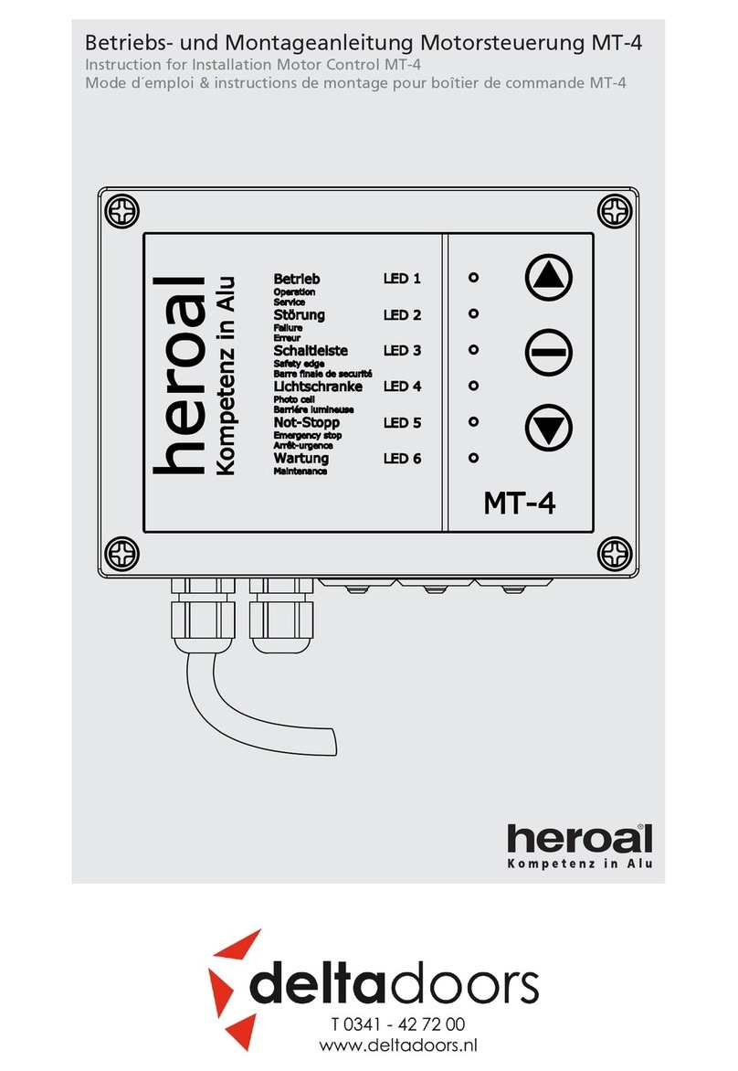
Deltadoors
Deltadoors heroal MT-4 Instructions for installation
SEA
SEA ORION BOX 24V manual
Shark
Shark 500KG Manual for installation and operation
Nice
Nice MhouseKit WU200S Instructions and warnings for installation and use
Nice
Nice SlideSmart CNX 15 Installation and programming manual
GTO
GTO SL-5000 installation instructions


