tau 900TWM User manual

1
TAU-WIRELESS
GUIDA ALL’INSTALLAZIONE
INSTALLATION GUIDE
INSTALLATIONSANLEITUNG
NOTICE D’INSTALLATION
GUÍA PARA LA INSTALACIÓN
TAU WIRELESS
Sistema wireless per gestione periferiche di sicurezza e controllo
Wireless system for management of safety and control peripherals
Wireless-system für die Verwaltung von Sicherheits- und Kontrollgeräten
Système sans l pour gestion de périphériques de sécurité et de contrôle
Sistema inalámbrico para la gestión de periféricas de seguridad y control
Via Enrico Fermi, 43 - 36066 Sandrigo (VI) Italia
Tel +39 0444 750190 - Fax +39 0444 750376
info@tauitalia.com - www.tauitalia.com
IT - Istruzioni originali
D-MNL0TWM-C 13-07-2011 - Rev.09

2
TAU-WIRELESS
ITALIANO
Questo manuale d’istruzioni contiene importanti informazioni riguardanti la sicurezza per l’installazione, è ne-
cessario leggere tutte le istruzioni prima di procedere all’installazione. Conservare con cura questo manuale
anche per utilizzi futuri.
Considerando i pericoli che si possono vericare durante l’installazione e l’uso di TAU-Wireless, per la massi-
ma sicurezza è necessario che l’installazione avvenga nel pieno rispetto di leggi, norme e regolamenti.
Secondo la più recente legislazione europea, l’automazione di una porta o cancello ricade in quanto
previsto dalla Direttiva 2006/42/CE (Direttiva Macchine) e nel particolare, alle norme: EN 13241-1 (nor-
ma armonizzata); EN 12445; EN 12453 ed EN 12635, che consentono di dichiarare la conformità alla
direttiva macchine.
Il presente manuale è destinato solamente al personale tecnico qualicato per l’installazione, nessuna altra
informazione contenuta nel presente fascicolo può essere considerata d’interesse per l’utilizzatore nale!
• L’uso di TAU-Wireless diverso da quanto previsto in queste istruzioni è vietato; usi impropri possono es-
sere causa pericoli o danni a persone e cose.
• Non eseguire modiche su nessuna parte se non previste nelle presenti istruzioni; operazioni di questo
tipo possono solo causare malfunzionamenti; TAU declina ogni responsabilità per danni derivati da pro-
dotti modicati.
• TAU-Wireless deve funzionare esclusivamente per interpolazione diretta TX-RX.
• Per i collegamenti elettrici utilizzare conduttori adeguati come riportato nel capitolo “collegamenti”.
• Accertarsi che l’alimentazione elettrica e gli altri parametri d’utilizzo corrispondano ai valori riportati nella
tabella “caratteristiche tecniche”.
• La realizzazione di dispositivi di sicurezza per porte e cancelli automatici è sottoposta alle seguenti norma-
tive:
• EN 12453 Porte e cancelli industriali, commerciali e da autorimessa. Sicurezza in uso di porte motorizzate
- Requisiti
• EN 12978 - Porte e cancelli industriali, commerciali e da garage. Dispositivi di sicurezza per porte e can-
celli motorizzate - Requisiti e metodi di prova.
L’installazione ed il collegamento di TAU-Wireless con lo scopo di realizzare un dispositivo di sicurezza, senza
soddisfare i requisiti di queste norme corrisponde a negligenza e deliberato abuso!
Avvertenze particolari sull’idoneità all’uso di questo prodotto in relazione alla Direttiva “Compatibilità Elettro-
magnetica“ 2004/108/CE:
questo prodotto è stato sottoposto alle prove relative alla compatibilità elettromagnetica nelle situazioni d’uso
più critiche, nelle congurazioni previste in questo manuale di istruzioni ed in abbinamento con gli articoli
presenti nel catalogo prodotti di TAU s.r.l. Potrebbe non essere garantita la compatibilità elettromagnetica se il
prodotto è usato in congurazioni diverse o con altri prodotti non previsti; è vietato l’uso del prodotto in queste
situazioni nché chi esegue l’installazione non abbia vericato la rispondenza ai requisiti previsti dalla direttiva.
DESCRIZIONE E FUNZIONAMENTO
TAU Wireless è un dispositivo che consente di risolvere il problema dei collegamenti elettrici di bordi sensi-
bili posti su ante in movimento e non. Il sistema è composto da :
1_ Base (TWM) che gestisce i sensori (via radio) ed i comandi da e per il quadro del cancello (via cavo).
2_ Sensore (TWC) che invia il segnale del bordo sensibile (ad esso collegato) con contatto NC o resistivo,
da utilizzare come bordo sensibile sso e/o bordo sensibile mobile.
Tutti i dispositivi, base e sensori, sono dotati di un transceiver in grado di ricevere e trasmettere dati sulla
frequenza standard di 868 MHz.
TAU Wireless consente la possibilità di utilizzo come parte di un dipositivo di sicurezza sensibile alla pres-
sione (PSPE), tramite la verica dello stato del bordo sensibile: il bordo sensibile, di tipo a resistenza co-
stante 8,2kohm o contatto NC (normalmente chiuso), viene vericato continuamente dal sensore TWC e lo
stato di attivazione o meno viene inviato alla base TWM. Quest'ultima interpreta l’informazione ricevuta e la
comunica alla centrale elettronica dell'automazione.
Il sistema TAU Wireless è compatibile con tutte le centrali TAU dotate dell'uscita SPIA CANCELLO APER-
TO con lampeggio proporzionale: D703M - D704M - D705M - D747M - D750M - D760M - K120M - K122M
- K123M - K125M - K570M - K580M.
Nota: utilizzare il sistema TAU-Wireless solo ed esclusivamente con centrali di comando TAU.
DICHIARAZIONE CE DI CONFORMITÀ
Con la presente dichiariamo che il nostro prodotto:
Sistema wireless (900TWC - 900TWM)
è conforme alle seguenti disposizioni pertinenti:
1999/5/CE Apparecchiature Radio e apparecchiature terminali di telecomunicazione
EN 954-1:1996 Categoria 2 Il Rappresentante Legale
_________________________________________
Bruno Danieli

3
TAU-WIRELESS
Il sistema funziona secondo queste fasi principali:
1_ Con cancello non attivo la base TWM e i sensori TWC sono in standby.
2_ La base TWM viene attivata dalla centrale mediante l'uscita "SPIA CANCELLO APERTO".
Nota: con la base TWM cablata, non collegare nessun altro dispositivo all'uscita SPIA CANCEL-
LO APERTO" della centrale.
3_ All'impulso di apertura, la base TWM trasmette ai sensori TWC un comando generale di attivazione, e li
mette in ricezione permanente.
4_ Ad automazione funzionante, la base TWM invia un segnale a tutti i sensori TWC programmati, che
sequenzialmente trasmettono ad essa lo stato del bordo sensibile e della batteria. Il processo avviene
continuamente.
5_ Se uno o più sensori TWC sono in allarme questo stato viene trasmesso alla base TWM. Quest'ultima
aprirà il contatto relativo al dispositivo allarmato, determinando lo stop dell’automatismo.
6_ La base TWM rimane attiva per alcuni secondi dopo l'arresto dell'automatismo, vericato con l'ingresso
SPIA CANCELLO APERTO. Allo scadere del tempo il sistema si rimette in standby (punto 1). La fase
attiva viene indicata dal led rosso DL9 che rimane acceso.
7_ La presenza di uno o più sensori TWC con batteria scarica viene segnalata con il lampeggiare del led
verde relativo:
Lampeggio normale: batteria scarica.
Lampeggio veloce: mancata comunicazione radio (batteria esausta, probabili disturbi sulla frequenza
radio, possibile guasto del sensore relativo).
CARATTERISTICHE TECNICHE
Alimentazione scheda TWM 12/24 Vdc/Vac
Corrente assorbita scheda TWM 70 mA
Alimentazione sensore TWC 2 pile stilo AA 1,5V
Portata massima 20 m
Tensioni alimentazioni circuiti logici 5 Vdc
Grado di protezione contenitore TWM IP 44
Grado di protezione contenitore TWC IP 43
Temperatura di funzionamento -20 °C ÷ +70 °C
LED DI DIAGNOSI
DL1 led verde di segnalazione BORDO SENSIBILE FISSO
DL2 led verde di segnalazione BORDO SENSIBILE MOBILE
DL3 led verde di segnalazione TX FOTO 1
DL4 led verde di segnalazione TX FOTO 2
DL5 led verde di segnalazione RX FOTO 1
DL6 led verde di segnalazione RX FOTO 2
DL7 led verde di segnalazione START - STOP
DL8 led verde di segnalazione LAMPEGGIANTE
DL9 led rosso di segnalazione FUNZIONE
INSTALLAZIONE
Tutte le operazioni d’installazione vanno eseguite in assenza di tensione all’impianto; nel caso sia
presente la batteria tampone, è necessario scollegarla.
Veriche preliminari
Vericare attentamente che i parametri di utilizzo siano concordi con i dati riportati nel capitolo “Caratteri-
stiche tecniche”. In caso di dubbio non utilizzare il prodotto e richiedere chiarimenti al servizio di assistenza
tecnica di TAU.
Per il ssaggio del bordo sensibile, attenersi alle istruzioni allegate al prodotto.
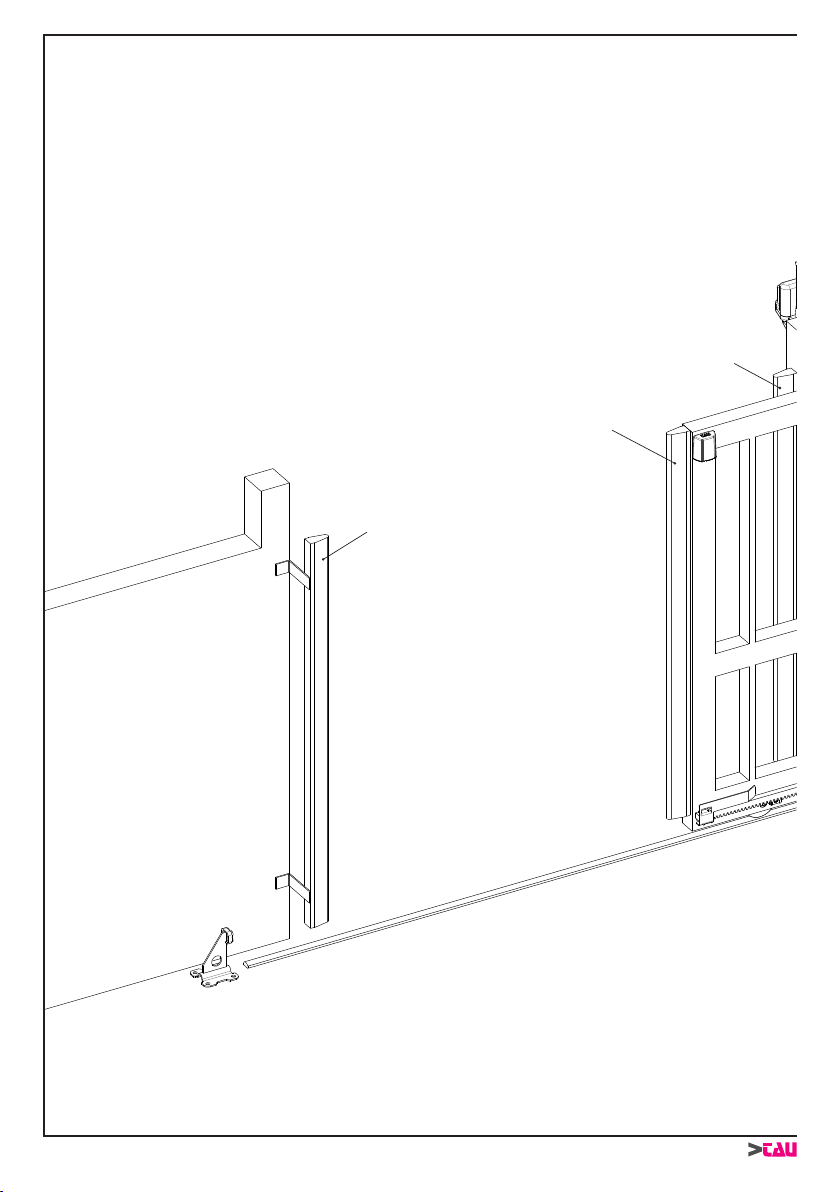
Per la corretta installazione, procedere come segue:
1_ Collocare il sensore TWC in prossimità del bordo sensibile ssando prima la staffetta di supporto (1
g.1) con due viti (2 g.1) adeguate alla struttura del cancello. Inserire la scheda TWC (3 g.1) negli
appositi supporti della base
2_ Collegare il sensore TWC al bordo sensibile facendo passare i cavi all'interno del cancello (g.2). Si
consiglia di utilizzare cavi di sez. 0,5 mm².
ITALIANO

4
TAU-WIRELESS
3_ Individuare l’area più idonea alla collocazione della base TWM (si consiglia di utilizzare l’apposito con-
tenitore ed ubicarla esternamente in prossimità della centrale elettronica, se quest’ ultima non è incor-
porata al motoriduttore).
N.B. Se il carter del motore è in metallo (es. serie BIG) è necessario collocare la base TWM ester-
namente al motore con l’apposito contenitore. Anche nei casi in cui il carter non è metallico è
poco opportuno posizionare la base TWM in prossimità del vano motore ed in generale vicino a
masse metalliche per non compromettere l’efcienza di ricetrasmissione.
4_ Chiudere il contenitore scheda con il relativo coperchio (4 g.1).
5_ Esistono 2 diverse congurazioni di installazione: come sicurezza in chiusura (1-2 g.3) e/o in apertura
(3-4 g.3). Nelle situazioni 1 e 2, il relè di uscita della scheda TWM deve essere collegato all'ingresso
fotocellule del quadro che comanda l'automazione (sia per bordo sensibile mobile che sso), e in serie
alla/e fotocellule stesse (vedi schema di g.4) in modo che i bordi sensibili siano attivi in fase di chiusura.
Nelle situazioni 3 e 4, il relè di uscita della scheda TWM deve essere collegato all'ingresso CF (costa
ssa) del quadro che comanda l'automazione (sia per bordo sensibile mobile che sso) in modo che i
bordi sensibili siano attivi in fase di apertura, o in serie ad altri bordi sensibili ssi (vedi schema di g.4).
6_ Osservare che è possibile il montaggio di un solo TWC su bordo sensibile attivo in fase di apertura ed
uno solo su bordo sensibile attivo in fase di chiusura (sia per bordi sensibili ssi che mobili). Prendendo
ad esmpio la g. 3, non è possibile installare su un'unica base TWM i bordi sensibili 1 e 2 oppure i bordi
sensibili 3 e 4. Al contrario, si possono installare su un'unica base TWM i bordi sensibili 2 e 3, oppure 2
e 4, etc.
N.B. Abilitare sempre la funzione prelampeggio sulla scheda di comando dell’automazione per
avere i sensori attivi non appena il cancello inizia a muoversi.
COLLEGAMENTI (g.4)
COLLEGAMENTI ALLA MORSETTIERA (TWM)
1 - 2 Ingresso alimentazione 12/24 Vdc/Vac.
3 Non collegato.
4 Ingresso SPIA CANCELLO APERTO.
5 Comune dei contatti (da collegare SEMPRE direttamente alla centrale di comando).
6 Non collegato
7 Non collegato
8 Uscita contatto BORDO SENSIBILE -costa ssa (5 = COMUNE - 8 = BORDO SENSIBILE),
contatto normalmente chiuso NC (corrisponde al led DL1).
9 Uscita BORDO SENSIBILE - costa mobile (5 = COMUNE - 9 = BORDO SENSIBILE), contatto
normalmente chiuso NC (corrisponde al led DL2).
J2 Selezione alimentazione: Ponticello chiuso per 12 Vac/dc, non ponticellare per 24 Vac/dc.
J3 Selezione del collegamento all'ingresso bordo sensibile della centrale. J3 inserito se la centrale
è predisposta all'ingresso di tipo ON/OFF; non ponticellare J3 se l'ingresso è resistivo a 8,2
KΩ.
J4 Ponticellare se alimentato con tensione continua; non ponticellare se alimentato con tensione
alternata (vedi tabella 1).
COLLEGAMENTI ALLA MORSETTIERA (TWC)
1 - 2 Ingresso contatto NC BORDO SENSIBILE (o BORDO SENSIBILE RESISTIVO) - costa ssa o
mobile.
DIP-SWITCH
Dip Funzione
1-2-3 Frequenza di trasmissione del sistema
Nota: variando la congurazione dei dip-switches si varia la frequenza di trasmissione
tra base e relativi sensori (per ovviare alle eventuali interferenze tra diverse installazioni).
Ogni modica di frequenza sui dip 1-2-3 impone la ripetizione della “PROCEDURA DI
CANCELLAZIONE” e “PROCEDURA DI PROGRAMMAZIONE”.
N.B: nel caso in cui ci siano due o più impianti che utilizzano il sistema TAU-wireless,
sarà necessario impostare una frequenza di funzionamento diversa per ognuno (dip 1-2-
3), onde evitare che si disturbino tra loro.
4OFF: bordo sensibile non resistivo
ON: bordo sensibile resistivo
Nota: il dip serve per congurare il sensore TWC al tipo di bordo sensibile utlizzato (resi-
stivo o non resistivo). È possibile utilizzare contemporaneamente sia un bordo sensibile
resistivo che uno non resistivo, previo un corretto settaggio del dip-switch prima di ogni
singola procedura di programmazione.
IMPORTANTE: settare il dip-switch prima di eseguire ogni singola procedura di program-
mazione.
ITALIANO

5
TAU-WIRELESS
PROGRAMMAZIONE
Eseguire una procedura di cancellazione prima di iniziare la programmazione (vedi par. successivo). Solo
dopo eseguire la fase di programmazione.
PROCEDURA DI CANCELLAZIONE
Sensori: Premere il pulsante di cancellazione per almeno 5 secondi (vedi gg. 4-5).
Base: premere il pulsante di programmazione no all’accensione, prima lampeggiante e poi ssa, ed
il successivo spegnimento del led rosso (DL9). Rilasciare il tasto quando il led si spegne.
PROCEDURA DI PROGRAMMAZIONE
La programmazione si attua dopo avere cablato la base alla scheda dell’automatismo e il/i sensore/i alla/e
costa/e.
1. Inserire le batterie nel sensore TWC rispettando le polarità.
2. Impostare un codice sulla bancata dei dip-switches presente sulla scheda base TWM. Questo assicura
che il sistema possa funzionare anche in prossimità di altri sistemi wireless che, ovviamente, devono
avere codici diversi. Utilizzare i dip 1-2-3 per l’impostazione ottenendo no a 8 combinazioni. Il dip 4
viene utilizzato per selezionare il tipo di bordo sensibile, Dip 4 OFF bordo sensibile NON resistivo, DIP
4 ON per bordo sensibile resistivo.
Nota: variando la congurazione dei dip-switches si varia la frequenza di trasmissione tra base
e relativi sensori (per ovviare alle eventuali interferenze tra diverse installazioni). Ogni modica
di frequenza sui dip 1-2-3 impone la ripetizione della “PROCEDURA DI CANCELLAZIONE” e
“PROCEDURA DI PROGRAMMAZIONE”.
3. Alimentare l’automatismo. Tutti i led dovranno essere spenti. Se uno o più led verdi dovessero essere
accesi, passare alla sezione “PROCEDURA DI CANCELLAZIONE”.
4. Premere per circa 3 secondi il tasto di programmazione della base TWM no a che il led “costa ssa”
(DL1) lampeggia. Passare al punto 6 se non si desidera installare questo sensore.
5. Premere il pulsante di programmazione sul sensore TWC a cui si vuole assegnare la funzione di costa
ssa (Bordo sensibile attivo in apertura). Il led “costa ssa” (DL1), rimarrà acceso sso appena eseguita
la programmazione del sensore. Rilasciare il tasto sul sensore.
6. Premere una volta il tasto di programmazione sulla base. Ora lampeggia il led relativo alla “costa mobi-
le” (DL2).
7. Premere il pulsante di programmazione sul sensore TWC a cui si vuole assegnare la funzione di costa
mobile (Bordo sensibile attivo in chiusura). Il led “costa mobile” (DL2), rimarrà acceso sso appena
eseguita la programmazione del sensore. Rilasciare il tasto sul sensore.
8. Premere per 3 secondi il pulsante di programmazione sulla base. I led dei sensori programmati si spen-
gono per circa 1 secondo. Appena si riaccendono, rilasciare il pulsante. La programmazione è conclusa.
NB: saltare i passi 6 e 7 nel caso di programmazione di un solo bordo sensibile utilizzato come costa
ssa (Bordo sensibile attivo in apertura).
TABELLA 1: CABLAGGIO DELLA BASE TWM ALLE CENTRALI TAU
TWM (morsetto n°) 1 2 3 4 5 6 7 8 9 Ponticellare
J2 J4
D703M (morsetto n°) 30 29 N.U. 25 16 N.U. N.U. 17 18 no no
D704M / D705M (morsetto n°) 26 25 N.U. 27 17 N.U. N.U. 18 16 no no
D747M (morsetto n°) 1 2 N.U. 7 18 N.U. N.U.
16/19
15 sì sì
D750M (morsetto n°) 27 26 N.U. 23 18 N.U. N.U. 15 17 no no
D760M (morsetto n°) 27 26 N.U. 23 18 N.U. N.U. 15 17 no no
K120M (morsetto n°) 8 9 N.U. 14 3 N.U. N.U. 1 2 sì sì
K122M (morsetto n°) 1 2 N.U. 7 12 N.U. N.U. 9 10 sì sì
K123M (morsetto n°) 3 4 N.U. 9 14 N.U. N.U. 11 12 sì sì
K125M (morsetto n°) 8 9 N.U. 14 3 N.U. N.U. 1 2 sì sì
K570M (morsetto n°) 24 23 N.U. 20 13 N.U. N.U. 14 15 no no
K580M (morsetto n°) 14 13 N.U. 17 10 N.U. N.U. 11 12 no no
N.U. = Non Utilizzato
ITALIANO

6
TAU-WIRELESS
ENGLISH
This instruction manual contains important information regarding installation safety; therefore read all in-
structions carefully before proceeding with installation. Keep this manual in a safe place for future use.
To ensure the maximum safety, in consideration of the hazards that may arise during installation and use
of TAU-Wireless, the installation procedures must be performed in full compliance with the law, current
standards and regulations.
According to the most recent European legislation, the automation of a door or gate is subject to
the specications of the Machinery directive 2006/42/EC and more specically to the standards:
EN 13241-1 (harmonised standard); EN 12445; EN 12453 and EN 12635, which enable declaration of
conformity with the Machinery Directive.
This manual is intended exclusively for technical personnel qualied for installation; no other information in
this document may be considered of interest to the nal user.
• Use of TAU-Wireless other than as specied in this instruction manual is strictly prohibited; improper use
constitutes a risk of physical injury or damage to objects.
• Do not perform any modications to parts unless envisaged in these instructions; operations of this kind
will only lead to malfunctions; TAU declines all liability for damage caused by modied products.
• TAU-Wireless must operate exclusively for direct TX-RX interpolation.
• For electrical connections, use suitable wires with sections as specied in the chapter “connections”.
• Ensure that the electrical power supply and other operating parameters correspond to the values speci-
ed in the table “technical specications”.
• The installation of safety devices on power-operated doors and gates is subject to the following stand-
ards:
• EN 12453 Industrial, commercial and residential doors and gates. Safety in use of power-operated
doors and gates - Requirements
• EN 12978 Industrial, commercial and residential doors and gates. Safety devices for power-operated
doors and gates – Requirements and test methods.
The installation and connection of TAU-Wireless with the aim of obtaining a safety device, without meeting
the requirements of these standards constitutes a negligent and deliberate violation of the law!
Specic warnings regarding the suitability of use of this product in relation to the directive “Electromagnetic
Compatibility“ 2004/108/EC and subsequent amendments 92/31/EEC and 93/68/EEC:
This product has undergone testing for electromagnetic compatibility in the most critical situations of use, in
the congurations as envisaged in this manual and in conjunction with the articles stated in the catalogue
produced by TAU s.r.l. Electromagnetic compatibility may not be guaranteed if the product is used in differ-
ent congurations or with products not envisaged herein. Use of the product in such situations is strictly pro-
hibited unless the installer has veried that all requirements as envisaged by the directive have been met.
DESCRIPTION AND OPERATION
TAU Wireless is a device designed to solve the problem of electrical connections of sensitive edges on mov-
ing and stationary leafs. The system comprises:
1_ Base (TWM) which manages the sensors (via radio) and commands to and from the control panel of the
gate (via cable).
2_ Sensor (TWC) which sends the signal of the sensitive edge (connected to the sensor) with NC or resis-
tive contact, for use as a xed and/or mobile sensitive edge.
All devices, base and sensors, are equipped with a transceiver designed to receive and transmit data on the
standard frequency of 868 MHz.
TAU Wireless enables the optional use as part of a pressure-sensitive safety device (PSPE), by verifying the
status of the sensitive edge: The sensitive edge, either 8,2kohm constant resistance type or NC (normally
closed) contact, is checked constantly by the TWC sensor and the on/off status is sent to the TWM base.
The latter interprets the information received and noties the automation electronic control unit accordingly.
The TAU Wireless system is compatible with all TAU control units equipped with the output GATE OPEN
INDICATOR with proportional ashing: D703M - D704M - D705M - D747M - D750M - D760M - K120M -
K122M - K123M - KI125M - K570M - K580M.
Note: only use the TAU-Wireless system with TAU control units.
EC DECLARATION OF CONFIRMITY
We hereby declare that our product:
Wireless system (900TWC - 900TWM)
complies with the following relevant provisions:
1999/5/CE Radio equipment and telecommunications terminal equipment
EN 954-1:1996 Class 2 The legal Representative
_________________________________________
Bruno Danieli

7
TAU-WIRELESS
The system operates according to these main phases:
1_ When the gate is not in operation the TWM base and TWC sensors remain on standby.
2_ The TWM base is activated by the control unit via the output “GATE OPEN INDICATOR”.
Note: with the wired TWM base , do not connect any other device to the output “OPEN GATE
WARNING LIGHT” of the control board.
3_ On the opening pulse, the TWM base transmits a general activation command to the TWC sensors and
sets them to permanent reception status.
4_ When the automation is operating, the TWM base sends a signal to all programmed TWC sensors,
which in turn transmit the status of the sensitive edge and battery in sequence. The process is per-
formed continuously.
5_ If one or more TWC sensors are in alarm status, this condition is transmitted to the TWM base. The latter
opens the contact of the device in alarm status, causing automation shutdown.
6_ The TWM base remains active for a few seconds following automation shutdown, veried by means
of the input GATE OPEN INDICATOR. When the time interval elapses, the system returns to standby
status (point 1). The active phase is indicated by the red led (DL9) permanently lit.
7_ The presence of one or more TWC sensors with low battery charge is indicated by ashing of the rela-
tive green led.
Normal ashing: low battery.
Fast ashing: no wireless communication (dead battery, probable radio frequency interference, possible
problem with relevant sensor).
TECHNICAL SPECIFICATIONS
TWM board power supply 12/24 Vdc/Vac
TWM board current absorption 70 mA
TWC sensor power supply 2 x AA 1.5V batteries
Maximum range 20 m
Logic circuit power supply voltage 5 Vdc
TWM housing protection rating IP 44
TWC housing protection rating IP 43
Operating temperature -20 °C ÷ +70 °C
DIAGNOSTICS LEDS
DL1 green led indicating FIXED SENSITIVE EDGE
DL2 green led indicating MOBILE SENSITIVE EDGE
DL3 green led indicating TX PHOTO 1
DL4 green led indicating TX PHOTO 2
DL5 green led indicating RX PHOTO 1
DL6 green led indicating RX PHOTO 2
DL7 green led indicating START-STOP
DL8 green led indicating FLASHING LIGHT
DL9 red led indicating OPERATION
INSTALLATION
All installation operations must be performed with the system disconnected from the power supply;
if tted, the buffer battery must also be disconnected.
Preliminary checks
Carefully check that the operating parameters correspond to the data provided in the chapter “Technical
Specications”. If in doubt, do not use the product and request clarications from the TAU technical assist-
ance service.
For xture of the sensitive edge, follow the instructions supplied with the product.
To censure correct installation, proceed as follows:
1_ Position the TWC sensor in the vicinity of the sensitive edge, securing rst the support bracket (1 g.1)
by means of 2 screws (2 g.1) suited to the gate structure. Insert the TWC board (3 g.1) in the relative
supports on the base
2_ Connect the TWC sensor to the sensitive edge, routine the cables inside the gate (g.2). Use cables
with sections of 0.5 mm².
ENGLISH

8
TAU-WIRELESS
3_ Determine the best area for installing the TWM base (it is best to use the relevant housing and locate it
on the outside near the electronic control unit provided the latter is not built into the gearmotor).
Note: if the motor casing is made from metal (e.g. BIG series), the TWM base must be located
outside the motor casing with the relevant housing. Even in the event the casing is not made
from metal, it is not advisable to position the TWM base near the motor compartment or, more
generally speaking, near metal objects as this might interfere with reception/transmission ef-
ciency.
4_ Close the board housing with the relative cover (4 g.1).
5_ There are 2 installation conguration options: As a safety device on closing (1-2 g.3) and/or on opening
(3-4 g.3). In situations 1 and 2, the TWM board output relay must be connected to the photocell input of
the panel controlling the automation (both for the mobile and xed sensitive edges), and in series to the
photocell/s themselves (see diagram in g.4) so that the sensitive edges are active during the closing
phase. In situations 3 and 4, the TWM board output relay must be connected to the CF (xed edge) input
of the panel controlling the automation (both for the mobile and xed sensitive edges), so that the sensi-
tive edges are active during the opening phase or in series to other xed sensitive edges (see diagram
in g. 4).
6_ Note that only one TWC can be tted on a sensitive edge active during the opening phase and only
one on a sensitive edge active during the closing phase (in the cases of both xed or mobile sensitive
edges). Taking g. 3 as an example, sensitive devices 1 and 2, or sensitive edges 3 and 4 cannot be in-
stalled on a single TWM base. On the contrary, sensitive edges 2 and 3, or 2 and 4 etc. can be installed
on a single TWM base.
Note: always enable the pre-ashing function on the automation system’s control board so that
the sensors are active as soon as the gate starts to move.
CONNECTIONS (g.4)
CONNECTIONS TO TERMINAL BOARD (TWM)
1 - 2 12/24 Vdc/Vac power supply input
3 Not connected
4 GATE OPEN INDICATOR input
5 Contact common (ALWAYS connect directly to the control unit)
6 Not connected
7 Not connected
8 SENSITIVE EDGE – xed edge contact output (5 = COMMON - 8 = SENSITIVE EDGE), NC
normally closed contact (connected to led DL1).
9 SENSITIVE EDGE – mobile edge contact output (5 = COMMON - 9 = SENSITIVE EDGE), NC
normally closed contact (connected to led DL2).
J2 Power supply selection: Jumper closed for 12 Vac/dc, jumper not inserted for 24 Vac/dc.
J3 Selection of connection to input of sensitive edge of control unit J3 inserted if the control unit has
the provision for an ON/OFF type input; do not insert jumper on J3 if the input is resistive type
at 8.2 KΩ.
J4 Bridge it if powered with DC. Do not bridge if powered with AC (see table 1).
CONNECTIONS TO TERMINAL BOARD (TWC)
1 - 2 SENSITIVE EDGE (or RESISTIVE SENSITIVE EDGE) NC contact input – xed or mobile edge.
DIP-SWITCH
Dip Function
1-2-3 System’s transmission frequency
Note: Variations to the dip-switch conguration vary the transmission frequency be-
tween the base and relative sensors (to remedy possible interference between different
installations). Each time you change the frequency using dip switches 1-2-3, you will
need to repeat the “DELETION PROCEDURE” and “PROGRAMMING PROCEDURE”.
Note: in the event there are two or more systems using the TAU-wireless system, you
will need to set a different operating frequency for each (dip switches 1-2-3) to avoid
mutual interference between them.
4OFF: no resistive sensitive edge
ON: resistive sensitive edge
Note: the dip switch is used to set the TWC sensor according to the type of safety edge
used (resistive or non resistive). A resistive safety edge can be used at the same time
as a non-resistive one provided the dip switch is set correctly before each individual
programming procedure.
IMPORTANT: set the dip switch before each individual programming procedure.
ENGLISH

9
TAU-WIRELESS
PROGRAMMING
Perform a cancellation procedure before starting programming (see next paragraph). The programming
phase can only be performed after the above.
CANCELLATION PROCEDURE
Sensors: Press the cancel pushbutton for at least 5 seconds (see gs. 4-5).
Base: Press the programming pushbutton until the red led (DL9) illuminates, ashing rst and then
remaining permanently lit, and then turns off. Release the pushbutton when the led turns off.
PROGRAMMING PROCEDURE
Programming is performed after wiring the base to the board of the automation and the sensor/s to the
edge/s.
1. Insert the batteries in the TWC sensor, observing the correct polarity.
2. Set a code on the rack of dip-switches present on the TWM base board. This ensures that the system
can operate also in the vicinity of other wireless systems, which obviously must have different codes.
Use dip-switches 1-2-3 for settings of up to 8 combinations. Dip-switch 4 is used to select the type of
sensitive edge (Dip 4 OFF sensitive edge NOT resistive, DIP 4 ON for resistive sensitive edge).
Note: Variations to the dip-switch conguration vary the transmission frequency between the
base and relative sensors (to remedy possible interference between different installations). Each
time you change the frequency using dip switches 1-2-3, you will need to repeat the “DELETION
PROCEDURE” and “PROGRAMMING PROCEDURE”.
3. Power up the automation. All leds must be off. If one or more of the green leds are lit, go to the section
“CANCELLATION PROCEDURE”.
4. Press the programming key on the TWM base for approx. 3 seconds until the “xed edge” led (DL1)
ashes. Go to point 6 if this sensor is not to be installed.
5. Press the programming pushbutton on the TWC sensor to be assigned with the xed edge function
(sensitive edge active on opening). The “xed edge” led (DL1) remains permanently lit as soon as sen-
sor programming is completed. Release the key on the sensor.
6. Press the programming pushbutton on the base once. The led associated with the “mobile edge” (DL2)
now starts ashing.
7. Press the programming pushbutton on the TWC sensor to be assigned with the mobile edge function
(sensitive edge active on closure). The “mobile edge” led (DL2) remains permanently lit as soon as sen-
sor programming is completed. Release the key on the sensor.
8. Press the programming pushbutton on the base for three seconds. The leds of the programmed sensors
turn off for approx. 1 second. Release the pushbutton when they light up again. Programming is now
complete.
Note: skip points 6 and 7 if programming one sensitive edge only, used as a xed edge (sensitive
edge active on opening).
TABLE 1: WIRING OF TWM BASE TO TAU CONTROL UNIT
TWM (terminal nr.) 1 2 3 4 5 6 7 8 9 Jump
J2 J4
D703M (terminal nr.) 30 29 N.U. 25 16 N.U. N.U. 17 18 no no
D704M / D705M (terminal nr.) 26 25 N.U. 27 17 N.U. N.U. 18 16 no no
D747M (terminal nr.) 1 2 N.U. 7 18 N.U. N.U. 16/19 15 yes yes
D750M (terminal nr.) 27 26 N.U. 23 18 N.U. N.U. 15 17 no no
D760M (terminal nr.) 27 26 N.U. 23 18 N.U. N.U. 15 17 no no
K120M (terminal nr.) 8 9 N.U. 14 3 N.U. N.U. 1 2 yes yes
K122M (terminal nr.) 1 2 N.U. 7 12 N.U. N.U. 9 10 yes yes
K123M (terminal nr.) 3 4 N.U. 9 14 N.U. N.U. 11 12 yes yes
K125M (terminal nr.) 8 9 N.U. 14 3 N.U. N.U. 1 2 yes yes
K570M (terminal nr.) 24 23 N.U. 20 13 N.U. N.U. 14 15 no no
K580M (terminal nr.) 14 13 N.U. 17 10 N.U. N.U. 11 12 no no
N.U. = Not Used
ENGLISH

10
TAU-WIRELESS
DEUTSCH
Diese Anleitung enthält wichtige Sicherheitsinformationen für die Installation; vor der Installation alle Anwei-
sungen lesen. Dieses Handbuch auch für die Zukunft sorgfältig aufbewahren
Unter Berücksichtigung der Gefahren, die bei Installation und Bedienung von TAU-Wireless auftreten kön-
nen, muss die Installation für größte Sicherheit unter voller Einhaltung von Gesetzen, Vorschriften und
Verordnungen erfolgen.
Nach der neuesten europäischen Gesetzgebung, gehört die Automatisierung einer Tür oder eines
Tors zu den Verordnungen der Richtlinie 2006/42/CE (Maschinenrichtlinie) und insbesondere zu den
Vorschriften: EN 13241-1 (harmonisierte Norm); EN 12445; EN 12453 und EN 12635, die es erlauben,
die Konformität mit der Maschinenrichtlinie zu erklären.
Die vorliegende Anleitung ist nur für technisches, zur Installation qualiziertes Personal bestimmt; keine im
vorliegenden Heft enthaltene Information ist als interessant für den Endbenutzer zu betrachten!
• Ein Gebrauch von TAU-Wireless, der anders als in diesen Anweisungen vorgesehen ist, ist verboten.
Ein unsachgemäßer Gebrauch kann Gefahren und Personen- oder Sachschäden verursachen.
• Keine Änderungen an keinem Teil ausführen, falls nicht im vorliegenden Handbuch vorgesehen. Vor-
gänge dieser Art können nur Betriebsstörungen verursachen. TAU lehnt jegliche Haftung für Schäden
aufgrund geänderter Produkte ab.
• TAU-Wireless darf ausschließlich durch direkte Interpolation zwischen TX und RX funktionieren.
• Für die elektrischen Anschlüsse sind geeignete Leiter zu verwenden, wie in Kapitel “Anschlüsse” ange-
geben.
• Sicher stellen, dass die Stromversorgung und die anderen Betriebsparameter mit den Werten in der
Tabelle “technische Merkmale” übereinstimmen.
• Die Realisierung von Sicherheitsvorrichtungen für automatische Türen und Tore untersteht folgenden
Vorschriften:
• EN 12453 Türen und Tore für Industrie, Handel und Garagen. Sicherheit bei der Bedienung motorbe-
triebener Türen – Anforderungen
• EN 12978 Türen und Tore für Industrie, Handel und Garagen. Sicherheitsvorrichtungen für motorbetrie-
bene Türen und Tore - Anforderungen und Testmethoden.
Die Installation und der Anschluss von TAU-Wireless mit dem Zweck, eine Sicherheitsvorrichtung zu rea-
lisieren, ohne dass aber den Anforderungen dieser Vorschriften gerecht wird, entsprechen Fahrlässigkeit
und Missbrauch!
Besondere Hinweise über die Eignung dieses Produktes mit Bezugnahme auf die Richtlinie 2004/108/CE
“Elektromagnetische Verträglichkeit” und spätere Änderungen 92/31/CEE und 93/68/CE:
Dieses Produkt in den in der vorliegenden Anleitung vorgesehenen Kongurationen und in Kombination mit
den von TAU s.r.l. hergestellten Artikeln im Katalog wurde unter den schwierigsten Einsatzbedingungen
Tests der elektromagnetischen Verträglichkeit unterzogen. Die elektromagnetische Verträglichkeit könnte
nicht garantiert sein, wenn das Produkt in nicht vorgesehenen Kongurationen oder mit anderen Produkten
benutzt wird; der Gebrauch des Produktes in solchen Situationen ist untersagt, bis der die Installation Aus-
führende die Übereinstimmung mit den laut Richtlinie vorgesehenen Anforderungen überprüft hat.
BESCHREIBUNG UND FUNKTIONSWEISE
TAU Wireless ist eine Vorrichtung, mit der das Problem der elektrischen Verbindungen von Schaltleisten an
sich bewegenden Torügeln gelöst werden kann. Das System besteht aus:
1_ Basis (TWM), die die Wächter (über Radio) und die Steuerungen von und für die Schalttafel des Tores
(über Kabel) steuert.
2_ Wächter (TWC), der das Signal der (mit ihm verbundenen) Schaltleiste mit NC-Kontakt oder der resisti-
ven Schaltleiste sendet, der als feste und/oder bewegliche Schaltleiste verwendet werden kann.
Alle Vorrichtungen, Basis und Wächter sind mit einem Sende-Empfangs-Gerät ausgestattet, das Daten auf
der Standardfrequenz 868 MHz empfangen und übertragen kann.
TAU Wireless ermöglicht die Verwendung als Teil einer druckempndlichen Sicherheitsvorrichtung (PSPE),
durch die Überprüfung des Zustandes der Schaltleiste: Die Schaltleiste mit konstantem 8,2kohm Wider-
stand oder NC-Kontakt (gewöhnlich geschlossener Kontakt) wird vom TWC-Wächter ständig überwacht;
der Aktivierungs- bzw. Deaktivierungsstatus wird zur TWM-Basis gesendet. Letztere deutet die erhaltene
Information aus und teilt sie der elektronischen Steuerung der Automatisierung mit.
Das System TAU Wireless ist mit allen TAU-Steuerungen kompatibel, die mit dem Ausgang TORZU-
STANDSKONTROLLE ÜBER BLINKLEUCHTE durch proportionales Blinken ausgestattet sin. D703M -
D704M - D705M - D747M - D750M - D760M - K120M - K122M - K123M - K125M - K570M - K580M.
Anmerkung: Benutzen Sie das System TAU-Wireless nur und ausschließlich mit TAU-Steuergeräten.
EG-KONFORMITATSERKLARUNG
Hiermit erklaren wir, dass unser Produkt:
Wireless-system (900TWC - 900TWM)
folgenden einschlagigen Bestimmungen entspricht:
1999/5/CE Funkgeräte und Fernmitteilungsendeinrichtungen
EN 954-1:1996 Klasse 2 Der gesetzliche Vertreter
_________________________________________
Bruno Danieli

11
TAU-WIRELESS
Das System funktioniert gemäß diesen Hauptphasen:
1_ Bei nicht aktivem Tor stehen die TWM-Basis und die TWC-Wächter in Standby.
2_ Die TWM-Basis wird von der Steuerung durch den Ausgang „TORZUSTANDSKONTROLLE ÜBER
BLINKLEUCHTE“ aktiviert.
Anmerkung: mit der TWM Basis verkabelt, keine andere Vorrichtung an dem Ausgang “TORZU-
STANDSKONTROLLE ÜBER BLINKLEUCHTE“ der Steuerung verbinden.
3_ Beim Öffnungsimpuls übermittelt die TWM-Basis den TWC-Wächtern eine allgemeine Steuerung zur
Aktivierung und versetzt sie in permanenten Empfang.
4_ Bei in Betrieb stehender Automatisierung sendet die TWM-Basis ein Signal an alle programmierten
TWC-Wächter, die dieser sequentiell den Zustand der Schaltleiste und der Batterie übermittelt. Der
Prozess erfolgt kontinuierlich.
5_ Wenn ein oder mehrere TWC-Wächter im Alarmzustand sind, wird dieser Zustand an die TWM-Basis
übertragen. Letztere öffnet den entsprechenden Kontakt der Vorrichtung, die sich im Alarmzustand
bendet, und löst den Stillstand der Automatisierung aus.
6_ Die TWM-Basis bleibt einige Sekunden nach dem Stillstand der Automatisierung aktiv, der mit dem
Eingang TORZUSTANDSKONTROLLE ÜBER BLINKLEUCHTE überprüft wird. Nach Ablauf der Zeit
geht das System wieder auf Standby über (Punkt 1). Die aktive Phase wird von der roten Led (DL9)
angezeigt, die eingeschaltet bleibt.
7_ Die Anwesenheit von einem oder mehreren TWC-Wächtern mit leerer Batterie wird durch das Blinken
der entsprechenden grünen Led angezeigt.
Normales Blinken: Batterie leer.
Schnelles Blinken: keine Funkkommunikation (Batterie leer, wahrscheinliche Störungen der Funkfre-
quenz, möglicher Defekt des entsprechenden Sensors).
TECHNISCHE MERKMALE
Versorgung der TWM-Karte 12/24 Vdc/Vac
Stromaufnahme der TWM-Karte 70 mA
Versorgung des TWC-Wächters 2 Batterien Typ AA 1,5V
Max. Reichweite 20 m
Versorgungsspannungen der Schaltkreise 5 Vdc
Schutzart des TWM-Gehäuses IP 44
Schutzart des TWC-Gehäuses IP 43
Betriebstemperatur -20 °C ÷ +70 °C
DIAGNOSE-LEDS
DL1 Grüne Melde-Led FESTE SCHALTLEISTE
DL2 Grüne Melde-Led BEWEGLICHE SCHALTLEISTE
DL3 Grüne Melde-Led TX PHOTO 1
DL4 Grüne Melde-Led TX PHOTO 2
DL5 Grüne Melde-Led RX PHOTO 1
DL6 Grüne Melde-Led RX PHOTO 2
DL7 Grüne Melde-Led START – STOPP
DL8 Grüne Melde-Led BLINKT
DL9 Rote Melde-Led FUNKTION
INSTALLATION
Alle Installationsarbeiten müssen ohne Spannung zur Anlage ausgeführt werden; die Pufferbatterie,
falls vorhanden, muss abgetrennt werden.
Vorprüfungen
Genau prüfen, dass die Einsatzparameter mit den Angaben im Kapitel “Technische Merkmale” überein-
stimmen. Das Produkt im Zweifelsfall nicht benutzen und beim technischen Service von TAU Erläuterungen
einholen.
Für die Befestigung der Schaltleiste beachten Sie bitte die Anweisungen, die dem Produkt beigefügt sind.
Für eine korrekte Installation gehen Sie bitte wie folgt vor:
1_ Den TWC-Wächter an der Schaltleiste anbringen, indem zuerst der Haltebügel (1 Abb. 1) mit zwei
Schrauben (2 Abb. 1) befestigt wird, die für die Struktur des Tores geeignet sind. Die TWC-Karte (3 Abb.
1) in die entsprechenden Halterungen der Basis einführen
2_ Den TWC-Wächter mit der Schaltleiste verbinden, und die Kabel durch das Torinnere führen (Abb. 2).
Es empehlt sich, Kabel mit einem 0,5 mm² Abschnitt zu verwenden.
DEUTSCH

12
TAU-WIRELESS
3_ Suchen Sie den geeignetesten Standort für die Basis TWM (wir empfehlen die Verwendung die ent-
sprechenden Behälters und die Aufstellung außen in der Nähe des elektronischen Steuergerätes, falls
dieses nicht in den Getriebemotor integriert ist).
Anm.: Falls das Gehäuse des Motors aus Metall besteht (z. B. Serie BIG), ist es erforderlich, die
Basis TWM mit dem entsprechenden Behälter außerhalb des Motors aufzustellen. Auch wenn
das Gehäuse nicht aus Metall besteht, ist es ungünstig, die Basis TWM in der Nähe des Motors
und im Allgemeinen in der Nähe von Metallmassen zu positionieren, die das Senden und den
Empfang beeinträchtigen können.
4_ Das Kartengehäuse mit dem entsprechenden Deckel (4 Abb. 1) schließen.
5_ Es gibt 2 unterschiedliche Installationskongurationen: sicheres Schließen (1-2 Abb. 3) und/oder Öffnen
(3-4 Abb. 3). In den Situationen 1 und 2 muss das Ausgangsrelais der TWM-Karte mit dem Eingang
der Photozellen der Schalttafel verbunden werden, die die Automatisierung (sowohl für die bewegliche
als auch die feste Schaltleiste) steuert, und in Reihenschaltung mit den entsprechenden Photozellen
(siehe Schema der Abb. 4), so dass die Schaltleisten beim Schließen aktiv sind. In den Situationen 3
und 4 muss das Ausgangsrelais der TWM-Karte mit dem CF-Eingang (feste Schaltleiste) der Schalttafel
verbunden werden, die die Automatisierung (sowohl für die bewegliche als auch die feste Schaltleiste)
steuert, so dass die Schaltleisten beim Öffnen aktiv sind, oder in Reihenschaltung mit anderen festen
Schaltleisten (siehe Schema der Abb. 4).
6_ Beachten Sie bitte, dass der Einbau von nur einer TWC an der Schaltleiste, die beim Öffnen aktiv ist,
und nur einer TWC an der Schaltleiste, die beim Schließen aktiv ist, (sowohl für feste als auch bewegli-
che Schaltleisten) möglich ist. Wenn wir das Beispiel der Abb. 3 nehmen, ist es nicht möglich, an einer
TWM-Basis die Schaltleisten 1 und 2 oder die Schaltleisten 3 und 4 zu installieren. Dagegen können an
einer TWM-Basis die Schaltleisten 2 und 3 oder 2 und 4 installiert werden usw.
Anm.: Immer die Funktion Vorblinken auf der Steuerungskarte der Automatisierung aktivieren,
damit die Sensoren aktiv sind, sobald sie das Tor zu bewegen beginnt.
ANSCHLÜSSE (Abb.4)
ANSCHLÜSSE AM KLEMMENBRETT (TWM)
1 - 2 Versorgungseingang 12/24 Vdc/Vac.
3 Nicht angeschlossen.
4 Eingang TORZUSTANDSKONTROLLE ÜBER BLINKLEUCHTE.
5 Gemeinsamer Kontaktleiter (IMMER direkt an das Steuergerät anschließen).
6 Nicht angeschlossen
7 Nicht angeschlossen
8
Kontaktausgang SCHALTLEISTE – feste Schaltleiste (5= GEMEINSAMER LEITER – 8 =
SCHALTLEISTE), gewöhnlich geschlossener Kontakt NC entspricht der Lichtdiode (LED) DL1.
9
Ausgang SCHALTLEISTE – bewegliche Schaltleiste (5= GEMEINSAMER LEITER -9 = SCHALT-
LEISTE), gewöhnlich geschlossener Kontakt NC entspricht der Lichtdiode (LED) DL2.
J2 Auswahl der Versorgung: Geschlossene Überbrückung für 12 Vac/dc, nicht für 24 Vac/dc über-
brücken.
J3 Auswahl des Anschlusses am Eingang der Schaltleiste der Steuerung. J3 eingeschaltet, wenn
die Steuerung am Eingang mit ON/OFF ausgestattet ist; J3 nicht überbrücken, wenn der Ein-
gang bei 8,2 KΩ resistiv ist.
J4 Überbrücken bei Gleichstrom (DC), nicht überbrücken bei Wechselstrom (AC) (siehe Tabelle 1).
ANSCHLÜSSE AM KLEMMENBRETT (TWC)
1 - 2 Eingang NC-Kontakt SCHALTLEISTE (oder RESISTIVE SCHALTLEISTE) – feste oder beweg-
liche Schaltleiste.
DIP-SWITCH
Dip Funktion
1-2-3 Sendefrequenz
Anmerkung: Wenn die Konguration der Dipswitches geändert wird, wird die Über-
tragungsfrequenz zwischen der Basis und den entsprechenden Wächtern geändert
(um eventuellen Störungen zwischen den verschiedenen Installationen vorzubeugen).
Jede Änderung der Frequenz an den DIP-Switches 1-2-3 macht die Wiederholung des
“LÖSCHVERFAHRENS” und des “PROGRAMMIERUNGSVERFAHRENS” erforderlich.
Anm.: Fall zwei oder mehr Anlagen vorhanden sind, die das System TAU-wireless ver-
wenden, muss für jede eine andere Betriebsfrequenz eingestellt werden (DIP-Switch 1-2-
3), um wechselseitige Störungen zu vermeiden.
4OFF: Nicht-Widerstand Sicherheitsleiste
ON: Widerstand Sicherheitsleiste
Anmerkung: Der DIP-Switch dient zur Kongurierung des Sensors TWC für den Typ der
verwendeten empndlichen Kante (resistiv oder nicht resistiv). Es ist möglich, gleichzei-
tig eine resistive und ein nicht resistive empndliche Kante zu verwenden, nachdem der
DIP-Switch vor jedem einzelnen Programmierungsverfahren richtig eingestellt worden ist.
WICHTIG: Stellen Sie den DIP-Switch vor jedem Programmierungsverfahren ein.
DEUTSCH

13
TAU-WIRELESS
g. 1
1
4
2
3
- - -- - - - - - - - - - - - - - - - - - - - - - - - - - - - - - - - - - - - - - - - - - - - - - - - - - - - - - - - - - - - - - - - - - - - - - - - - - - - -
14
TAU-WIRELESS
g. 3
1
3
2

15
TAU-WIRELESS
g. 3
44

16
TAU-WIRELESS
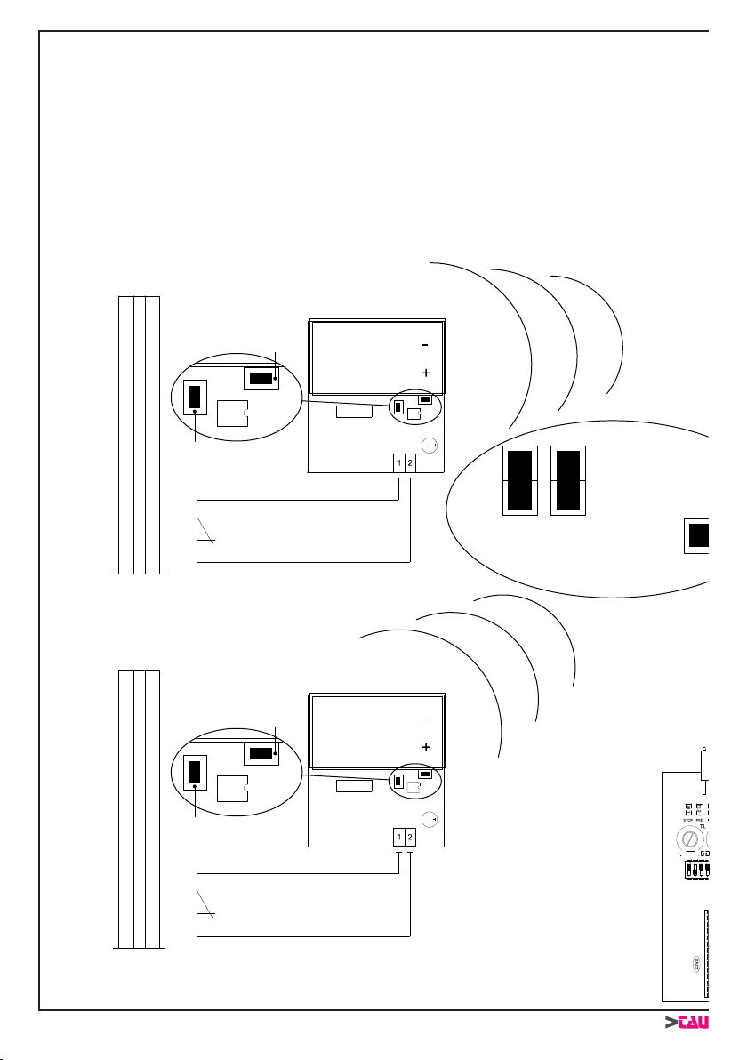
g. 4
SCHEMA CABLAGGIO DELLA BASE TWM AD UNA CENTRALE PER MOTORI IN 12V
WIRING DIAGRAM OF TWM BASE TO A CONTROL UNIT FOR 12V MOTORS
VERKABELUNGSSCHEMA DER TWM-BASIS AN EINER STEUERUNG FÜR MOTOREN IN 12V
SCHÉMA DE CÂBLAGE ENTRE LA BASE TWM ET UNE LOGIQUE DE COMMANDE POUR
MOTEURS EN 12 V
ESQUEMA DEL CABLEADO DE LA BASE TWM A UNA CENTRAL PARA MOTORES DE 12V
TWM
TWC
BORDO SENSIBILE FISSO
FIXED SENSITIVE EDGE
FESTE SCHALTLEISTE
BORD SENSIBLE FIXE
BORDE SENSIBLE FIJO
BORDO SENSIBILE MOBILE
MOBILE SENSITIVE EDGE
BEWEGLICHE SCHALTLEISTE
BORD SENSIBLE MOBILE
BORDE SENSIBLE MÓVIL TWC
Tasto programmazione
Programming pushbutton
Programmierungstaste
Touche programmation
Tecla programación
Cancellazione programmazione
Programming cancellation
Programmierung löschen
Effacement programmation
Anulación programación
Tasto programmazione
Programming pushbutton
Programmierungstaste
Touche programmation
Tecla programación
Cancellazione programmazione
Programming cancellation
Programmierung löschen
Effacement programmation
Anulación programación
Collegare in serie il contatto di una
eventuale fotocellula tradizionale
Connect the contact in series
to any traditional photocell
Den Kontakt einer eventuellen herkömmlichen
Photozelle in Reihenschaltung verbinden
Connecter en série le contact d’une
éventuelle photocellule traditionnelle
Conecte en serie el contacto de una
eventual fotocélula tradicional
Collegare in serie il contatto di un
eventuale bordo sensibile
Connect the contact in series
to any sensitive edge
Den Kontakt einer eventuellen Schaltleiste
in Reihenschaltung verbinden
Connecter en série le contact
d’un éventuel bord sensible
Conecte en serie el contacto de un
eventual borde sensible
Tasto programmazione
Programming pushbutton
Programmierungstaste
Touche programmation
Tecla programación
PORTA BATTERIE AA 2x1,5V
BATTERY HOLDER AA 2X1.5 V
BATTERIEKASTEN AA 2x1,5V
LOGEMENT BATTERIES AA 2x1,5V
SOPORTE BATERÍAS AA 2x1,5V
PORTA BATTERIE AA 2x1,5V
BATTERY HOLDER AA 2X1.5 V
BATTERIEKASTEN AA 2x1,5V
LOGEMENT BATTERIES AA 2x1,5V
SOPORTE BATERÍAS AA 2x1,5V
Contatto N.C. (Normalmente Chiuso)
NC contact (Normally Closed)
N.C.-Kontakt (Gewöhnlich geschlossen)
Contact N.F. (Normalement Fermé)
Contacto N.C. (Normalmente Cerrado)
Contatto N.C. (Normalmente Chiuso)
NC contact (Normally Closed)
N.C.-Kontakt (Gewöhnlich geschlossen)
Contact N.F. (Normalement Fermé)
Contacto N.C. (Normalmente Cerrado)
DL8 DL7 DL6 DL5 DL4 DL3 DL2 DL1 DL9
J3J2
J4
DV2
DV1
LP
PP
FOT2
FOT1
CM
CF
PRG
J3J2
J4

17
TAU-WIRELESS
g. 4
TWM
TWC
BORDO SENSIBILE FISSO
FIXED SENSITIVE EDGE
FESTE SCHALTLEISTE
BORD SENSIBLE FIXE
BORDE SENSIBLE FIJO
BORDO SENSIBILE MOBILE
MOBILE SENSITIVE EDGE
BEWEGLICHE SCHALTLEISTE
BORD SENSIBLE MOBILE
BORDE SENSIBLE MÓVIL TWC
Tasto programmazione
Programming pushbutton
Programmierungstaste
Touche programmation
Tecla programación
Cancellazione programmazione
Programming cancellation
Programmierung löschen
Effacement programmation
Anulación programación
Tasto programmazione
Programming pushbutton
Programmierungstaste
Touche programmation
Tecla programación
Cancellazione programmazione
Programming cancellation
Programmierung löschen
Effacement programmation
Anulación programación
Collegare in serie il contatto di una
eventuale fotocellula tradizionale
Connect the contact in series
to any traditional photocell
Den Kontakt einer eventuellen herkömmlichen
Photozelle in Reihenschaltung verbinden
Connecter en série le contact d’une
éventuelle photocellule traditionnelle
Conecte en serie el contacto de una
eventual fotocélula tradicional
Collegare in serie il contatto di un
eventuale bordo sensibile
Connect the contact in series
to any sensitive edge
Den Kontakt einer eventuellen Schaltleiste
in Reihenschaltung verbinden
Connecter en série le contact
d’un éventuel bord sensible
Conecte en serie el contacto de un
eventual borde sensible
Tasto programmazione
Programming pushbutton
Programmierungstaste
Touche programmation
Tecla programación
PORTA BATTERIE AA 2x1,5V
BATTERY HOLDER AA 2X1.5 V
BATTERIEKASTEN AA 2x1,5V
LOGEMENT BATTERIES AA 2x1,5V
SOPORTE BATERÍAS AA 2x1,5V
PORTA BATTERIE AA 2x1,5V
BATTERY HOLDER AA 2X1.5 V
BATTERIEKASTEN AA 2x1,5V
LOGEMENT BATTERIES AA 2x1,5V
SOPORTE BATERÍAS AA 2x1,5V
Contatto N.C. (Normalmente Chiuso)
NC contact (Normally Closed)
N.C.-Kontakt (Gewöhnlich geschlossen)
Contact N.F. (Normalement Fermé)
Contacto N.C. (Normalmente Cerrado)
Contatto N.C. (Normalmente Chiuso)
NC contact (Normally Closed)
N.C.-Kontakt (Gewöhnlich geschlossen)
Contact N.F. (Normalement Fermé)
Contacto N.C. (Normalmente Cerrado)
DL8 DL7 DL6 DL5 DL4 DL3 DL2 DL1 DL9
J3J2
J4
DV2
DV1
LP
PP
FOT2
FOT1
CM
CF
PRG
J3J2
J4
18
TAU-WIRELESS
g. 5
SCHEMA CABLAGGIO DELLA BASE TWM AD UNA CENTRALE PER MOTORI IN 230V
WIRING DIAGRAM OF TWM BASE TO A CONTROL UNIT FOR 230V MOTORS
VERKABELUNGSSCHEMA DER TWM-BASIS AN EINER STEUERUNG FÜR MOTOREN IN 230V
SCHÉMA DE CÂBLAGE ENTRE LA BASE TWM ET UNE LOGIQUE DE COMMANDE POUR
MOTEURS EN 230 V
ESQUEMA DEL CABLEADO DE LA BASE TWM A UNA CENTRAL PARA MOTORES DE 230V
TWM
BORDO SENSIBILE FISSO
FIXED SENSITIVE EDGE
FESTE SCHALTLEISTE
BORD SENSIBLE FIXE
BORDE SENSIBLE FIJO
BORDO SENSIBILE MOBILE
MOBILE SENSITIVE EDGE
BEWEGLICHE SCHALTLEISTE
BORD SENSIBLE MOBILE
BORDE SENSIBLE MÓVIL
Collegare in serie il contatto di una
eventuale fotocellula tradizionale
Connect the contact in series
to any traditional photocell
Den Kontakt einer eventuellen herkömmlichen
Photozelle in Reihenschaltung verbinden
Connecter en série le contact d’une
éventuelle photocellule traditionnelle
Conecte en serie el contacto de una
eventual fotocélula tradicional
Tasto programmazione
Programming pushbutton
Programmierungstaste
Touche programmation
Tecla programación
Collegare in serie il contatto di un
eventuale bordo sensibile
Connect the contact in series
to any sensitive edge
Den Kontakt einer eventuellen Schaltleiste
in Reihenschaltung verbinden
Connecter en série le contact
d’un éventuel bord sensible
Conecte en serie el contacto de un
eventual borde sensible
DL8 DL7 DL6 DL5 DL4 DL3 DL2 DL1 DL9
J3J2
DV2
DV1
LP
PP
FOT2
FOT1
CM
CF
PRG
TWC
Tasto programmazione
Programming pushbutton
Programmierungstaste
Touche programmation
Tecla programación
Cancellazione programmazione
Programming cancellation
Programmierung löschen
Effacement programmation
Anulación programación
PORTA BATTERIE AA 2x1,5V
BATTERY HOLDER AA 2X1.5 V
BATTERIEKASTEN AA 2x1,5V
LOGEMENT BATTERIES AA 2x1,5V
SOPORTE BATERÍAS AA 2x1,5V
Contatto N.C. (Normalmente Chiuso)
NC contact (Normally Closed)
N.C.-Kontakt (Gewöhnlich geschlossen)
Contact N.F. (Normalement Fermé)
Contacto N.C. (Normalmente Cerrado)
TWC
Tasto programmazione
Programming pushbutton
Programmierungstaste
Touche programmation
Tecla programación
Cancellazione programmazione
Programming cancellation
Programmierung löschen
Effacement programmation
Anulación programación PORTA BATTERIE AA 2x1,5V
BATTERY HOLDER AA 2X1.5 V
BATTERIEKASTEN AA 2x1,5V
LOGEMENT BATTERIES AA 2x1,5V
SOPORTE BATERÍAS AA 2x1,5V
Contatto N.C. (Normalmente Chiuso)
NC contact (Normally Closed)
N.C.-Kontakt (Gewöhnlich geschlossen)
Contact N.F. (Normalement Fermé)
Contacto N.C. (Normalmente Cerrado)
J3J2
J4
J4

19
TAU-WIRELESS
g. 5
TWM
BORDO SENSIBILE FISSO
FIXED SENSITIVE EDGE
FESTE SCHALTLEISTE
BORD SENSIBLE FIXE
BORDE SENSIBLE FIJO
BORDO SENSIBILE MOBILE
MOBILE SENSITIVE EDGE
BEWEGLICHE SCHALTLEISTE
BORD SENSIBLE MOBILE
BORDE SENSIBLE MÓVIL
Collegare in serie il contatto di una
eventuale fotocellula tradizionale
Connect the contact in series
to any traditional photocell
Den Kontakt einer eventuellen herkömmlichen
Photozelle in Reihenschaltung verbinden
Connecter en série le contact d’une
éventuelle photocellule traditionnelle
Conecte en serie el contacto de una
eventual fotocélula tradicional
Tasto programmazione
Programming pushbutton
Programmierungstaste
Touche programmation
Tecla programación
Collegare in serie il contatto di un
eventuale bordo sensibile
Connect the contact in series
to any sensitive edge
Den Kontakt einer eventuellen Schaltleiste
in Reihenschaltung verbinden
Connecter en série le contact
d’un éventuel bord sensible
Conecte en serie el contacto de un
eventual borde sensible
DL8 DL7 DL6 DL5 DL4 DL3 DL2 DL1 DL9
J3J2
DV2
DV1
LP
PP
FOT2
FOT1
CM
CF
PRG
TWC
Tasto programmazione
Programming pushbutton
Programmierungstaste
Touche programmation
Tecla programación
Cancellazione programmazione
Programming cancellation
Programmierung löschen
Effacement programmation
Anulación programación
PORTA BATTERIE AA 2x1,5V
BATTERY HOLDER AA 2X1.5 V
BATTERIEKASTEN AA 2x1,5V
LOGEMENT BATTERIES AA 2x1,5V
SOPORTE BATERÍAS AA 2x1,5V
Contatto N.C. (Normalmente Chiuso)
NC contact (Normally Closed)
N.C.-Kontakt (Gewöhnlich geschlossen)
Contact N.F. (Normalement Fermé)
Contacto N.C. (Normalmente Cerrado)
TWC
Tasto programmazione
Programming pushbutton
Programmierungstaste
Touche programmation
Tecla programación
Cancellazione programmazione
Programming cancellation
Programmierung löschen
Effacement programmation
Anulación programación PORTA BATTERIE AA 2x1,5V
BATTERY HOLDER AA 2X1.5 V
BATTERIEKASTEN AA 2x1,5V
LOGEMENT BATTERIES AA 2x1,5V
SOPORTE BATERÍAS AA 2x1,5V
Contatto N.C. (Normalmente Chiuso)
NC contact (Normally Closed)
N.C.-Kontakt (Gewöhnlich geschlossen)
Contact N.F. (Normalement Fermé)
Contacto N.C. (Normalmente Cerrado)
J3J2
J4
J4

20
TAU-WIRELESS
- - -- - - - - - - - - - - - - - - - - - - - - - - - - - - - - - - - - - - - - - - - - - - - - - - - - - - - - - - - - - - - - - - - - - - - - - - - - - - - -
g. 2
This manual suits for next models
1
Table of contents
Other tau Gate Opener manuals


