tau 700BRCTR User manual

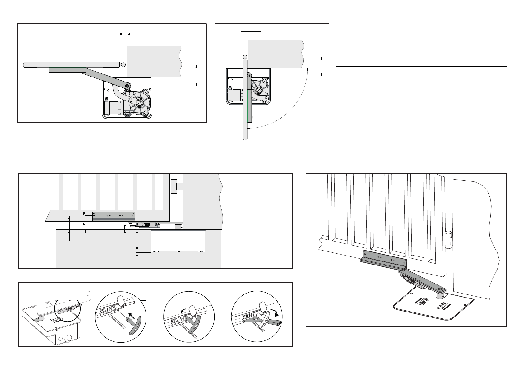
MAX 20 cm
MAX 3 cm
66
mm
43
3mm
3
4
1
5
2
g. 2
g. 1
A
A
2
1
g. 3
A
A
STEP 3
A
A
STEP 1
STEP 2
g. 4
BRACCIO PER MONTAGGIO FUORI ASSE PER R18
ARM FOR MISALIGNED MOUNTING FOR R18
ARM FÜR AUßERACHSIGE MONTAGE FÜR R18
BRAS POUR MONTAGE DÉSAXÉ POUR R18
BRAZO PARA MONTAJE DESCENTRADO PARA R18
700BRCTR
TAU srl - Via Enrico Fermi, 43 - 36066 Sandrigo (VI) - Italy
Tel +39 0444 750190 - Fax +39 0444 750376 - www.tauitalia.com
D-MNL0BRCTR 15-11-22 - Rev.00
Foglietto illustrativo
CARTA - Raccolta dierenziata. Segui le indicazioni del tuo comune. (N.B.: togliere i punti metallici)
Instruction leaet
PAPER - Waste separation. Follow the instructions of your city hall. (Note: remove the staples)
22
PAP
PER SBLOCCARE:
TO UNLOCKING:
ASTEP 3
A
A
A
STEP 1 STEP 2
170
MAX
30
MIN
90
170
MAX
30
MIN
LIVELLO
PAVIMENTO
FINITO
58
4
155
8
43
g. 2
g. 1A
g. 1B
g. 3
BRACCIO PER MONTAGGIO FUORI ASSE PER R30/R40
ARM FOR MISALIGNED MOUNTING FOR R30/R40
ARM FÜR AUßERACHSIGE MONTAGE FÜR R30/R40
BRAS POUR MONTAGE DÉSAXÉ POUR R30/R40
BRAZO PARA MONTAJE DESCENTRADO PARA R30/R40
g. 4
PER SBLOCCARE:
TO UNLOCKING:

NOTE PER L’INSTALLATORE:
- Montare il braccio il più vicino possibile
all’asse del cardine del cancello.
- Il dispositivo in oggetto richiede un’a-
nalisi dei rischi accurata: maggiore è il
disassamento e più grande è la zona di
pericolo (rischio di cesoiamento).
LIMITI D’IMPIEGO
Il braccio BRC18 può essere installato nei
limiti di disassamento consentiti (g. 1).
ISTRUZIONI PER IL MONTAGGIO
1) Vericare l’ecienza delle parti sse e
mobili della struttura che sarà automa-
tizzata.
2) Eseguire lo scavo sulla base delle misure
riportate in g. 2 nella posizione deside-
rata.
3) Collocare la cassa di fondazione (1 g.
2) all’interno dello scavo.
4) Posizionare il motoriduttore nella cassa
e bloccarlo con le 4 viti fornite unita-
mente ad esso.
5) Inserire un tubo per il drenaggio dell’ac-
qua utilizzando il foro praticato sulla
cassa (3 g. 2).
NOTA: SI FA ASSOLUTO DIVIETO DI
COLLEGARE IL TUBO DI DRENAGGIO
DELL'ACQUA CON QUALSIASI IMPIAN-
TO DI SCARICO SIA CIVILE CHE INDU-
STRIALE TIPO FOGNATURE (ACQUE
NERE). COLLEGARSI EVENTUALMENTE
ALL'IMPIANTO DI SCARICO DI ACQUE
PIOVANE (ACQUE BIANCHE).
6) Inserire una guaina spiralata per il pas-
saggio dei cavi motore usando il foro
sulla cassa (4 g. 2).
7) Gettare (il calcestruzzo) all’interno dello
scavo; curare la messa in bolla della
cassa che deve sporgere dal livello del
pavimento nito di 3 mm (= spessore
del coperchio - 2 g. 2).
8) Montare tutti gli organi di collegamento.
9) Fissare il binario di scorrimento (1 g.
3) al cancello CHIUSO e in linea con il
bordo inferiore del cancello (A g. 2).
Il cuscinetto deve essere a lo con il
binario (A g. 3).
10) La piastra forata in dotazione (2 g. 3)
permette un migliore ancoraggio del
binario (es. con cancelli in legno, etc.).
SBLOCCO MANUALE
Per sbloccare (operazione da eettuare a
motore fermo):
1) Aprire il tappo in gomma dalla leva di
sblocco (g.4);
2) inlare la chiave (g.4);
3) ruotare nel senso indicato in gura 4 e
tirare o spingere la leva. Quindi aprire il
battente del cancello manualmente.
Italiano English Deutsch Français Español
INSTALLER’S NOTES:
- Fit the arm as close as possible to the
gate hinge.
- The said device requires a thorough risk
analysis: the greater the misalignment
the greater is the danger zone (risk of
shearing).
USAGE LIMITS
The BRC18 arm can be tted within the per-
mitted misalignment limits (g. 1).
ASSEMBLY INSTRUCTIONS
1) Check that the xed and moving parts of
the structure which is to be automated
are in good working order.
2) Dig the hole, in the desired position
following the measurements indicated
in g. 3.
3) Place the foundation box (1 g. 2) inside
the hole.
4) Place the gearmotor in the box and
fasten it using the 4 screws supplied.
5) Insert a drainpipe through the hole in
the box (3 g. 2).
WARNING: IT IS SEVERELY PROHIBITED
TO CONNECT THE WATER DRAINAGE
PIPE TO ANY KIND OF DRAINAGE SYS-
TEM, BE IT CIVIL OR AN INDUSTRIAL
SEWAGE PLANT (BLACK WATER). IF
NECESSARY, THE PIPE CAN BE CON-
NECTED TO A RAINWATER DRAINAGE
SYSTEM (WHITE WATER).
6) Insert a spiral sheath for the passage of
the motor cables through the hole in the
box (4 g. 2).
7) Lay (the concrete) in the hole and care-
fully align the box which must protrude
to 3 mm above the level of the nished
ooring (= cover thickness - 2 Figure 2).
8) Assemble all the connection compo-
nents.
9) Fix the track (1 g. 3) to the CLOSED
gate and in line with the lower edge of
the gate (A g. 2). The bearing must be
ush with the track (A g. 3).
10) The supplied drilled plate (2 g. 3) per-
mits a more secure xing of the track
(e.g. with wooden gates, etc.).
MANUAL RELEASE
To unlock (operation to be carried out with
the motor stopped):
1) Open the rubber cap from the release
lever (g.4);
2) insert the key (g. 4);
3) rotate in the direction shown in gure
4 and pull or push the lever. Then open
the gate leaf manually.
HINWEISE FÜR DEN INSTALLATEUR:
- Den Arm so nah wie möglich an die Achse
des Torangelzapfens montieren.
- Die genannte Vorrichtung erfordert eine
sorgfältige Risikoanalyse: je größer die
Nichtuchtung ist, umso größer ist der
Gefahrenbereich (Schnittgefahr).
EINSATZGRENZEN
Der Arm BRC18 kann innerhalb der zu-
lässigen Nichtuchtungsgrenzen installiert
werden (Abb. 1).
MONTAGEANWEISUNGEN
1) Die Ezienz der festen und beweglichen
Teile der zu automatisierenden Struktur
überprüfen.
2) Die Ausgrabung auf der Grundlage der
Maße in Abb. 2 an der gewünschten
Stelle ausführen.
3) Den Fundamentkasten (1, Abb. 2) in der
Ausgrabung so anbringen.
4) Den Getriebemotor im Kasten an-
bringen und mit den 4 mitgelieferten
Schrauben befestigen.
5) Einen Drainageschlauch für das Wasser
einfügen, hierzu das Loch am Kasten
verwenden (3, Abb. 2).
ANMERKUNG: ES IST ABSOLUT VER-
BOTEN, DEN DRAINAGESCHLAUCH
DES WASSERS AN EINE ZIVI-LE ODER
INDUSTRIELLE SCHMUTZWASSER-
ABFLUSSANLAGE ANZUSCHLIEßEN;
DEN SCHLAUCH GGF. AN DIE REGEN-
WASSER-ABFLUSSANLAGE (KLARES
WASSER) ANSCHLIEßEN.
6) Einen Spiralmantel für die Durchfüh-
rung der Motorkabel einfügen, hierzu
das Loch am Kasten verwenden (4, Abb.
2).
7) In Beton versenken und auf die Nivel-
lierung des Fundamentkastens achten,
der 3 mm über den fertigen Fußboden
herausragen muss (= Dicke des Deckels
– 2, Abb. 2).
8) Alle Verbindungselemente montieren.
9) Die Gleitschiene (1, Abb. 3) am GE-
SCHLOSSENEN Tor und auf derselben
Linie der unteren Torkante (A, Abb. 2)
befestigen. Das Lager muss mit der
Schiene abschneiden (A, Abb. 3).
10) Die mitgelieferte Lochplatte (2, Abb. 3)
ermöglicht eine bessere Verankerung
der Schiene (z. B. mit Holztoren, usw. ).
MANUELLE ENTRIEGELUNG
Entriegeln (darf nur bei stehendem Motor
gemacht werden):
1) den Plastikverschluss des ans Tor gesch-
weißten Hebels entfernen (Abb. 4);
2) den Steckschlüssel (Abb. 4) in den Tor-
hebel stecken;
3) in der in Abb. 4 gezeigten Richtung
drehen, dann den Torügel von Hand
önen.
NOTES POUR L’INSTALLATEUR :
- Monter le bras le plus près possible de
l’axe du gond du portail.
- Le dispositif en objet demande une
analyse approfondie des risques : plus
le désaxement est important et plus la
zone de danger est grande (risque de
cisaillement).
LIMITES D’UTILISATION
Le bras BRC18 peut être installé dans les
limites de désaxement autorisées (g. 1).
INSTRUCTIONS DE MONTAGE
1) Vérier l’ecacité des parties xes et
mobiles de la structure destinée à être
automatisée.
2) Creuser le trou à l’emplacement désiré
suivant les mesures indiquées dans la
g. 2.
3) Placer la caisse de fondation (1 g. 2)
dans le trou.
4) Positionner le motoréducteur dans le
caisson de fondation et le bloquer avec
les 4 vis fournies.
5) Introduire un tube pour le drainage de
l’eau en utilisant le trou sur le caisson
(3 g. 2).
NOTE : IL EST ABSOLUMENT INTER-
DIT DE RACCORDER LE TUYAU DE
DRAINAGE DE L’EAU À UN RÉSEAU
D’ÉVACUATION, CIVIL OU INDUSTRIEL
TYPE ÉGOUT (EAUX USÉES). EFFECTUER
ÉVENTUELLEMENT LE RACCORDEMENT
AU RÉSEAU PLUVIAL (EAUX ATMOS-
PHÉRIQUES).
6) Introduire une gaine spiralée pour le
passage des câbles moteur en utilisant
le trou sur le caisson (4 g. 2).
7) Couler le ciment à l’intérieur du trou ;
veiller à mettre de niveau le caisson qui
doit dépasser du niveau du sol ni de 3
mm (= épaisseur du couvercle - 2 g. 2).
8) Monter tous les organes de liaison.
9) Fixer le rail de coulissement (1 g. 3) au
portail FERMÉ et aligné avec le bord in-
férieur du portail (A g. 2). Le roulement
doit être à eur du rail (A g. 3).
10) La plaque perforée fournie (2 fig. 3)
permet un meilleur ancrage du rail (par
ex. avec les portails en bois, etc.).
DÉBLOCAGE MANUEL
Pour débloquer (opération à eectuer avec
le moteur à l’arrêt) :
1) enlever le bouchon en plastique du levier
soudé au portail (g.4) ;
2) enler la clé à tube (g.4) dans le levier
du portail ;
3) tourner dans le sens indiqué sur la g. 4
puis ouvrir manuellement le portail.
NOTAS PARA EL INSTALADOR:
- Monte el brazo lo más cerca posible del
eje del gozne de la cancela.
- El dispositivo en cuestión necesita un
análisis preciso de los riesgos: mayor es
la desalineación de los ejes y mayor es la
zona de peligro (riesgo de corte).
LÍMITES DE EMPLEO
El brazo BRC18 se puede instalar en los límites
permitidos de desalineación de los ejes (g. 1).
INSTRUCCIONES PARA EL MONTAJE
1) Verique la ecacia de las partes jas y
móviles de la estructura que se automa-
tizará.
2) Efectúe la excavación basándose en las
medidas que se muestran en la g. 2 y
en la posición deseada.
3) Coloque la caja de cimentación (1 g. 2)
en el interior de la excavación.
4) Coloque el motorreductor en la caja
y bloquéelo con los 4 tornillos que se
entregan junto con el motorreductor.
5) Introduzca un tubo para el desagüe del
agua utilizando el orificio efectuado
sobre la caja (3 g. 2).
NOTA: QUEDA TERMINANTEMENTE
PROHIBIDO CONECTAR EL TUBO DE
DRENAJE DEL AGUA CON CUALQUIER
INSTALACIÓN DE DESCARGA, TANTO
CIVIL COMO INDUSTRIAL, DE TIPO
ALCANTARILLADO (AGUAS NEGRAS).
CONÉCTESE EVENTUALMENTE A LA
INSTALACIÓN DE DESCARGA DE AGUAS
PLUVIALES (AGUAS BLANCAS).
6) Introduzca una vaina helicoidal para
pasar los cables del motor utilizando el
oricio sobre la caja (4 g. 2).
7) Tire (el hormigón) en el interior del agu-
jero; es necesario que coloque la caja
de forma que sobresalga del nivel del
suelo acabado unos 3 mm (= grosor de
la tapa - 2 g. 2).
8) Monte todos los órganos de conexión.
9) Sujete el carril de deslizamiento (1 g. 3)
a la cancela CERRADA y alineada con el
borde inferior de la cancela (A g. 2). El
cojinete tiene que estar situado alineado
con el carril (A g. 3).
10) La placa agujereada presente en el equi-
pamiento de base (2 g. 3) permite un
anclaje mejor del carril (ej. con cancelas
de madera, etc.).
DESBLOQUEO MANUAL
Para el desbloqueo (operación que se debe
efectuar con el motor detenido):
1) quite el tapón de plástico de la palanca
soldada a la cancela (g.4);
2) introduzca la llave de tubo (g.4) en la
palanca de la cancela;
3) gire hacia el sentido indicado en la gura 4,
y abra la hoja de la cancela manualmente.
Other tau Gate Opener manuals


