tau SPEED User manual

1
Serie SPEED
MANUALE D’USO E MANUTENZIONE
USE AND MAINTENANCE MANUAL
BEDIENUNGS - UND WARTUNGSANLEITUNG
MANUEL D’EMPLOI ET D’ENTRETIEN
MANUAL DE USO Y MANTENIMIENTO
SPEED
Automatismo per Cancelli Scorrevoli - Uso Residenziale/Condominiale
Sliding Gate Operator - Residential/Communities
Schiebetorantrieb für Privat und Gewerbe
Automatisme pour Portails Coulissants – Usage Résidentiel/Intensif
Accionador para Puertas Correderas – Uso Residencial/Comunidades
Via Enrico Fermi, 43 - 36066 Sandrigo (VI) Italia
Tel +39 0444 750190 - Fax +39 0444 750376 - info@tauitalia.com - www.tauitalia.com
IT - Istruzioni originali
D-MNL0SPEED 01-12-2014 - Rev.25

2
Serie SPEED
Italiano
English
La Casa costruttrice si riserva il diritto di apportare modiche o miglioramenti al prodotto senza alcun preavviso. Eventuali imprecisioni o errori
riscontrabili nel presente fascicolo, saranno corretti nella prossima edizione.
All’apertura dell’imballo vericare che il prodotto sia integro. Riciclare i materiali secondo la normativa vigente.
I disegni esplosi presenti nelle ultime pagine delle presenti istruzioni sono puramente indicativi. Per i ricambi fare riferimento al relativo
listino.
Tau si congratula per la scelta del prodotto e vi invita a leggere con molta attenzione queste pagine.
Al ne di renderle semplici, le istruzioni sono state impaginate seguendo l’ordine delle varie fasi d’installazione dell’impianto.
Tutto quello che non è espressamente previsto nel presente manuale NON è permesso.
Usi non indicati, infatti, potrebbero essere causa di danni al prodotto stesso e mettere in pericolo persone, animali e/o cose.
L’installazione deve essere eseguita da personale qualicato, professionalmente competente.
L’installazione, i collegamenti elettrici e le regolazioni devono essere effettuati nell’osservanza della Buona Tecnica e in ottemperanza alle
norme vigenti.
Prima di iniziare l’installazione vericare l’integrità del prodotto.
Non installare il prodotto in ambiente e atmosfera esplosivi.
Prima di installare l’automazione, apportare tutte le modiche strutturali relative alla realizzazione dei franchi di sicurezza ed alla protezione
o segregazione di tutte le zone di schiacciamento, cesoiamento, convogliamento e di pericolo in genere. Vericare che la struttura esistente
abbia i necessari criteri di robustezza e stabilità.
I dispositivi di sicurezza (fotocellule, coste sensibili, stop di emergenza, ecc.) devono essere installati tenendo in considerazione: le normative
e le direttive in vigore, i criteri della Buona Tecnica, l’ambiente di installazione, la logica di funzionamento del sistema e le forze sviluppate dalla
porta o cancello motorizzati.
Applicare le segnalazioni previste dalle norme vigenti per individuare le zone pericolose. Ogni installazione deve riportare in modo visibile
l’indicazione dei dati identicativi degli organi automatizzati.
Prima di collegare l’alimentazione elettrica accertarsi che i dati di targa siano rispondenti a quelli della rete di distribuzione elettrica.
Prevedere sulla rete di alimentazione un interruttore/sezionatore onnipolare con distanza d’apertura dei contatti uguale o superiore a 3 mm.
Vericare che a monte dell’impianto elettrico vi siano un interruttore differenziale e una protezione di sovracorrente adeguati (interruttore
magnetotermico C6).
Collegare l’automazione a un’efcace impianto di messa a terra eseguito come previsto dalle vigenti norme di sicurezza.
Il costruttore dell’automazione declina ogni responsabilità qualora vengano installati componenti incompatibili ai ni della sicurezza e del buon
funzionamento. Per l’eventuale riparazione o sostituzione dei prodotti dovranno essere utilizzati esclusivamente ricambi originali.
L’installatore deve fornire tutte le informazioni relative al funzionamento automatico, manuale e di emergenza della struttura automatizzata, e
consegnare all’utilizzatore dell’impianto le istruzioni per l’uso.
The manufacturer reserves the right to modify or improve products without prior notice. Any inaccuracies or errors found in this handbook
will be corrected in the next edition.
When opening the packing please check that the product is intact. Please recycle materials in compliance with current regulations.
Congratulations on choosing this Tau product. Please read this handbook carefully.
For the sake of simplicity, the instructions are listed in order of installation.
Anything not expressly specied in this handbook is FORBIDDEN.
Operations not indicated in these instructions may damage the product and put people, animals and/or and property at risk.
The equipment should be installed only by trained and qualied personnel.
Installation, electrical connections and adjustments must be made according to the rules of good workmanship and current standards.
Before beginning installation, make sure the product is undamaged.
Do not install the product in explosive environments.
Prior to installing the automation, make all structural modications in order to ensure safety distances and protect and segregate areas
in which people may be exposed to the risk of crushing, shearing, dragging or similar dangers. Make sure the existing structure is
sufciently sturdy and stable.
The safety devices (photocells, sensitive edges, emergency stop devices, etc.) must be installed according to current legislation and
directives, the rules of good workmanship, the installation area, the operating logic of the system and the forces developed by the
powered door or gate.
Fit the signs required by current regulations for identifying dangerous areas. Each installation must show the identication data of the
automated devices in a visible place.
Before connecting to the power supply, make sure the data on the rating plate correspond to the mains power supply.
Fit a multipole switch/knife switch on the power supply network with contacts opening distance of at least 3 mm.
Make sure there is a suitable circuit breaker and overcurrent protection device (thermal-magnet breaker C6) upline from the electrical
system.
Connect the automation to an efcient earth system compliant with current safety standards.
The manufacturer declines all liability if incompatible safety and components are installed. Only use original spare parts to repair or
replace the product.
The tter must provide all the information relative to the automatic, manual and emergency operation of the automated unit, and give
the user the operating instructions.
The exploded views on the last pages of this instruction manual are purely indicative. For the spare parts, please refer to the relevant
price list.

3
Serie SPEED
Français
Deutsch
Der Hersteller behält sich das Recht vor, ohne vorherige Benachrichtung Änderungen oder Verbesserungen am Produkt anzubringen.
Ungenauigkeiten oder Fehler, die in der vorliegenden Ausgabe festgestellt werden, werden in der nächsten Ausgabe berichtigt.
Beim Öffnen der Verpackung prüfen, dass das Produkt keine Schäden aufweist. Die Materialien nach den gültigen Vorschriften recyclen.
Die explodierten Zeichnungen auf den letzten Seiten dieser Anleitung sind nur anzeigend. Für die Ersatzteile, bitte die entsprechende Preisliste
sehen.
Tau gratuliert Ihnen zur Wahl dieses Produkts und bittet Sie, diese Seiten sehr aufmerksam zu lesen.
Um die Anweisungen einfach zu machen, wurden sie in der Reihenfolge der verschiedenen Installationsphasen der Anlage verfasst.
Alles nicht ausdrücklich in diesen Anleitungen vorgesehene ist UNZULÄSSIG.
Ein nicht angegebener Gebrauch könnte Schäden am Produkt verursachen und Personen, Tiere und/oder Gegenstände in Gefahr bringen.
Die Installation muss von beruich kompetentem Fachpersonal ausgeführt werden.
Installation, elektrische Anschlüsse und Einstellungen sind unter Beachtung der Fachtechnik und der gültigen Vorschriften auszuführen.
Das Produkt vor der Installation auf Schäden überprüfen.
Das Produkt nicht in EX-Umgebung bzw. EX-Atmosphäre installieren.
Vor der Installation der Automatisierung alle strukturellen Änderungen für das Vorhandensein der Sicherheitsabstände und den Schutz aller
Bereiche ausführen, in denen Quetsch-, Schnitt- und Mitnehmgefahr und Gefahren allgemein bestehen. Prüfen, ob die vorhandene Struktur
die erforderliche Robustheit und Stabilität besitzt.
Sicherheitsvorrichtungen (Fotozellen, Sicherheitsleisten, Notstop usw.) müssen unter Berücksichtigung des folgenden installiert werden: gültige
Vorschriften und Verordnungen, korrekte Fachtechnik, Installationsumgebung, Betriebslogik des Systems und Kräfte, die vom motorbetriebenen
Tor entwickelt werden.
Zur Kennzeichnung von Gefahrenbereichen die laut gültigen Vorschriften vorgesehenen Beschilderungen anbringen. An jeder Installation
müssen die Kenndaten der automatisierten Elemente sichtbar angegeben sein.
Vor dem Anschluss der Stromversorgung ist sicher zu stellen, dass die Kenndaten mit jenen des Stromnetzes übereinstimmen.
Am Versorgungsnetz einen allpoligen Schalter/Trennschalter mit Öffnungsabstand der Kontakte von oder über 3 mm vorsehen.
Prüfen, dass vor der elektrischen Anlage ein Differentialschalter und ein geeigneter Überstromschutz (magnetothermischer Schalter C6)
vorhanden sind.
Die Automatisierung an eine wirksame Erdungsanlage anschließen, die nach den gültigen Sicherheitsvorschriften ausgeführt ist.
Der Hersteller der Automatisierung übernimmt keinerlei Haftung, falls Bestandteile installiert werden, die – was Sicherheit und korrekten Betrieb
betrifft – nicht kompatibel sind. Zur Reparatur oder zum Ersatz der Produkte dürfen ausschließlich Originalersatzteile verwendet werden.
Der Installateur hat alle Auskünfte über den automatischen und manuellen Betrieb und den Notbetrieb der automatisierten Struktur zu liefern
und muss dem Benutzer der Anlage die Bedienungsanweisungen aushändigen.
Le Constructeur se réserve le droit d’apporter des modications ou des améliorations au produit sans aucun préavis. Les éventuelles imprécisions ou
erreurs présentes dans ce fascicule seront corrigées dans la prochaine édition.
À l’ouverture de l’emballage, vérier que le produit est intact. Recycler les matériaux suivant les normes en vigueur.
Les plans “esplosi non lo so” qui se trouvent sur les dernières pages de ces notices techniques sont à titre indicatif. En ce qui concerne les pièces
détachées consulter la liste relative.
Tau vous félicite de votre choix et vous invite à lire très attentivement les pages qui suivent.
An de faciliter la compréhension, l’ordre de présentation des instructions suit celui des différentes phases d’installation de l’automatisme.
Tout ce qui n’est pas expressément prévu dans ce manuel N’EST PAS permis.
Les utilisations non indiquées, en effet, pourraient provoquer des dommages au produit et mettre en danger les personnes, les animaux et/ou
les choses.
L’installation doit être effectuée par du personnel qualié, professionnellement compétent.
L’installation, les connexions électriques et les réglages doivent être effectués dans les règles de l’art en respectant les normes en vigueur.
Avant de commencer l’installation, vérier l’intégrité du produit.
Ne pas installer le produit dans un environnement et une atmosphère explosifs.
Avant d’installer l’automatisme, apporter toutes les modications structurelles relatives à la réalisation des espaces de sécurité et à la
protection ou à l’isolement de toutes les zones d’écrasement, cisaillement et de danger en général. Vérier que la structure existante possède
la robustesse et la stabilité nécessaires.
Les dispositifs de sécurité (photocellules, barres palpeuses, arrêt d’urgence, etc.) doivent être installés en tenant compte : des normes et des
directives en vigueur, des règles de l’art, du site d’installation, de la logique de fonctionnement du système et des forces générées par la porte
ou le portail motorisés.
Appliquer les signalisations prévues par les normes en vigueur pour identier les zones dangereuses. Chaque installation doit reporter de
manière visible, l’indication des données d’identication des organes automatisés.
Avant de connecter l’alimentation électrique, s’assurer que les données de la plaque correspondent à celles du secteur de distribution électrique.
Prévoir sur le secteur d’alimentation un interrupteur/sectionneur omnipolaire avec distance d’ouverture des contacts égale ou supérieure à 3
mm.
Vérier qu’il y a en amont de l’automatisme un interrupteur différentiel et une protection contre la surcharge adéquats (interrupteur
magnétothermique C6).
Raccorder l’automatisme à une installation efcace de mise à la terre effectuée suivant les prescriptions des normes de sécurité en vigueur.
Le constructeur de l’automatisme décline toute responsabilité en cas d’installation de composants incompatibles en matière de sécurité et de
bon fonctionnement. Pour toute réparation ou pour tout remplacement des produits, il faudra utiliser exclusivement des pièces de rechange
originales.
L’installateur doit fournir toutes les informations relatives au fonctionnement automatique, manuel et d’urgence de la structure automatisée et
remettre à l’utilisateur de l’automatisme le mode d’emploi.

4
Serie SPEED
I - I MOTORIDUTTORI DELLA SERIE SPEED SONO STATI PROGETTATI PER INSTALLAZIONE ESTERNA. SI FA ESPRESSO
DIVETO DI UTILIZZARE L’APPARECCHIO PER SCOPI DIVERSI O IN CIRCOSTANZE DIVERSE DA QUELLE MENZIONATE.
E - LOS MOTORREDUCTORES DE LA SERIE SPEED SE HAN DISEÑADO PARA SER INSTALADOS EN EL EXTERIOR. QUEDA
TERMINANTEMENTE PROHIBIDO UTILIZAR EL EQUIPO PARA FINALIDADES DISTINTAS O EN CIRCUNSTANCIAS
DISTINTAS DE LAS QUE SE INDICAN.
F - LES OPÉRATEURS DE LA SÉRIE SPEED ONT ÉTÉ PROJETÉS POUR UNE INSTALLATION EXTERNE. IL EST
FORMELLEMENT INTERDIT D’UTILISER L’APPAREIL DANS DES BUTS DIFFÉRENTS OU DANS DES CIRCONSTANCES
DIFFÉRENTES DE CELLES QUI SONT MENTIONNÉES.
GB - THE SPEED SERIES GEAR MOTORS HAVE BEEN DESIGNED FOR EXTERNAL INSTALLATION. IT IS ALSO EXPRESSED THAT
THE APPARATUS MUST NOT BE USED UNDER ANY CIRCUMSTANCE OR FOR ANY PURPOSE OTHER THAN THOSE STATED.
D - DIE TORÖFFNER DER SERIE ZIP WURDEN FÜR AUßENEINBAU KONSTRUIERT. ES IST AUSDRÜCKLICH VERBOTEN,
DAS GERÄT ZU ANDEREN ZWECKEN ODER UNTER ANDEREN UMSTÄNDEN ALS ERWÄHNT ZU VERWENDEN.
Español
El Fabricante se reserva el derecho de modicar o actualizar el producto sin aviso previo. Posibles imprecisiones o errores en este manual
serán corregidos en la próxima edición.
Cuando abra el embalaje, controle que el producto esté íntegro. Recicle los materiales según la normativa vigente.
La instalación del producto tiene que ser efectuada por personal cualicado. El Fabricante Tau no se asume ninguna responsabilidad
por lesiones a personas o averías a cosas causadas por una instalación incorrecta del equipo o la por la inobservancia de la
normativa vigente (véase Directiva de Máquinas).
Los dibujos estallados que hay en las ultimas paginas de este manual son puramente indicativos. Por los repuestos hay que hacer referencia
a la lista.
ADVERTENCIAS E INSTRUCCIONES PARA EL INSTALADOR
Tau le agradece por la elección del producto y le invita a leer con mucha atención estas páginas.
A n de simplicar su uso, las instrucciones han sido compaginadas siguiendo el orden de las diferentes etapas de instalación del sistema.
Lea con atención las instrucciones antes de proceder con la instalación, puesto que suministran importantes indicaciones sobre la
seguridad, instalación, uso y mantenimiento.
Todo aquello que no está expresamente previsto en este manual NO está permitido.
En efecto, los usos no previstos podrían causar averías al producto y ser peligrosos para las personas, animales o cosas.
La instalación debe ser hecha por personal cualicado y experto.
La instalación, las conexiones eléctricas y las regulaciones deben ser efectuadas correctamente y respetando las normas vigentes.
Antes de empezar la instalación, controle la integridad del producto.
No instale el producto en locales con atmósfera explosiva.
Antes de instalar la automatización, realice todas las modicaciones estructurales relativas a la realización de las distancias de seguridad y a la
protección o separación de todas las zonas de aplastamiento, corte y peligro en general. Controle que la estructura existente posea los criterios
necesarios de robustez y estabilidad.
Los dispositivos de seguridad (fotocélulas, bordes sensibles, botón de parada de emergencia, etc.) se deben instalar teniendo en cuenta: las normativas
y directivas vigentes, los criterios de la buena técnica, el entorno de instalación, la lógica de funcionamiento del sistema y las fuerzas desarrolladas
por la puerta o cancela motorizadas.
Aplique las señalizaciones previstas por las normas vigentes para señalar las zonas peligrosas. Cada instalación debe tener a la vista la indicación de
los datos de identicación de los componentes automatizados.
Antes de conectar la alimentación eléctrica, controle que las características nominales correspondan a aquellas de la red de distribución eléctrica.
Prevea en la red de alimentación un interruptor omnipolar de 3 o más mm de apertura de los contactos.
Controle que antes de la instalación eléctrica haya un interruptor diferencial y un dispositivo de protección de sobrecorriente adecuados (interruptor
magnetotérmico C6).
Conecte la automatización a una instalación de puesta a tierra ecaz y que respete las normas de seguridad vigentes.
El fabricante de la automatización no se asume ninguna responsabilidad si se instalan componentes incompatibles para la seguridad y el funcionamiento
correcto. Para una posible reparación o sustitución de los productos, use sólo recambios originales.
El instalador debe suministrar todas las informaciones relativas al funcionamiento automático, manual y de emergencia de la estructura automatizada,
y entregar al usuario de la instalación las instrucciones para su uso.
Se aconseja guardar toda la documentación de la instalación en el interior o cerca de la central.

5
Serie SPEED
DATI TECNICI / TECHINCAL DATA / TECH-
NISCHE DATEN / DONNÉES TECHNIQUES /
DATOS TÉCNICOS
SPEED2Q SPEED2Q
U.S.A.
SPEED2Q
CTN* SPEED5QS SPEED8QS SPEED8QS
U.S.A.
Alimenazione / Power / Stromspeisung / Alimentation
/ Alimentación 230 V AC
115/120 V AC
230 V AC 230 V AC
115/120 V AC
Motore / Gearmotor / Motor / Moteur / Motor 18 V DC 230 V AC 110 V AC
Frequenza / Frequency / Frequenz / Fréquence /
Frequencia 50/60 Hz
Condensatore / Capacitor / Kodensator / Condensa-
teur / Condensador - 12,5 µf 50 µf
Coppia max / Max torque / Max Drehmoment /
Couple maxi / Par màx 14 Nm 16 Nm 18 Nm 12,5 Nm
Velocità nominale (a vuoto) / Nominal speed (no
load) / Nenngeschwindigkeit (leer) / Vitesse moteur
(à vide) / Velocidad nominal (en vacio)
1470 rpm 1400 rpm
Corrente assorbita (a vuoto) / Absorbed current (no
load) / Aufgenommener (leer) / Courant absorbée (à
vide) / Corriente absorbida (en vacio)
1,5 A 1,2 A 1,3 A 3,25 A
Potenza assorbita (a vuoto) / Absorbed rated output
(no load) / Aufgenommene Nennleistung (leer) /
Puissance absorbée (à vide) / Potencia nominal
absorbida (en vacio)
29 W 200 W 240 W 300 W
Rapporto di riduzione / Reduction ratio /
Übersetzungsverhältnis / Rapport de réduction /
Relacion de reduccion
1/30
Intervento di termoprotezione / Thermal protection
trips at / Eingreifen des Warmeschutzes / Intervention
protection thermique / Activacion termoproteccion
- 140°C
Ciclo di lavoro / Working cicle / Arbeitzyklus / Cycle
de travail / Ciclo de trabajo 100% 45% 22% 15%
Temperatura di esercizio / Operating temperature /
Betriebstemperatur / Température de fonctionnement
/ Temperatura de trabajo
-20°C ÷ +55°C
Peso max anta / Max gate weight / Maximale
Gewicht des Flugel / Poids max battant / Peso max
hoja puerta
400 Kg 600 Kg 500 Kg 800 Kg
IP Motoriduttore / Geramotor IP / Schutzart des Motor
(IP) / IP Motreducteur / IP Motoreductor 44
Peso motoriduttore / Weight / Gewicht / Poids / Peso 10,5 Kg 11 Kg 11,5 Kg
* Per portoni a carico sospeso con binario superiore
NOTA: QUANDO IL SISTEMA IN 12 VDC È ALIMENTATO UNICAMENTE DALLA BATTERIA (IN CASO DI BLACK-OUT OPPURE
IN ABBINAMENTO CON PANNELLO FOTOVOLTAICO), LE PRESTAZIONI ESPRESSE DAL MOTORIDUTTORE (FORZA E
VELOCITÀ) SI RIDUCONO DEL 30% CA.
N.B. WHEN THE SYSTEM IS IN THE 12 V DC MODE AND IS POWERED BY THE BATTERY ONLY (IN THE EVENT OF A POWER
FAILURE OR WHEN USED IN CONJUNCTION WITH A PHOTOVOLTAIC PANEL), THE GEAR MOTOR’S OUTPUT (POWER AND
SPEED) IS REDUCED BY APPROXIMATELY 30% .
ANMERKUNG: WENN DAS 12 VDC SYSTEM NUR ÜBER BATTERIE GESPEIST IST (BEI STROMAUSFALL ODER IN
KOMBINATION MIT EINEM PHOTOVOLTAICPANEEL), VERRINGERN SICH DIE LEISTUNGEN DES GETRIEBEMOTORS (KRAFT
UND GESCHWINDIGKEIT) UM CA. 30%.
ATTENTION : QUAND LE SYSTÈME À 12 VCC EST ALIMENTÉ UNIQUEMENT PAR LA BATTERIE (EN CAS DE COUPURE DE
COURANT OU BIEN ENASSOCIATIONAVEC UN PANNEAU PHOTOVOLTAÏQUE), LES PERFORMANCES DU MOTORÉDUCTEUR
(FORCE ET VITESSE) DIMINUENT D’ENVIRON 30% .
NOTA: CUANDO EL SISTEMA DE 12 VDC ES ALIMENTADO ÚNICAMENTE POR LA BATERÍA (EN CASO DE CORTE DE
CORRIENTE, O BIEN COMBINADO CON PANEL FOTOVOLTAICO), LAS PRESTACIONES DEL MOTORREDUCTOR (FUERZA Y
VELOCIDAD) SE REDUCEN EN UN 30%.

6
Serie SPEED
/ / /
g.5 E
1MOTORIDUTTORE MOTORGEAR GETRIEBEMOTOR MOTORÉDUCTEUR MOTOREDUCTOR
2CONTROPIASTRA COUNTERPLATE
VERANKERUNGSPLATTE
CONTRE-PLAQUE CONTRAPLACA
3CREMAGLIERA RACK ZAHNSTANGE CREMAILLERE CREMALLERA
4
VITI AUTOPERFORANTI
SELF-PERFORATING
SCREW
SELBSTSICHERNDE
SCHRAUBE
VIS AUTOPERFORA-
TEUR
TORNILLOS AUTOPER-
FORADORES
5PATTINO FINE-CORSA END LIMIT SLIDING
BLOCKS ENDGLEITBLÖCKE PATINS DE FIN DE
COURSE
PATINES DE FIN DE
CARRERA
6CHIAVE KEY SCHLÜSSEL CLÉ LLAVE
g.6 E
1Motoriduttore Motorgear Getriebemotor Motoréducteur Motoreductor
2Fotocellule Photoelectric cells
Photozellen
Cellules photoélctriques
Fotocélulas
3
Antenna e lampeggiante
Aerial and ashing light Antenne und Blinklicht Antenne et clignotan
Antena y luz intermitente
4
Selettore a chiave
Key selector Schlüsselschalter Sélecteur à clé
Selector de llave
5Fotocellule Photoelectric cells Photozellen
Cellules photoélctriques
Fotocélulas
6Costa mecc. sensibile Mechanical edge Mechanische Leiste
Barre palpeuse mécaniq.
Barra neumática
7Pattino di necorsa End limit sliding block Endgleitblock Patin de n de course Patín de n de carrera
Cremagliera Rack Zahnstange Crémaillère Cremallera
9Guida cancello Rail Schiene Orniére Carril
a3 x 1,5 mm² 3 x 1,5 mm²
4 x 0,5 mm² 4 x 0,5 mm²
2 x 0,5 mm² 2 x 0,5 mm²
d2 x 0,5 mm² 2 x 0,5 mm²
e3 x 0,5 mm² 3 x 0,5 mm²
f2 x 0,5 mm² 2 x 0,5 mm²
2 x 0,5 mm² 2 x 0,5 mm²
4 x 0,5 mm² 4 x 0,5 mm²
i4 x 0,5 mm² 4 x 0,5 mm²
l2 x 0,5 mm² + n° 1 RG58 2 x 0,5 mm² + n° 1 RG58

7
Serie SPEED
In g 1,2,3 sono indicate le principali misure di ingombro per lo
scorrevole; in g.9 sono riportate le dimensioni della contropiastra
di fondazione, mentre in g.37 vi sono le misure della contropiastra
registrabile.
Leggere con attenzione le poche istruzioni presenti all’interno del
manuale prima di iniziare qualsiasi operazione.
Prima di procedere alla installazione controllare che ci siano tutti
i componenti, dotarsi degli strumenti idonei per lavorare e non
maneggiare su parti elettriche che siano alimentate.
Per la corretta installazione del motoriduttore devono essere
rispettate le quote riportate nelle gg. 7-8 per lo scavo e la
posizione, quelle di g. 11 per la posizione della contropiastra.
Prima di procedere all’installazione controllare che:
- Le ruote del cancello siano montate in modo da rendere
stabile il cancello, siano in buono stato ed efcienti;
- La rotaia di scorrimento sia libera, diritta e pulita su tutta la
sua lunghezza e con battute di arresto alle estremità.
- La guida superiore sia in asse con la rotaia, sia lubricata e
consenta un gioco di circa 1 mm. all’ anta.
Scegliere una posizione analoga all’area tratteggiata di g. 7
nel caso si proceda al ssaggio diretto al suolo, se questo è in
calcestruzzo, oppure come in g. 8 quando c’è da realizzare lo
scavo.
Scavare le fondazioni per almeno 15 cm. di profondità e bene
allargate. Prevedere una guaina protettiva per i cavi.
Ultimato lo scavo preparare la contropiastra di fondazione piegando
le zanche ricavate nella piastra dalla stessa parte dove sono
stati ricavati gli inserti (1 g.11) per il ssaggio del motoriduttore
mediante viti. Ricoprire con calcestruzzo annegando le zanche
e lasciando liberi gli inserti per il ssaggio del motoriduttore; la
contropiastra dovrà essere perfettamente piana ad 1 o 2 cm. dal
livello del terreno e ad una distanza di 45 mm. circa dal cancello
(g. 21).
Come optional si può utilizzare una contropiastra regolabile in
altezza per la quale le zanche sse devono essere saldate alla
rotaia, vedi g. 38. Fissare quindi la contropiastra regolabile
come indicato in g. 39.
In questo modo è possibile adattare il motoriduttore ad un impianto
pre-esistente; vanno rispettate le misure indicate in g. 38.
Avvitare le viti (come indicato in g. 14) su entrambi i lati del
motoriduttore. Passare tutti i cavi attraverso i fori ricavati sulla base
della contropiastra di fondazione, inlare la scocca g.15 e ssarla
con le apposite viti g. 16.
Per lacontropiastra regolabile le operazioni sono le medesime,
come indicato nell gg. 40-41-42.
Dopo avere forato l’anta, ssare la cremagliera con viti autolettanti
aventi diametro di 6.3 mm, vedi gg. 17-18.
Vi sono due tipi di cremagliera disponibili: quella monoblocco
standard e quella componibile in cui ogni singolo spezzone misura
50 cm. di lunghezza g. 36.
Collocare i pattini come in g. 19 e ciascuno vicino ad un estremo
della cremagliera. Movimentando l’anta manualmente, posizionare
i pattini in modo che agiscano sulla leva del microinterruttore
leggermente prima dell’ intervento dei fermi meccanici di ne
rotaia; quindi serrare le viti.
Sullo SPEED 2 la regolazione è già pre-impostata al momento
della programmazione della scheda e comunque tarabile (vedi
istruzioni MEC1000 oppure K122M).
Per lo SPEED 5 e lo SPEED 8 la regolazione può essere eseguita
agendo sulla scheda di comando, vedi istruzioni K550M oppure
K570M.
Per effettuare i collegamenti, togliere il carter dal motoriduttore,
passare i cavi di alimentazione attraverso i fori ricavati sulla
contropiastra di fondazione (quando questa sia in uso) e attraverso
il corpo inferiore del motoriduttore, quindi predisporli per il
collegamento alla morsettiera della scheda di comando alloggiata
nel supporto componenti elettrici.
Usare cavi di sezione minima di 2.5 mm² per i circuiti di potenza
(SPEED 2) e di 1.5 mm² (SPEED 5 - 8), di 0.5 mm²per i circuiti di
comando.
Per i collegamenti alle schede comando consultare i relativi
libretti di istruzione:
- MEC1000 oppure K122M per lo SPEED 2;
- K550M oppure K570M per lo SPEED 5 e SPEED 8.
Se si vuole dotare il proprio motoriduttore di una batteria per
garantire il funzionamento in assenza di corrente, togliere il
carter e inserirla nella apposita sede; quindi collegare i cavi di
alimentazione alle linguette.
In assenza di tensione di linea levare il coperchietto della
serratura, inlare la apposita chiave e ruotare come indicato in
g. 24.
Quindi, come in g. 25, tirare la leva verso l’esterno per ottenere
la gestione manuale del cancello.
Lo SPEED 5 e SPEED 8 sono studiati per fuzionare con
dispositivo di ne corsa elettro-meccanico a micro-switch.
ITALIANO

8
Serie SPEED
I cavi sono collegati come in g. 28:
1= grigio (comune);
2= grigio (comune);
3= arancione (F.C. chiude - contatto N.C.);
4= rosso (F.C. apre - contatto N.C.);
Se, come rafgurato in fg. 29, quando l’ingranaggio ruota in senso
orario e la molla si sposta come indicato, la corsa non si ferma,
invertire la posizione dei li rosso ed arancione sulla morsettiera
della scheda di comando.
OPTIONAL
Il portone può altresì essere motorizzato come indicato nelle gg.
30-31 dove sono riportate le misure di installazione.
In g. 32 si riporta il tipo di catena richiesta (passo 1/2” x 5/16”);
nelle gg. 33-34-35 le fasi successive per il ssaggio dei tenditori
di catena.
RACCOMANDAZIONI DI CARATTERE GENERALE
Integrare la sicurezza del cancello conformemente alla normativa
vigente.
- Scegliere percorsi brevi per i cavi e tenere separati i cavi di
potenza dai cavi di comando.
- Effettuare una corretta messa a terra dell’apparecchio.
- Per la messa a punto della coppia massima del motoriduttore,
attenersi alle normative in vigore.
- In accordo con la normativa europea in materia di sicurezza si
consiglia di inserire un interruttore esterno per poter togliere
l’alimentazione in caso di manutenzione del cancello.
- Vericare che ogni singolo dispositivo sia efciente ed
efcace.
- Afggere cartelli facilmente leggibili che informino della
presenza del cancello motorizzato.
USO
I motoriduttori SPEED 2 - SPEED 5 - SPEED 8 sono stati progettati
per movimentare cancelli a scorrimento orizzontale con ante di
peso massimo di Kg. 400 (SPEED 2), di Kg. 500 (SPEED 5) di Kg.
800 (SPEED 8).
Si fa espresso divieto di utilizzare l’apparecchio per scopi diversi o
in circostanze diverse da quelle menzionate.
La centralina elettronica installata consente di selezionare il
funzionamento:
automatico: un impulso di comando esegue l’apertura e la
chiusura del cancello;
semiautomatico: un impulso di comando esegue l’apertura o la
chiusura del cancello;
In caso di mancanza di energia elettrica, il cancello può funzionare
ugualmente grazie alla possibilità di gestione manuale, per la quale
è necessario agire sul dispositivo di sblocco manuale. Il modello
SPEED 2, alimentabile con batteria tampone, può effettuare
almeno 15 cicli completi (apertura e chiusura) in caso di mancanza
di tensione di rete.
Si ricorda che si è in presenza di un dispositivo automatico e
alimentato con corrente, perciò nell’utilizzo devono essere usate le
dovute precauzioni. In particolare, si ammonisce di:
• non toccare l’apparecchio con mani bagnate e/o piedi bagnati
o nudi;
• togliere la corrente prima di aprire la scatola comandi e/o il
motoriduttore;
• non tirare il cavo di alimentazione per staccare la presa di
corrente;
• non toccare il motore se non siete sicuri che sia raffreddato;
• mettere in movimento il cancello solo quando è completamente
visibile;
• tenersi fuori dal raggio di azione del cancello se questo è in
movimento: aspettare no a che non sia fermo;
• non lasciare che bambini o animali giochino in prossimità del
cancello;
• non lasciare che bambini o incapaci usino il telecomando o altri
dispositivi di azionamento;
• effettuare una manutenzione periodica;
• in caso di guasto, togliere l’alimentazione e gestire il cancello
manualmente solo se possibile e sicuro. Astenersi da ogni
intervento e chiamare un tecnico autorizzato.
NOTA: SI FA ESPRESSO DIVIETO DI LAVARE
L’AUTOMAZIONE UTILIZZANDO IDROPULITRICI O
DISPOSITIVI SIMILARI. È SEVERAMENTE VIETATO
INDIRIZZARE GETTI D’ACQUA DIRETTAMENTE
SULL’AUTOMAZIONE.
MANUTENZIONE
I motoriduttori SPEED 2 - SPEED 5 - SPEED 8 necessitano di
poca manutenzione. Tuttavia il loro buon funzionamento dipende
anche dallo stato del cancello: perciò descriveremo brevemente le
operazioni da fare per avere un cancello sempre efciente.
Attenzione: nessuna persona ad eccezione del manutentore,
che deve essere un tecnico specializzato, deve poter
comandare il cancello automatico durante la manutenzione.
Si raccomanda perciò di togliere l’alimentazione di rete evitando
così anche il pericolo di shock elettrici. Se invece l’alimentazione
dovesse essere presente per talune veriche, si raccomanda di
controllare o disabilitare ogni dispositivo di comando (telecomandi,
pulsantiere etc..) ad eccezione del dispositivo usato dal
manutentore.
Manutenzione ordinaria
Ciascuna delle seguenti operazioni deve essere fatta quando
se ne avverte la necessità e comunque ogni 6 mesi per un uso
domestico (circa 3000 cicli di lavoro) e ogni 2 mesi per un uso
intensivo, es. condominiale (sempre ogni 3000 cicli di lavoro).
Cancello
- Lubricare (con oliatore) le ruote di scorrimento del cancello;
- Vericare la pulizia e la tenuta della cremagliera;
Impianto di automazione
- verica funzionamento dispositivi di sicurezza (fotocellule, costa
pneumatica, limitatore di coppia, etc..);
Manutenzione straordinaria
Se dovessero rendersi necessari interventi non banali su parti
meccaniche, si raccomanda la rimozione del motoriduttore per
consentire una riparazione in ofcina dai tecnici della casa madre
o da essa autorizzati.
GARANZIA: CONDIZIONI GENERALI
La garanzia della TAU ha durata di 24 mesi dalla data di acquisto
dei prodotti (fa fede il documento scale di vendita, scontrino o
fattura).
La garanzia comprende la riparazione con sostituzione gratuita
(franco sede TAU: spese di imballo e di trasporto sono a carico
del cliente) delle parti che presentano difetti di lavorazione o vizi di
materiale riconosciuti dalla TAU.
In caso di intervento a domicilio, anche nel periodo coperto da ga-
ranzia, l’utente è tenuto a corrispondere il “Diritto sso di chiamata”
per spese di trasferimento a domicilio, più manodopera.
La garanzia decade nei seguenti casi:
• Qualora il guasto sia determinato da un impianto non es-
eguito secondo le istruzioni fornite dall’azienda all’interno
di ogni confezione.
• Qualora non siano stati impiegati tutti componenti originali
TAU per l’installazione dell’automatismo.
• Qualora i danni siano causati da calamità naturali, man-
omissioni, sovraccarico di tensione, alimentazione non
corretta, riparazioni improprie, errata installazione, o altre
cause non imputabili alla TAU.
• Qualora non siano state effettuate le manutenzioni periodi-
che da parte di un tecnico specializzato secondo le istruzi-
oni fornite dall’azienda all’interno di ogni confezione.
• Usura dei componenti.
La riparazione o la sostituzione dei pezzi durante il periodo di ga-
ranzia non comporta un prolungamento del termine di scadenza
della garanzia stessa.
In caso di utilizzo industriale o professionale oppure in caso di im-
piego simile, tale garanzia ha validità 12 mesi.
ITALIANO

9
Serie SPEED
DICHIARAZIONE DI INCORPORAZIONE DEL COSTRUTTORE
(ai sensi della Direttiva Europea 2006/42/CE AlI. II.B)
Fabbricante: TAU S.r.l.
Indirizzo: Via E. Fermi, 43
36066 Sandrigo (Vi)
ITALIA
Dichiara sotto la propria responsabilità che il prodotto: Attuatore elettromeccanico
realizzato per il movimento automatico di: Cancelli Scorrevoli
per uso in ambiente: Residenziale / Condominiale
completo di: Centrale elettronica di controllo e radioricevente
Modello: SPEED
Tipo: SPEED2Q / SPEED5QS / SPEED8QS
Numero di serie: VEDI ETICHETTA ARGENTATA
Denominazione commerciale: AUTOMAZIONE PER CANCELLI SCORREVOLI
È realizzato per essere incorporato su una chiusura (cancello scorrevole) o per essere assemblato con altri dispositivi al ne di movi-
mentare una tale chiusura per costituire una macchine ai sensi della Direttiva Macchine 2006/42/CE.
Dichiara inoltre che questo prodotto è conforme ai requisiti essenziali di sicurezza delle seguenti ulteriori direttive CEE:
- 2006/95/CE Direttiva Bassa Tensione
- 2004/108/CE Direttiva Compatibilità Elettromagnetica
ed, ove richiesto, alla Direttiva:
- 1999/5/CE Apparecchiature Radio e apparecchiature terminali di telecomunicazione
Dichiara inoltre che non è consentito mettere in servizio il macchinario no a che la macchina in cui sarà incorporato o di cui diverrà
componente sia stata identicata e ne sia stata dichiarata la conformità alle condizioni della Direttiva 2006/42/CE.
Si impegna a trasmettere, su richiesta adeguatamente motivata delle autorità nazionali, informazioni pertinenti sulle quasi-macchine.
Sandrigo, 01/12/2014
Il Rappresentante Legale
_________________________________________
Loris Virgilio Danieli
Nome e indirizzo della persona autorizzata a costituire la documentazione tecnica pertinente:
Loris Virgilio Danieli - via E. Fermi, 43 - 36066 Sandrigo (Vi) Italia
ITALIANO

10
Serie SPEED
The main overall dimensions of a sliding gate are given in gs. 1,
2 and 3. The dimensions of the counter foundation plate are given
in g. 9 and the sizes of the adjustable counterplate are given in
g. 37.
Read the few instructions given inside the manual carefully before
starting any work. Before actually starting to install, check you
have all the components, all the suitable instruments needed;
work on live parts. Now plug the control unit into the mains
and start the gearmotor with the remote control.
To install the gear motor correctly, observe the excavation and
positioning distances shown in gs. 7-8, as well as those in g. 11
for positioning the counterplate.
Before you start installing check that:
- the gate wheels have been mounted to render the gate rm,
that they are in god conditions and efcient;
- the sliding raid is free, straight and clean along its length and
that there are stop pads at the ends;
- the top guide is in axis with the rail, that it is lubricated and
gives the gate about 1 mm play;
Choose a position that is identical to the dotted area in g 7, if you
are going to x it directly to the ground (if it is in concrete) or g. 8
if excavation is necessary.
Dig confortably wide foundations, at least 15 cm deep. Protect the
cables with a sheath.
After digging the hole, prepare the foundation counterplate by
bending the bent pins on the same side as the inserts (1 g.11)
for xing the gear motor with screws. Cover with concrete sinking
the bent pins but leaving the inserts uncovered for the gear motor
xing; the counterplate must be perfectly at at 1 or 2 cm from
ground level and at a distance of approximately 45 mm from the
gate (g. 21).
An optional accessory is a height-adjustable counterplate, the bent
pins of which must be welded to the rail, see g. 38. Then x the
adjustable counterplate as shown in g. 39.
This makes it possible to adapt the gear motor to a pre-existing
system; observe the measurements shown in g. 38.
Tighten the screws (as shown in g. 14) on both sides of the gear
motor. Thread all the cables through the holes in the base of the
foundation counterplate, push in the casing g.15 and x it with the
relative screws g. 16.
The above operations also apply to the adjustable counterplate, as
shown in gs. 40-41-42.
After drilling holes in the leaf, x the rack with 6.3 mm diam. self-
tapping screws, see gs. 17-18.
There are two types of rack available: the standard one-piece version
and the modular version featuring 50 cm long sections g. 36.
Fix the shoes as shown in g. 19, one near either end of the rack.
Move the leaf by hand and position the shoes so that they touch
the microswitch lever just before the leaf hits the travel stops at
both ends of the rail; then tighten the screws.
SPEED 2 adjustment was pre-set when the card was programmed
however it can be set (see the MEC 1000 or K122M instructions).
SPEEDS 5 and 8 can be adjusted by acting on the control card
(see the K550M or K570M instructions).
To make connections, remove the safety guard of the gear motor,
thread the power cables through the holes in the foundation
counterplate (when this is used) and through the lower body of the
gear motor, then prepare them for connection to the terminal board
of the control card housed in the electrical components support.
Use cables with a minimum section of 2.5 mm² for the power
circuits (SPEED 2), 1.5 mm² for SPEEDS 5 and 8, and 0.5mm² for
the control circuits.
For connections to the control cards, consult the relative instructions
handbooks:
- MEC1000 or K122M for SPEED 2;
- K550M or K570M for SPEED 5 and SPEED 8.
If you want to give your geared motor a battery to ensure it will
continue working even in a blockout, remove the casing, put it in
place and connect the power cables to the tabs.
In the event of a power failure, remove the cover of the lock, t the
relative key and turn it as shown in g. 24.
Then, as shown in g. 25, lift the lever towards the outside to move
the gate manually.
SPEEDS 5 and 8 have been designed to work with a micro-switch
controlled electromechanical travel stop.
The wires are connected as shown in Fig. 28:
1 = grey - common;
2 = grey - common;
3 = orange - FC close - NC contact;
4 = red – Limit Switch open - NC contact.
If movement continues when the gear turns clockwise and the
spring moves, as shown in g. 29, invert the position of the wires
(red and orange) on the terminal board of the control board.
The door can also be powered as indicated in gs. 30-31 which
also show installation distances.
Fig. 32 shows the type of chain required (thread 1/2” x 5/16”);
gs. 33-34-35 show the subsequent phases for xing the
chainstretchers.
ENGLISH

11
Serie SPEED
ENGLISH
GENERAL ADVICE
- Install a gate safety system that complies with current
regulation.
- Choose short routes for cables and keep power cables separate
from control ones.
- Earth the geared motor properly.
- Please refer to current regulations when setting the geared
motor’s maximum torque.
- We advise you to install an outdoor switch, in compliance with
European standards on the issue of safety, turn the electricity
off when servicing the gate.
- Check that each single device installed is efcient and
effective.
- Afx easily readable signs, warning about the presence of a
motorized gate.
USE
SPEED 2, 5 and 8 geared motors have been designed to move
horizontally sliding gates with leaves weighing max. 400Kg (for
SPEED 2), 500kg. (for SPEED 5) and 800Kg (for SPEED 8).
It is absolutely forbidden to use the device for any other
purposes or under circumstances different from those
mentioned.
The electronic unit installed (which must have a built in electric
friction) normally permits you to select the following functions:
automatic: a command pulse will open and shut the gate;
semi-automatic: a command pulse will open or shut the gate;
In the event of a power failure, the gate may be moved manually
by activating the “manual release” device. Mod. SPEED 2 can
be powered by a buffer battery and is able to perform at least 15
complete cycles (open and close) on its own.
This is an electrically powered automatic device and should
therefore be used with care. In particular:
• do not touch with wet hands and/or wet or bare feet;
• disconnect the power supply before opening the control box
and/or the gearmotor;
• do not pull the plug out by its cable;
• do not touch the motor unless you are certain it is cool;
• only operate the gate when it is completely visible;
• do not approach the gate while it is moving;
• do not allow children or animals to play near the gate;
• do not allow children or disabled people to use the remote
control or other operating devices;
• carry out routine maintenance;
• in the case of a fault, disconnect the power supply and only
move the gate if it is possible and safe to do so. Do not touch
the gate and call in an authorised technician.
WARNING: IT IS ABSOLUTELY FORBIDDEN TO WASH THE
AUTOMATION USING WATER JETS OR SIMILAR
EQUIPMENT. IT IS SEVERELY PROHIBITED TO
SPRAY WATER ON THE AUTOMATION.
MAINTENANCE
The geared motors in the SPEED 2-8 need very little maintenance.
However the gate itself must be in good conditions if they are to
work properly, hence we shall describe briey what you need to do
to keep your gate efcient at all times.
ATTENTION: no one, except the person who services the
equipment (who must be a specialised technician), should
be able to command the automatism during servicing.
Consequently, it is advisable to turn the electricity off at the mains
also to avoid possible electric shocks. If the electricity has to be on
for certain checks, check or disable all command devices (remote
controls, push button panels, etc.) except for the device being used
by the maintenance person.
Routine maintenance
Each of the following operations must be carried out when
necessary and always every 6 months for domestic use (approx.
3000 work cycles) and every 2 months for intensive use such as
blocks of ats (always 3000 work cycles).
Gate
- Lubricate the gate’s sliding wheels with an oiler.
- Check that the rack is clean and securely tted in place.
Automation unit
- check the proper working order of the safety devices (photoelectri
cells, pneumatic edge, etc...) accordingto the manufacturer’s
instructions.
Extraordinary maintenance or breaks
If there are any complex jobs that need doing on electromechanical
parts, it is advisable to remove the relative part so that the repairs
can be carried out in the workshop by parent company technicians
or their authorised technicians.
GUARANTEE: GENERAL CONDITIONS
TAU guarantees this product for a period of 24 months from the
date of purchase (as proved by the sales document, receipt or in-
voice).
This guarantee covers the repair or replacement at TAU’s expense
(ex-works TAU: packing and transport at the customer’s expense)
of parts that TAU recognises as being faulty as regards workman-
ship or materials.
For visits to the customer’s facilities, also during the guarantee pe-
riod, a “Call-out fee” will be charged for travelling expenses and
labour costs.
The guarantee does not cover the following cases:
• If the fault was caused by an installation that was not per-
formed according to the instructions provided by the com-
pany inside the product pack.
• If original TAU spare parts were not used to install the prod-
uct.
• If the damage was caused by an Act of God, tampering,
overvoltage, incorrect power supply, improper repairs, in-
correct installation, or other reasons that do not depend on
TAU.
• If a specialised maintenance man does not carry out routine
maintenance operations according to the instructions pro-
vided by the company inside the product pack.
• Wear of components.
The repair or replacement of pieces under guarantee does not ex-
tend the guarantee period.
In case of industrial, professional or similar use, this warranty is
valid for 12 months.

12
Serie SPEED
ENGLISH
MANUFACTURER’S DECLARATION OF INCORPORATION
(in accordance with European Directive 2006/42/EC App. II.B)
Manufacturer: TAU S.r.l.
Address: Via E. Fermi, 43
36066 Sandrigo (Vi)
ITALY
Declares under its sole responsibility, that the product: Electromechanical actuator
designed for automatic movement of: Sliding Gates
for use in a: Residential / Apartment block
complete with: Electronic control unit and radioreceiver
Model: SPEED
Type: SPEED2Q / SPEED5QS / SPEED8QS
Serial number: SEE SILVER LABEL
Commercial name: AUTOMATION FOR SLIDING GATES
Has been produced for incorporation on an access point (sliding gate) of for assembly with other devices used to move such an access
point, to constitute a machine in accordance with the Machinery Directive 2006/42/EC.
Also declares that this product complies with the essential safety requirements of the following EEC directives:
- 2006/95/EC Low Voltage Directive
- 2004/108/EC Electromagnetic Compatibility Directive
and, where required, with the Directive:
- 1999/5/CE Radio equipment and telecommunications terminal equipment
Also declares that it is not permitted to start up the machine until the machine in which it is incorporated or of which it will be a com-
ponent has been identied with the relative declaration of conformity with the provisions of Directive 2006/42/EC.
The manufacturer undertakes to provide, on sufciently motivated request by national authorities, all information pertinent to the quasi-
machinery.
Sandrigo, 01/12/2014
Legal Representative
_________________________________________
Loris Virgilio Danieli
Name and address of person authorised to draw up all pertinent technical documentation:
Loris Virgilio Danieli - via E. Fermi, 43 - 36066 Sandrigo (Vi) Italy

13
Serie SPEED
In den Abb. 1,2 und 3 sind die Hauptabmessungen des
Schiebetors angegeben; die Abb. 9 zeigt die Abmessungen der
Fundamentgegenplatte, wogegen in der Abb. 37 die Abmessungen
der registrierbaren Gegenplatte gezeigt sind.
Vor Beginn von Arbeiten die wenigen, in der Anleitung enthaltenen
Anweisungen aufmerksam lesen. Vor der Installation prüfen,
ob alle Bestandteile vorhanden sind, und sich mit für die Arbeit
geeigneten Geräten ausstatten; keine unter Spannung stehenden
elektrischen Teile handhaben.
Für eine korrekte Installation des Getriebemotors sind die Maße in
den Abb. 7-8 bei Ausgrabung und Anordnung und die Maße in Abb.
11 bei der Anordnung der Gegenplatte zu beachten.
Bevor man mit der Installation beginnt, sich vergewissern, daß:
- die Räder des Gatters funktionstüchtig, in gutem Zustand und
richtig montiert sind und dem Gatter Stabilität verleihen;
- die Gleitschiene frei, gerade und sauber ist, und daß an deren
Enden die Endanschläge vorhanden sind;
- die obere Führung mit der Schiene in einer Achse steht, gut
geschmiert ist und dem Gatter einen Spielraum von ca. 1 mm
ermöglicht.
Eine Position wählen, die der gestrichelt eingezeichneten Zone
von Abb. 7, Im Falle von direkter Befestigung auf Betonboden ist
eine Position zu wählen, die wie der gestrichelte Bereich in Abb. 7
ist; im Falle einer Ausgrabung ist auf Abb. 8 Bezug zu nehmen.
Mindestens 15 cm Tiefe und genügend Breite Fundamente
graben. Für einen Kabelschutzmantel sorgen.
Nach der Ausgrabung die Anker-Gegenplatte vorbereiten, indem
die Spreizbeine in der Platte auf die Seite gebogen werden,
auf der sich die Einsätze (1, Abb.11) für die Verschraubung des
Getriebemotors benden. Die Spreizbeine einbetonieren, jedoch
die Einsätze für die Befestigung des Getriebemotors frei lassen.
Die Gegenplatte muss ganz eben und 1 oder 2 cm über Bodenhöhe
und in einem Abstand von ca. 45 mm vom Tor sein (Abb. 21).
Nb: der Getriebemotor kann auch ohne Anker-Gegenplatte mit
Hilfe von zwei Ankerdübeln auf eine ebene Betonäche installiert
werden (auch hierbei sind die Maße in Abb. 7 zu beachten.
Als Optional kann die höhenverstellbare Gegenplatte verwendet
werden. Für diese Platte müssen die festen Spreizbeine an die
Schiene geschweißt werden, siehe Abb. 38. Dann die verstellbare
Gegenplatte wie auf Abb. 39 gezeigt befestigen.
Der Getriebemotor kann so einer bereits vorhandenen Anlage
angepasst werden; die Maße in Abb. 38 beachten.
Die Schrauben (wie auf Abb. 14 gezeigt) an beiden
Getriebemotorseiten anschrauben. Alle Kabel durch die Bohrungen
an der Basis der Anker-Gegenplatte führen, das Gehäuse in Abb.
15 montieren und mit seinen Schrauben Abb. 16 befestigen.
Für die verstellbare Gegenplatte sind dieselben Vorgänge
auszuführen – siehe Abb. 40-41-42.
Nachdem der Torügel gelocht ist, die Zahnstange mit
selbstschneidenden Schrauben mit 6.3 mm Durchmesser
befestigen, siehe Abb. 17-18.
Es sind zwei Zahnstangentypen lieferbar: die Monoblock-
Standardausführung und die zusammenbaubare Zahnstange;
jedes Teil der zusammenbaubaren Zahnstange ist 50 cm lang,
Abb. 36.
Die Gleitbacken wie in Abb. 19 gezeigt anbringen, jeder in der
Nähe eines Endes der Zahnstange. Den Torügel von Hand
bewegen und die Gleitbacken so positionieren, dass sie den
Mikroschalterhebel leicht vor der Auslösung der Anschläge am
Ende der Schiene betätigen, dann die Schrauben anziehen.
ist
SPEED 2: die Einstellung wird bereits bei der Programmierung der
Karte gemacht, kann jedoch geeicht werden (siehe Anweisungen
der MEC1000 oder K122M).
SPEED 5 - SPEED 8: die Einstellung kann an der Steuerkarte
gemacht werden (siehe Anweisungen der K550M oder K570M).
Zur Durchführung der Anschlüsse, das Gehäuse vom Getriebemotor
nehmen, die Versorgungskabel durch die Bohrungen an der Anker-
Gegenplatte (falls diese benutzt wird) und durch den unteren
Getriebemotorkörper führen, dann diese für den Anschluss am
Klemmenbrett der Steuerkarte vorbereiten, die sich in der Halterung
der elektrischen Teile bendet.
Für die Leistungskreise Kabel mit 2.5 mm² Mindestquerschnitt
(SPEED 2) bzw. 1.5 mm² Mindestquerschnitt (SPEED 5-
8) verwenden, für die Steuerkreise Kabel mit 0.5 mm²
Mindestquerschnitt.
- MEC1000 oder K122M für SPEED 2;
- K550M oder K570M für SPEED 5 und SPEED 8.
Falls man seinen Getriebemotor mit einer Batterie ausstatten
will, damit der Betrieb auch bei Stromausfall gewährleistet bleibt,
muss das Gehäuse gezeigt abgenommen und die Batterie in
ihren Sitz eingefügt werden; dann die Speisekabell an die Fahnen
anschließen.
Ohne Spannungsversorgung den Deckel des Schlosses heben,
den Schlüssel einstecken und wie in Abb. 24 gezeigt drehen.
Dann den Hebel wie auf Abb. 25 gezeigt nach außen ziehen, um
das Tor von Hand zu bewegen.
SPEED 5 und SPEED 8 funktionieren mit einer elektromechanischen
Mikroendschaltervorrichtung.
DEUTSCH

14
Serie SPEED
Die Kabel sind wie in Abb. 28 angeschlossen:
1= grau – gemeiner Leiter;
2= grau – gemeiner Leiter;
3= orange – E.S. schließt – N.C.-Kontakt;
4= rot – E.S. öffnet – N.C.-Kontakt;
Falls – wie auf Abb. 29 gezeigt, der Lauf nicht angehalten wird,
wenn das Zahnrad im Uhrzeigersinn dreht und die Feder wie
gezeigt verschoben wird, muss die Stellung der Drähte (rot und
orange) an der Klemmleiste der Steuerkarte umgekehrt werden.
OPTIONAL
Das Tor kann auch wie auf den Abb. 30-31 Installationsmaße
motorisiert werden.
In Abb. 32 ist der erforderliche Kettentyp gezeigt (Teilung 1/2” x
5/16”), und in den Abb. 33-34-35 die nachfolgenden Phasen für die
Befestigung der Kettenspanner.
ALLGEMEINE EMPFEHLUNGEN
- Die Sicherheit des Gittertores in Übereinstimmung mit den
gültigen Vorschriften integrieren.
- Es sollten kurzen Strecken für die Kabel gewählt und die
Leistungskabel von den Steuerkabeln getrennt gehalten
werden.
- Das Gerät richtig erden.
- Für die Einstellung des maximalen Drehmomentes des
Getriebemotors muß sich an die gültigen Vorschriften
gehalten werden.
- In Übereinstimmung mit den europäischen Sicherheitsnormen
wird die Installation eines externen Schalters empfohlen,
um die Stromzufuhr bei einer Wartung des unterbrechen zu
können.
- Überprüfen, ob jede einzelne installierte Vorrichtung
leistungsfähig und wirksam ist.
- Leicht lesbare Schilder anbringen, die darüber informieren,
daß ein motorisiertes Gittertor vorhanden ist.
GEBRAUCH
Die Getriebemotoren SPEED 2, SPEED 5 und SPEED 8 sind ent-
worfen worden, um horizontale Schiebetore mit Torügeln bis zu
einem Höchstgewicht von kg 400 (SPEED 2), Kg. 500 (SPEED 5)
und kg 800 (für die Mod.SPEED 8) zu bewegen.
Es wird ausdrücklich verboten, die Vorrichtung für
unterschiedliche Zwecke oder unter Umständen einzusetzen,
die von den genannten abweichen.
Normalerweise ermöglicht die installierte elektronische
Steuerzentrale die Wahl der Funktion:
Automatisch: Ein Steuerimpuls führt das Öffnen und das
Schließen des Gittertores durch.
Halbautomatisch : Ein Steuerimpuls führt das Öffnen oder das
Schließen des Gittertores durch.
Bei Stromausfall kann das Tor nach Betätigung der Vorrichtung
„manuelle Entriegelung” auch von Hand funktionieren. Das über
Pufferbatterie speisbare Modell SPEED 2 ist imstande, mindestens
15 vollständige Zyklen (Öffnung und Schließung) selbständig
auszuführen.
Es wird daran erinnert, dass es sich um eine automatische
Vorrichtung handelt, die mit Strom gespeist wird und daher mit
Vorsicht zu verwenden ist. Im besonderen wird vor folgendem
gewarnt:
• die Vorrichtung nicht mit feuchten Händen und/oder feuchten
oder nackten Füßen berühren;
• die Stromversorgung abschalten, bevor das Steuergehäuse
und/oder der Getriebemotor geöffnet werden;
• nicht am Stromkabel ziehen, um den Stecker zu ziehen;
• den Motor nicht berühren, wenn Sie sich nicht sicher sind, dass
er abgekühlt ist
• das Gittertor nur in Bewegung setzen, wenn es vollständig
sichtbar ist;
• außerhalb des Aktionsbereichs des Tors bleiben, wenn es sich
bewegt: warten, bis keine Bewegung mehr erfolgt;
• Kinder oder Tiere nicht in Tornähe spielen lassen;
• Kinder oder unfähige Personen nicht die Fernsteuerung oder
andere Vorrichtungen für die Betätigung verwenden lassen;
• eine regelmäßige Wartung ausführen;
• im Falle eines Defekts, die Stromversorgung abschalten und
das Tor, nur falls möglich uns sicher, von Hand bewegen. Keine
Eingriffe selbst ausführen, sondern sich an einen autorisierten
Techniker wenden.
ANMERKUNG: ES IST STRENG VERBOTEN, DIE
AUTOMATISIERUNG MIT EINEM
HOCHDRUCKREINIGER ODER ÄHNLICHEM
ZU REINIGEN. ES IST STRENG VERBOTEN,
DIREKTEN WASSERSTRAHL AUF DIE
AUTOMATISIERUNG ZU RICHTEN.
WARTUNG
Der Getriebemotor SPEED 2-8 erfordern wenig Wartung. Trotzdem
hängt ihre gute Funktion auch von dem Zustand des Gittertores
ab: aus diesem Grunde beschreiben wir kurz auch die Tätigkeiten,
die durchzuführen sind, um das Gittertor immer leistungsfähig zu
halten.
Achtung: Niemand, mit Ausnahme des Wartungstechnikers,
bei dem es sich um einen spezialisierten Techniker
handeln muß, darf das automatische Gittertor während der
Wartungsarbeiten bedienen können. Aus diesem Grunde sollte
die Versorgung mit Netzstrom unterbrochen werden, um so auch
die Gefahr eines Stromschlags zu vermeiden. Muß hingegen die
Stromversorgung für einige Überprüfungen vorhanden sein, so
ist es erforderlich, daß jede Steuervorrichtung, mit Ausnahme der
Vorrichtung, die vom Wartungstechniker benutzt wird, kontrolliert
oder deaktiviert wird (Fernsteuerungen, Druckknopftafel, etc.).
Gewöhnliche Wartung
Jede der folgenden Arbeiten muss wenn nötig und mindestens
alle 6 Monate für den normalen Hausgebrauch (ungefähr 3000
Arbeitszyclen) und alle 2 Monate für den intensiven Gebrauch z.
B. Wohnblockbetrieb (immer ungefähr 3000 Arbeitszyklen).
Gatter
- (mit Ölkanne) die Gattergleiträder schmieren.
- Sich der Sauberkeit und der guten Haltung der Zahnstange
überzeugen.
Automatisierungsanlage
- Die Funktion der Sicherheitsvorrichtungen (Photozelle,
Sicherheitsleiste.
- Drehmomentbegrenzer, etc.) in Zeiten und auf die Weisen
überprüfen, die von den Herstellern vorgeschrieben werden.
Außerordentliche Wartung
Wenn nicht banale Eingriffe an den mechanischen Teilen
erforderlich werden, empehlt es sich, den Getriebemotor
auszubauen, um ihn von den Technikern des Herstellers oder von
ihm autorisierten Vertragshändlern reparieren zu lassen.
GARANTIE: ALLGEMEINE BEDINGUGEN
Die Garantie der Firma TAU hat 24 Monate Gültigkeit ab Kaufda-
tum (das Datum muss durch eine Quittung oder Rechnung belegt
sein).
Die Garantie schließt die Reparatur mit kostenlosem Ersatz (ab
Werk der Firma TAU: Verpackungs- und Transportkosten gehen
zu Lasten des Kunden) jener Teile ein, die von TAU anerkannte
Fabrikations- oder Materialfehler aufweisen.
Im Falle von Eingriffen am Standort des Kunden, auch in der Ga-
rantiezeit, hat der Kunde ein “feste Abrufgebühr” für die Reisekos-
ten zum Standort des Kunden und die Arbeitskraft zu zahlen.
Die Garantie wird in folgenden Fällen ungültig:
• wenn der Defekt durch eine Installation verursacht ist, die
nicht nach den in jeder Packung enthaltenen Herstelleran-
weisungen erfolgte.
• wenn für die Installation der Vorrichtung auch andere Teile
als Original-TAU-Komponenten verwendet wurden.
• wenn die Schäden durch Naturkatastrophen, Handhabun-
gen, Spannungsüberlasten, unkorrekte Versorgung, un-
sachgemäße Reparaturen, falsche Installation oder sonsti-
ges, für das die Firma TAU keine Verantwortung hat, verur-
sacht sind.
• wenn die regelmäßigen Wartungsarbeiten nicht durch ei-
nen Fachtechniker nach den in jeder Packung enthaltenen
Herstelleranweisungen ausgeführt worden sind.
• Verschleiß den Komponenten.
Reparatur oder Ersatz von Teilen während der Garantiezeit führt
zu keiner Verlängerung derselben.
Bei industrieller, beruicher oder ähnlicher Nutzung hat diese Ga-
rantie eine Gültigkeit von 12 Monaten.
DEUTSCH

1
ISTRUZIONI ED AVVERTENZE DESTINATE ALL’UTILIZZATORE DELL’AUTOMAZIONE
COMPLIMENTI per aver scelto per la vostra automazione un prodotto Tau!
Tau S.r.l. produce componenti per l’automazione di cancelli, porte, barriere, serramenti: motoriduttori, centrali di comando, radiocomandi, lampeggianti,
fotocellule e accessori.
I prodotti Tau sono realizzati solo con materiali e lavorazioni di qualità e, come azienda, siamo alla costante ricerca di soluzioni innovative che
semplifichino sempre più l’utilizzo delle nostre apparecchiature, curate sotto ogni aspetto (tecnico, estetico ed ergonomico): nella grande gamma Tau il
vostro installatore può scegliere il prodotto che meglio soddisfa le vostre esigenze.
Tau però non produce la vostra automazione che, invece, è il risultato di un’opera di analisi, di valutazione, di scelta dei materiali e realizzazione
dell’impianto eseguita dal vostro installatore di fiducia.
Ogni automazione, pertanto, è unica e solo il vostro installatore può eseguire un impianto secondo le vostre esigenze (in quanto dotato dell’esperienza
e della professionalità necessarie), sicuro ed affidabile nel tempo; e soprattutto a regola d’arte, rispondente cioè alle normative in vigore.
Un impianto di automazione è una bella comodità, oltre che un valido sistema di sicurezza e, con poche, semplici attenzioni, è destinato a durare negli
anni.
Anche se l’automazione in vostro possesso soddisfa il livello di sicurezza richiesto dalle normative, questo non esclude l’esistenza di un “rischio residuo”,
cioè la possibilità che si possano generare situazioni di pericolo, dovute ad un utilizzo incosciente e/o errato. Per questo motivo riportiamo alcuni consigli
sui comportamenti da tenere per evitare ogni inconveniente:
- Al primo utilizzo: chiedete al vostro installatore di spiegarvi l’origine dei rischi residui e leggete il presente manuale di istruzioni ed avvertenze per
l’utilizzatore consegnatovi dall’installatore. Conservate il manuale per qualsiasi problema futuro e ricordatevi di consegnarlo ad un eventuale nuovo
proprietario dell’impianto.
- L’impianto di automazione esegue fedelmente i vostri comandi: un uso incosciente e/o improprio può divenire pericoloso. Evitate quindi di
azionare l’automazione quando nel suo raggio d’azione si trovino persone, animali e/o cose.
- NON È UN GIOCO! Fate in modo che i bambini non giochino in prossimità dell’impianto e tenete i telecomandi fuori della loro portata.
- Anomalie: ad ogni comportamento anomalo dell’impianto, togliete l’alimentazione elettrica all’automazione ed eseguite lo sblocco manuale (come
da figura). Evitate qualsiasi intervento personale e chiamate il vostro installatore: una volta sbloccato, l’impianto funzionerà manualmente come
prima dell’installazione.
- Manutenzione: per durare nel tempo e funzionare in completa sicurezza, come qualsiasi altro macchinario, l’impianto necessita di una periodica
manutenzione. Stabilite insieme al vostro installatore i tempi di tale manutenzione. Tau consiglia un intervento ogni 6 mesi per un normale uso
domestico, che può variare in funzione dell’intensità d’uso (sempre ogni 3000 cicli di lavoro).
N.B. Qualsiasi tipo di intervento (controllo, manutenzione e/o riparazione) deve essere eseguito solo da personale qualificato.
- Non modificare l’impianto, nè i relativi parametri di programmazione e di regolazione: la responsabilità è dell’installatore.
N.B. Il collaudo finale, le manutenzioni periodiche e le eventuali riparazioni devono essere documentate (negli appositi spazi) da chi le esegue
e i documenti conservati dal proprietario dell’impianto (IN CASO DI MANCATA DOCUMENTAZIONE LA GARANZIA DECADE).
- Smaltimento: al termine della vita dell’impianto assicuratevi che lo smantellamento venga eseguito da personale qualificato e che i materiali
vengano riciclati o smaltiti secondo le norme valide a livello locale.
- - -- - - - - - - - - - - - - - - - - - - - - - - - - - - - - - - - - - - - - - - - - - - - - - - - - - - - - - - - - - - - - - - - - - - - - - - - - - - - - - - - - - - - - - - - - - - - - -
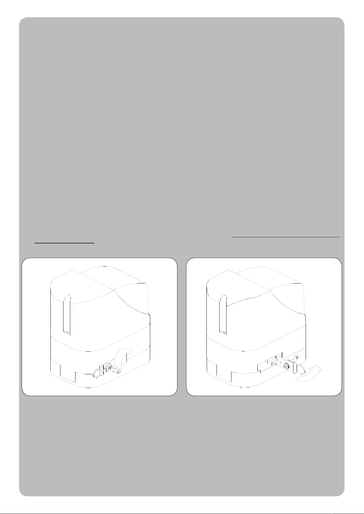
In assenza di tensione di linea levare il coperchietto della serratura,
infilare l’apposita chiave e ruotare come indicato in figura.
Quindi ruotare la leva di 90° per ottenere la gestione manuale del cancello.
La manovra manuale deve essere eseguita SOLO a porta ferma e DOPO aver tolto l’alimentazione alla centrale elettrica.
Nota: se il vostro impianto è dotato di un telecomando che dopo qualche tempo vi sembra funzionare peggio, oppure non funzionare
affato, potrebbe semplicemente dipendere dall’esaurimento della pila (a seconda del tipo, possono trascorrere diversi mesi fino a 2/3
anni). Ve ne potete accorgere dal fatto che la spia di conferma della trasmissione è debole, oppure si accende solo per un breve istante.
Prima di rivolgervi all’installatore provate a scambiare la pila con quella di un altro trasmettitore eventualmente funzionante: se questa
fosse la causa dell’anomalia, sarà sufficiente sostituire la pila con un’altra dello stesso tipo.
Nel caso voleste aggiungere nella vostra casa un nuovo tipo di automazione, rivolgendovi allo stesso installatore e alla Tau vi garantirete,
oltre che la consulenza di uno specialista e i prodotti più evoluti del mercato, il migliore funzionamento e la massima compatibilità delle
automazioni.
Vi ringraziamo per aver letto queste raccomandazioni, e vi auguriamo la massima soddisfazione dal vostro nuovo impianto: per ogni tipo
di esigenza rivolgetevi con fiducia al vostro installatore.
Italiano

2
In the event of a power failure, remove the cover of the lock, fit
the relative key and turn it as shown in figure.
Then, as shown in figure, lift the lever towards the outside to
move the gate manually.
The manual manoeuvre must ONLY be done with the door stopped and AFTER disconnecting power from the electrical control unit.
N.B.: if your remote control unit (if supplied) starts working badly after a time, or does not work at all, the batteries may be flat (they can last from
several months to 2/3 years depending on what type is used). This can be seen from the fact that the transmission confirmation LED gets dimmer
or only turns on for brief moments. Before contacting your fitter, try exchanging the battery with one from a good transmitter: if this is the reason
for the fault, simply replace the battery with another one of the same type.
If you wish to add a new automated system to your house, contact your fitter and we at Tau to have the advice of a specialist, the most developed
products on the market, best operation and maximum automation compatibility.
Thank you for reading these suggestions and we trust you are fully satisfied with your new system: please contact your fitter for any further
requirements.
English
INSTRUCTIONS AND WARNINGS FOR AUTOMATIC SYSTEM USERS
CONGRATULATIONS on choosing a Tau product for your automation system!
Tau S.r.l. produces components for automatic gates, doors, barriers and shutters. These include gear motors, control units, radio control devices, flashing
lights, photocells and accessories.
Tau products are exclusively made with top quality materials and processes and, as a company, we constantly research and develop innovative solutions
in order to make our equipment increasingly easier to use. We also pay great attention to all details (technology, appearance and ergonomics). The
extensive Tau range makes it possible for your fitter to choose the product which best meets your requirements.
Tau, however, does not produce your automated system as this is the outcome of a process of analysis, evaluation, choice of materials and installation
performed by your fitter.
Each automated system is unique, therefore, and only your fitter has the experience and professionalism required to create a system that is tailor-made
to your requirements, featuring long-term safety and reliability, and, above all, professionally installed and compliant with current regulations.
An automated system is handy to have as well as being a valid security system. Just a few, simple operations are required to ensure it lasts for years.
Even if your automated system satisfies regulatory safety standards, this does not eliminate “residue risks”, that is, the possibility of dangerous situations
being generated, usually due to irresponsible and/or incorrect use. For this reason we would like to give you some suggestions on how to avoid these
risks:
- Before using the system for the first time: ask your fitter to explain how residue risks can arise and read the instructions and warnings in the user
handbook that your fitter will have given you. Keep this manual for future use and, if you should ever sell your automated system, hand it over to the
new owner.
- Your automated system carries out your commands to the letter: irresponsible and/or incorrect use may cause it to become dangerous. Do not
use the system if people, animals and/or objects enter its operating area.
- IT IS NOT A TOY! Make sure children do not play near the system and keep the remote control device out of their reach.
- Faults: If you notice any abnormal behaviour, disconnect the system from the power supply immediately and perform the manual release operation
(see figure). Do not attempt to repair the door but call in your fitter: the system will operate manually as it did before installation.
- Maintenance: to ensure long life and totally safe operation, the system required routine maintenance, just like any other piece of machinery.
Establish maintenance times together with your fitter. Tau recommends a frequency of 6 months for normal domestic installations but this may vary
depending on the intensity of use (always every 3000 work cycles).
N.B.: All controls, maintenance work and/or repairs may only be carried out by qualified personnel.
- Do not modify the plant or the relative programming and adjustment parameters: your fitter will see to that.
N.B. Final testing, routine maintenance and any repairs must be documented by the fitter (in the relative spaces) and such documents kept
by the owner of the system (IF THE DOCUMENTS ARE NOT PRODUCED, THE WARRANTY WILL EXPIRE).
- Disposal: At the end of system life, make sure that it is demolished by qualified personnel and that the materials are recycled or disposed of
according to local regulations.
3
Ohne Spannungsversorgung den Deckel des Schlosses heben,
den Schlüssel einstecken und wie in Abbildung gezeigt drehen.
Dann den Hebel wie auf Abbildung gezeigt nach außen ziehen,
um das Tor von Hand zu bewegen.
Die manuelle Bewegung darf AUSSCHLIESSLICH bei stehendem Tor und NACH Abschalten der Versorgung zur Steuerung ausgeführt
werden.
Anmerkung: wenn eine Fernbedienung zu Ihrer Anlage gehört, die nach einer bestimmten Zeit schlechter oder gar nicht funktioniert, sollten Sie die
Batterie kontrollieren, die ganz einfach leer sein könnte (je nach Typ, kann die Batterie mehrere Monate bis 2-3 Jahre dauern). Sie können das am
Leuchtmelder bemerken, der die Übertragung bestätigt und nur schwach oder ganz kurz aufleuchten wird. Tauschen Sie die Batterie mit der eines
anderen, funktionierenden Senders aus, bevor Sie sich an den Installateur wenden: falls die Ursache der Betriebsstörung eine leere Batterie sein sollte,
genügt es, diese mit einer anderen gleichen Typs zu ersetzen.
Falls Sie Ihrem Haus eine weitere neue Automatisierung hinzufügen wollen, werden Sie sich bei Ihrem Installateur und bei Tau neben der Beratung
eines Fachmanns die fortgeschrittensten Produkte garantieren, die es auf dem Markt gibt, mit bestem Betrieb und maximaler Kompatibiltät der
Automatisierungen.
Wir danken Ihnen, dass Sie diese Hinweise gelesen haben und wünschen Ihnen volle Zufriedenheit mit Ihrer neuen Anlage. Wenden Sie sich für jeden
Bedarf vertrauensvoll an Ihren Installateur.
Deutsch
ANWEISUNGEN UND HINWEISE FÜR DEN BENUTZER DER AUTOMATISIERUNG
WIR GRATULIEREN IHNEN zur Wahl eines Tau Produktes für Ihre Automatisierung!
Tau S.r.l. stellt Komponenten für die Automatisierung von Toren, Türen, Schranken und Fenstern her: Getriebemotoren, Steuerzentralen,
Funksteuerungen, Blinkleuchten, Fotozellen und Zubehör.
Die Tau Produkte werden nur mit Materialien und Bearbeitungen hoher Qualität hergestellt, und unsere Firma ist auf der ständigen Suche nach
innovativen Lösungen, mit denen die Benutzung unserer Apparaturen, die in jeder Hinsicht (Technik, Aussehen und Ergonomie) besonders gepflegt
sind, immer einfacher wird: unter dem großen Tau Sortiment kann Ihr Installateur das Produkt auswählen, das Ihrem Bedarf am besten entspricht.
Tau ist aber nicht der Hersteller Ihrer Automatisierung, die dagegen das Ergebnis des Werks Ihres Vertrauensinstallateurs ist, der sich mit den
notwendigen Untersuchungen und Bewertungen, der Wahl der Materialien und der Verwirklichung die Anlage beschäftigen wird.
Jede Automatisierung ist daher einzigartig und nur Ihr Installateur kann eine Anlage ausführen, die Ihrem Bedarf entspricht (er besitzt die notwendige
Erfahrung und Professionalität), die sicher und auf Zeit zuverlässig und vor allem fachgerecht ist und mit den gültigen Vorschriften übereinstimmt.
Eine Automatisierungsanlage ist etwas wirklich bequemes, aber auch ein gutes Sicherheitssystem, und mit ein paar einfachen Maßnahmen wird sie
jahrelang dauern.
Auch wenn Ihre Automatisierung dem Sicherheitsniveau entspricht, das von den Vorschriften gefordert wird, schließt dies das Vorhandensein eines
„Restrisikos” nicht aus, bzw. der Möglichkeit, dass Gefahren aufgrund eines fahrlässigen und/oder falschen Gebrauchs erzeugt werden können. Aus
diesem Grund geben wir hier einige Verhaltensweisen an, um diese möglichen Restrisiken zu vermeiden:
- Bei der ersten Benutzung: bitten Sie Ihren Installateur, Ihnen den Ursprung der Restrisiken zu erklären, und lesen Sie die vorliegenden
Anweisungen und Hinweise für den Benutzer, die Ihnen vom Installateur übergeben werden. Bewahren Sie die Anleitung für zukünftige Probleme
auf, und übergeben Sie diese ggf. dem neuen Besitzer der Anlage.
- Die Automatisierungsanlage folgt getreu Ihren Befehlen: ein fahrlässiger und/oder unsachgemäßer Gebrauch kann gefährlich sein. Betätigen
Sie daher die Automatisierung nicht, wenn sich Personen, Tiere und/oder Gegenstände in ihrem Aktionskreis befinden.
- SIE IST KEIN SPIEL! Lassen Sie Kinder nicht in der Nähe der Anlage spielen und halten Sie die Fernbedienungen außer deren Reichweite.
- Störungen: schalten Sie bei jedem ungewöhnlichen Verhalten der Anlage die Stromversorgung zur Automatisierung ab und entriegeln Sie von
Hand (siehe Abbildung). Vermeiden Sie jeden persönlichen Eingriff und rufen Sie Ihren Installateur: nach dem Entriegeln wird die Anlage von Hand
funktionieren, wie vor der Installation.
- Wartung: um zu dauern und ganz sicher zu funktionieren, bedarf die Anlage wie jede andere Maschine einer periodischen Wartung. Legen Sie
die Wartungszeiten zusammen mit Ihrem Installateur fest. Tau empfiehlt für den normalen Hausgebrauch eine Wartung alle 6 Monate, was je nach
Gebrauchshäufigkeit unterschiedlich sein kann (immer ungefähr 3000 Arbeitszyklen).
N.B.: Eingriffe (Kontrolle, Wartung und/oder Reparatur) dürfen nur von Fachpersonal ausgeführt werden.
- Anlage und programmierte und eingestellte Parameter nicht ändern, das ist Aufgabe des Installateurs.
N.B.: Endprüfung, periodische Wartungsarbeiten und eventuelle Reparaturen müssen von dem, der sie ausführt, belegt sein (in den dazu
bestimmten Feldern); diese Unterlagen muss der Besitzer der Anlage aufbewahren (DIE GARANTIE WIRD UNGÜLTIG, FALLS DIE
DOKUMENTATION FEHLT).
- Entsorgung: stellen Sie am Ende der Lebensdauer der Anlage sicher, dass die Entsorgung durch Fachpersonal erfolgt und dass die Materialien
nach den örtlich gültigen Vorschriften recycled oder entsorgt werden.
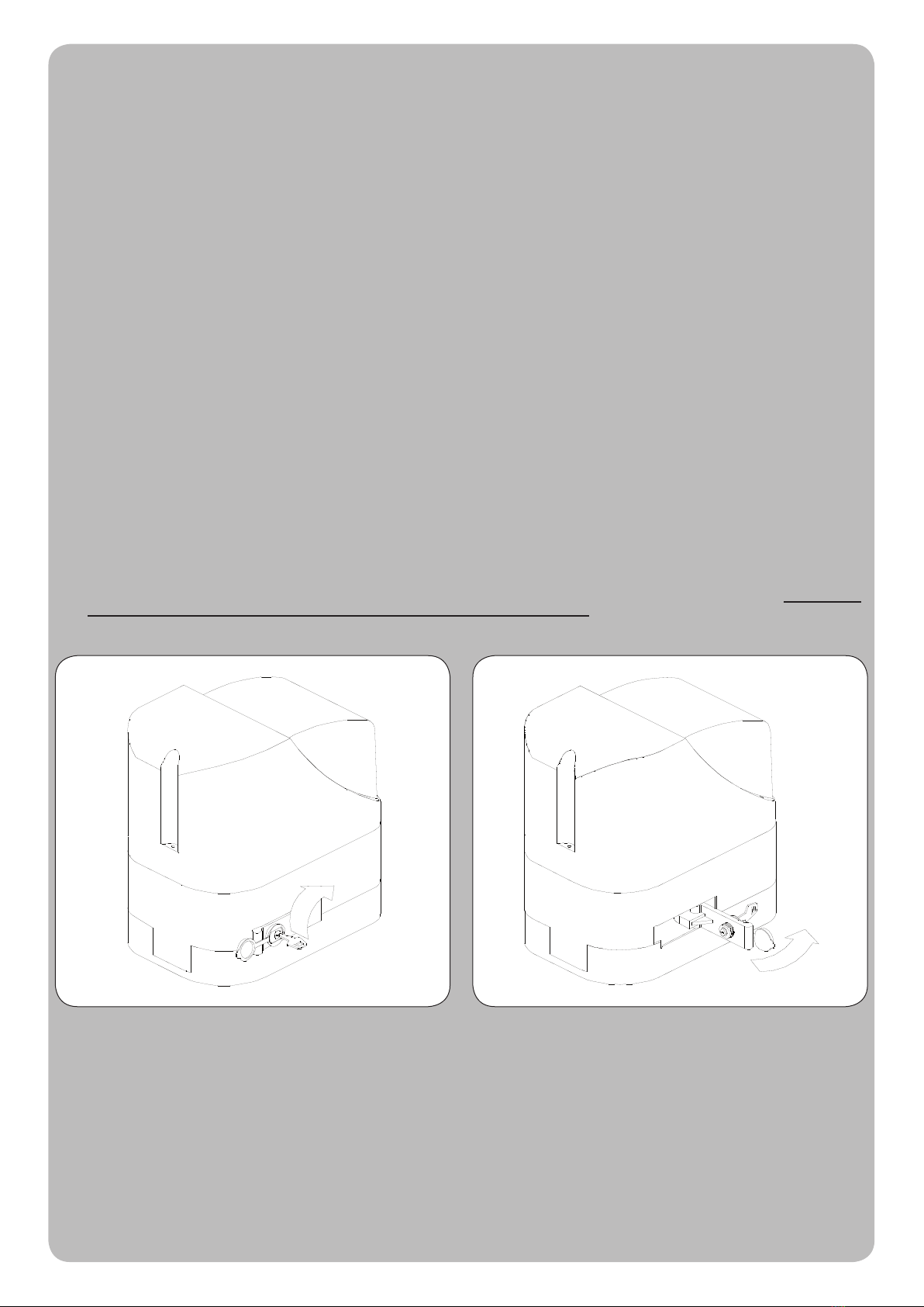
4
En cas de manque de courant, soulever le couvercle de la serrure,
enfiler la clé spéciale et la tourner comme l’indique la figure.
Puis, comme dans la figure, tirer le levier vers l’extérieur pour
pouvoir manœuvrer manuellement le portail.
La manœuvre manuelle doit être exécutée UNIQUEMENT avec la porte fermée et APRÈS avoir coupé l’alimentation de l’armoire électrique.
Note : si votre installation est munie d’une télécommande qui au bout de quelques temps semble moins bien fonctionner ou ne plus fonctionner du tout,
cela peut dépendre tout simplement de la pile (suivant le type sa durée est de plusieurs mois jusqu’à 2/3 ans). Vous pouvez vous en rendre compte à
travers le fait que le voyant de confirmation de la transmission est faible ou bien, s’il ne s’allume qu’un bref instant. Avant de vous adresser à l’installateur,
essayez d’échanger la pile avec celle d’un autre émetteur qui fonctionne correctement : si la cause de l’anomalie est celle-ci, il suffira de remplacer la
pile par une autre du même type.
Si vous désirez ajouter un nouveau type d’automatisme dans votre habitation, adressez-vous au même installateur et à Tau ; en plus du conseil d’un
spécialiste, vous aurez ainsi la garantie des produits les plus évolués sur le marché, du meilleur fonctionnement et du maximum de compatibilité entre
les automatismes.
Nous vous remercions d’avoir lu ces recommandations et nous espérons que votre nouvelle installation vous donnera toute satisfaction : pour tout type
d’exigence, adressez-vous en toute confiance à votre installateur.
Français
INSTRUCTIONS ET RECOMMANDATIONS DESTINÉES À L’UTILISATEUR DE L’AUTOMATISATION
FÉLICITATIONS pour avoir choisi pour votre automatisation un produit Tau !
Tau S.r.l. produit des composants pour l’automatisation de portails, portes, barrières, volets : opérateurs, logiques de commande, radiocommandes,
clignotants, photocellules et accessoires.
Les produits Tau sont réalisés exclusivement avec des matériaux et des usinages de qualité et en tant qu’entreprise, nous sommes à la recherche
constante de solutions innovantes qui simplifient de plus en plus l’utilisation de nos appareils, soignés sur tous les plans (technique, esthétique et
ergonomique) : dans la vaste gamme Tau, votre installateur peut choisir le produit qui satisfera au mieux vos exigences.
Tau toutefois ne produit pas votre automatisation qui est, en fait, le résultat d’un travail d’analyse, d’évaluation, de choix des matériaux et de réalisation
de l’installation effectué par votre installateur de confiance.
Chaque automatisation, par conséquent, est unique et seul votre installateur peut réaliser une installation suivant vos exigences (dans la mesure où
il est doté de l’expérience et de la qualification professionnelle nécessaire), sûre et fiable dans le temps et, surtout, effectuée dans les règles de l’art,
c’est-à-dire conforme aux normes en vigueur.
Une installation d’automatisation est d’une grande commodité, en plus de représenter un système de sécurité et, avec un minimum d’attentions, elle est
destinée à durer des années.
Même si l’automatisme en votre possession satisfait le niveau de sécurité requis par les normes, cela n’exclut pas l’existence d’un “risque résiduel”,
c’est-à-dire la possibilité que des situations de danger puissent se vérifier, à cause d’une utilisation non raisonnable et/ou erronée. Pour cette raison,
nous donnons quelques conseils sur les comportements à suivre pour éviter tout inconvénient :
- À la première utilisation : demandez à votre installateur de vous expliquer l’origine des risques résiduels et lisez ce manuel d’instructions et
de recommandations pour l’utilisateur qui vous a été remis par l’installateur. Conservez le manuel pour tout problème futur et n’oubliez pas de le
remettre à l’éventuel nouveau propriétaire de l’installation.
- L’installation d’automatisation exécute fidèlement vos commandes : une utilisation non raisonnable et/ou impropre peut devenir dangereuse.
Évitez par conséquent d’actionner l’automatisme quand des personnes, des animaux ou des objets se trouvent dans son rayon d’action.
- CE N’EST PAS UN JEU ! Faites en sorte que les enfants ne jouent pas à proximité de l’installation et conservez les télécommandes hors de leur
portée.
- Anomalies: à tout comportement anormal de l’installation, coupez l’alimentation électrique de l’automatisme et effectuez le déblocage manuel
(comme sur la figure). Évitez toute intervention personnelle et contactez votre installateur : une fois débloquée, l’installation fonctionnera
manuellement, comme avant l’automatisation.
- Maintenance : pour durer dans le temps et fonctionner en toute sécurité, comme toute autre machine, l’installation a besoin d’une maintenance
périodique. Établissez avec votre installateur un plan de maintenance. Tau conseille une intervention tous les 6 mois pour un usage domestique
normal qui peut varier suivant l’intensité d’utilisation (toujours tous les 3000 cycles de travail).
N.B. N’importe quel type d’intervention (contrôle, maintenance et/ou réparation) doit être effectué uniquement par du personnel qualifié.
- Ne pas modifier l’installation ni les paramètres de programmation et de réglage : la responsabilité en incombe à l’installateur.
N.B. l’essai de fonctionnement final, les maintenances périodiques et les éventuelles réparations doivent être documentées (dans les
espaces prévus à cet effet) par qui les exécute et les documents doivent être conservés par le propriétaire de l’installation (EN CASE DE
NON-PRÉSENTATION DE LA DOCUMENTATION, LA GARANTIE N’EST PLUS VALABLE).
- Démantèlement : à la fin de la vie de l’installation, assurez-vous que le démantèlement soit effectué par du personnel qualifié et que les matériaux
soient recyclés ou mis au rebut suivant les normes en vigueur au niveau local.

15
Serie SPEED
- - -- - - - - - - - - - - - - - - - - - - - - - - - - - - - - - - - - - - - - - - - - - - - - - - - - - - - - - - - - - - - - - - - - - - - - - - - - - - - - - - - - - - - - - - - - - - - - -

16
Serie SPEED
SCAVO
EXCAVATION
GRABEN
CREUSEMENT
EXCAVACIÓN
CANCELLO
GATE
TORE
PORTAIL
VERIA
225 mm
45 mm
318 mm
55 mm
CAVI
WIRES
KABELS
CABLES
CABLES
GUAINA
SHEAT
HULLE
GAINE
FUNDA
CANCELLO
GATE
TORE
PORTAIL
VERIA
TASSELLO
EXPANSION BOLT
SPREIZDUBELN
VIS TAPONÉE
TORNILLO TALADRADORE
157 mm
Table of contents
Other tau Gate Opener manuals


